Table of Contents
Advertisement
Quick Links
Advertisement
Table of Contents

Related Manuals for HP 480-0005-00-15


Summary of Contents for HP 480-0005-00-15
- Page 1 ® Tenor Carrier MultiPath Switch (CMS) Tenor and Quintum are registered trademarks. Tenor Carrier MultiPath Switch (CMS), PacketSaver, Quintum Technologies, Inc., VoIP Made Easy, TASQ, SelectNet, and SelectNet Technology are trade- marks of Quintum Technologies, Inc.
-
Page 2: Table Of Contents
Configuration ............1-12 P/N 480-0005-00-15... - Page 3 With DC Power ............2-39 P/N 480-0005-00-15...
- Page 4 CLI Menu Tree............4-4 P/N 480-0005-00-15...
- Page 5 View Alarm Status via Tenor CMS icon ........5-8 Launching Command Line Interface (CLI) from HP Openview ....5-8...
- Page 6 Replace System Fan (for CMS, 14 slot only) ....... . 8-11 Clean/Replace Foam Air Filter (for CMS, 14 slot only) ......8-11 P/N 480-0005-00-15 TOC-5...
- Page 7 If you need Additional Help ..........8-20 Appendix A: Getting Acquainted with Tenor CMS in the VoIP Network Appendix B: Specifications/Approvals GLOSSARY INDEX WARRANTY P/N 480-0005-00-15 TOC-6...
-
Page 8: About This Guide
Guide P/N 480-0005-00-15... -
Page 9: What's Included
• Appendix A: Getting Acquainted with Tenor CMS in the VoIP Network. A general overview of VoIP and how it relates to the Tenor CMS switch. • Appendix B: Specifications/Approvals: A list of Tenor CMS’s specifications and approvals. -
Page 10: Typographical Conventions
(i.e., Do not stack more than 4 units together.) A CAUTION provides information about how to avoid injury to yourself or to others (e.g., Do not install the equipment during a lightning storm). P/N 480-0005-00-15 About this Guide Preface-3... -
Page 11: Finding Help
VoIP terms and concepts. Extensive configuration help is available via the Command Line Interface help system. Just type help or ? from any prompt to obtain help. See Chapter 4: Getting Started with Command Line Interface (CLI) for more information. P/N 480-0005-00-15... -
Page 12: Chapter 1: Overview
1: Overview This chapter gives you a general overview of the Tenor® Carrier MultiPath Switch (CMS), including feature descriptions and capabilities. You will also find information about the organization of this product guide. Specifically, the following topics are covered:... -
Page 13: What Is Tenor Cms
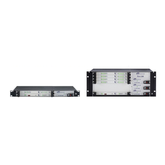
The Tenor Carrier MultiPath Switch (CMS) is a high-density VoIP (Voice over Internet Protocol) H.323 switch that digitizes voice and fax data and transmits it over the IP network. Tenor CMS is available in three configurations: CMS (14 slot), CMS960 (8 slot), and CMS240 (2 slot); each is a slotted, scalable system that intelligently switches calls over both the IP network and the PSTN in order to ensure high quality voice. -
Page 14: Features
T1, E1, and DSP functionality in the same card. Through the System Controller/CPU card, you can connect a PC’s console port as well as an Ethernet hub, switch, or router. In addition, the System Control- ler/CPU card provides one 10/100BaseT Ethernet port. -
Page 15: Dynamic Call Routing
If the network conditions for an IP call become unacceptable—according to the delay and packet loss specifi- cations you configure—Tenor CMS will switch the call to the PSTN automatically and transparently. The Tenor CMS continuously monitors your data network for jitter, latency and packet loss, and transparently switches customer calls to the PSTN when required. -
Page 16: Packetsaver
Tenor CMS unit, or another H.323 endpoint. The gatekeeper’s function- ality complies with the H.323 industry specifications for voice control and management. See H.323 Gate- keeper Services, later in this chapter, for more information. P/N 480-0005-00-15... -
Page 17: Powerful System Monitoring
Through the Command Line Interface (CLI) management system, you can view a list of active system alarms, as well as view an alarm history. Each alarm indicates the chassis’s operational status. Tenor CMS is also SNMP-capable with HP® Openview™ support. P/N 480-0005-00-15... -
Page 18: Capabilities
PSTN. The routing decision made by the Tenor CMS is based upon your configuration and the dialed number. Figure 1-2 Line Circuit Call Routing Line Circuits Circuit Call P/N 480-0005-00-15 Trunk Circuits Trunk Alarm St at us Alarm... -
Page 19: Intra-Trunk Routing - "Hairpinning
Ethernet Hot Swap Hot Swap Fault Fault Ground Reset +3.3V + 5V +12V -12V Strap Tenor CMS Ethernet (IP Network) PSTN A Circuit Call PSTN B VOIP Call Ethernet PSTN A Circuit Call PSTN B VOIP Call Ethernet P/N 480-0005-00-15... -
Page 20: Other Call Routing Options
PBX-configured direct connection between two PBXs in separate locations. The tie trunk bypasses the PSTN network. Your PBX does not need any additional configuration. Tenor CMS treats all the trunks the same without com- promising voice quality. P/N 480-0005-00-15 Trunk Circuits Trunk... -
Page 21: Hop-Off Pbx Call
The Tenor CMS unit acts as an SNMP agent—using HP Openview—to receive commands and issue responses to the network manager. The network manager will then be able to perform certain functions, such as receiving traps from Tenor CMS. -
Page 22: H.323 Gatekeeper Services
Through the border element, gatekeepers from multiple zones will be able to communicate. A border element also establishes relationships with other border elements to route between administrative domains. If a gatekeeper cannot resolve an address, it contacts the border element. P/N 480-0005-00-15 Chapter 1: Overview 1-11... -
Page 23: Call Services
• Primary Border Element IP Address. The IP address for the administrative domain’s Border Element (the Border Element is internal to the Tenor CMS unit; it is used to establish relationships with other P/N 480-0005-00-15 Gatekeeper Border Element Border Element... - Page 24 Discovery IP Address. The IP address a Tenor CMS uses to communicate with a Gatekeeper for service. • Discovery Port. The H.323 standard port a Tenor CMS uses to discover a Gatekeeper. • Registration Port. The H.323 standard port a Tenor CMS uses to register itself with a Gatekeeper. P/N 480-0005-00-15 Chapter 1: Overview 1-13...
-
Page 25: Chapter 2: Hardware Components
2: Hardware Components This chapter tells you what is contained in your hardware package. A description of each component is also included. Specifically, the following topics are covered: P/N 480-0005-00-15 Chassis Power Supplies WAN Cards Cables... -
Page 26: Hardware Description
Table 2-1 Board supported according to CMS Release Release Board Type P1.3.x T1 Card E1 Card DS1 Card (with DSP module) DSP Card System Controller Card CPU Card Release Release P1.4.x and P1.5.x higher Release Release P2.4.x P2.5.x P/N 480-0005-00-15... -
Page 27: Chassis - Cms (14 Slot)
• Reset Button. Enables you to reset the system. This function will be supported in a future release. • Ground Strap Socket. A ground connection is provided for ESD protection. P/N 480-0005-00-15 Chapter 2: Hardware Components Alarm Status Alarm... -
Page 28: Rear (With Ac Power)
When these are lit, they indicate the respective voltages are being output from the power supplies. When unlit, the voltage is not being supplied. See Chapter 8: Diagnostics/Maintenance for more information. • On/Off Power: A switch to turn power on and off. Rear (with AC power) NOTE: For pictorial purposes, Figure 2-2 is shown with 2 DS1 cards and the CPU Card. -
Page 29: Front (With Dc Power)
Chassis LEDs. The LEDs are indicators as to the status of the four voltage supplies. When these are lit, they indicate the respective voltages are being output from the power supplies. When unlit, the voltage is not being supplied. See Chapter 8: Diagnostics/Maintenance for more information. P/N 480-0005-00-15 Chapter 2: Hardware Components Alarm... -
Page 30: Rear (With Dc Power)
ESD Socket. A ground connection is provided for ESD protection. 10/100 Ethernet Link TX/RX Link TX/RX -48 |RTN| -48 |RTN| -48 |RTN| -48 |RTN| Power Plug Circuit Breaker Air Exhaust Earth Ground Terminal ESD Socket Power Receptacle Power Plug P/N 480-0005-00-15... -
Page 31: Chassis - Cms960 (8 Slot)
• Wrist Strap Ground Socket. Socket available in which to connect an ESD wrist strap for ESD protec- tion. P/N 480-0005-00-15 Chapter 2: Hardware Components QUINTUM TEC H N O LOG IES, IN C . -
Page 32: Rear (With Ac Power)
Power Inlet. Inlet for which you insert the supplied AC power cord. The unit requires 110-240 VAC. • On/Off Power: A switch to turn power on and off. • Strain Relief Mount. The Strain Relief Mount enables you to connect the power cord strain relief to the unit. -
Page 33: Front (With Dc Power)
• Wrist Strap Ground Socket. Socket available in which to connect an ESD wrist strap for ESD protec- tion. P/N 480-0005-00-15 Chapter 2: Hardware Components QUINTUM TEC H N O LOG IES, IN C . -
Page 34: Rear (With Dc Power)
OFF, the contacts will open. To ensure all power is disconnected from unit, open both circuit breakers. • Wrist Strap Ground Socket. Socket available in which to connect an ESD wrist strap for ESD protec- tion. 2-10 -48 RTN -48 RTN Supplementary Earth Ground Card Slots Wrist Strap Ground Socket P/N 480-0005-00-15... -
Page 35: Chassis- Cms240 (2 Slot)
Power Supply. One AC Power Supply. • Wrist Strap Ground Socket. Socket available in which to connect an ESD wrist strap for ESD protec- tion. P/N 480-0005-00-15 Chapter 2: Hardware Components QUINTUM TEC H N OLOGIES, IN C . Power A.C. -
Page 36: Rear View (With Ac Power)
Power Inlet. Inlet for which you insert the supplied AC power cord. The unit requires 110-240 VAC. • On/Off Power Switch. A switch to turn power on and off. • Fuse. Replaceable fuse. See Chapter 8: Diagnostics/Maintenance for more information. -
Page 37: Front View (With Dc Power)
Power Supply. One DC Power Supply. • Wrist Strap Ground Socket. Socket available in which to connect an ESD wrist strap for ESD protec- tion. P/N 480-0005-00-15 Chapter 2: Hardware Components QUINTUM TEC H N OLOGIES, IN C . Power Alarm D.C. -
Page 38: Rear View (With Dc Power)
The quantity will vary depending upon the number of cards you have inserted. • Wrist Strap Ground Socket. Socket available in which to connect an ESD wrist strap for ESD protec- tion. 2-14 Wrist Strap Ground Socket Card Slots P/N 480-0005-00-15... -
Page 39: System Controller Card (Available For Cms P1.5.X )
Figure 2-13 System Controller Card 10/100 Base-T Ethernet port. This port provides one RJ-45 jack for connection to a 10/100 BASE-T Ether- net LAN switch or hub via RJ-45 cable. The input/output signals are listed in Table 2-2. P/N 480-0005-00-15... - Page 40 TX - RX + RSVD RSVD RX - RSVD RSVD 2-16 Signal Definition Transmit Data Transmit Data Receive Data Reserved Reserved Receive Data Reserved Reserved Color White w/orange Orange White w/green Blue White w/blue Green White w/Brown Brown P/N 480-0005-00-15...
- Page 41 RSVD RST. Resets the System Controller board along with the entire chassis. ABT. Abort recessed push button switch used for internal Quintum use only. LEDs. LEDs provide a high level indication of the system controller card activity. Basic definitions follow.
-
Page 42: Cpu Card (Available For Cms P2.X.x)
Through the CPU card, you are able to perform system functions, such as resetting the system, connect to an Ethernet hub/switch, or connect to a PC. In addition, LEDs provide a high level indication of system and chas- sis activity. -
Page 43: Front View
Each Link LED relates to one Ethernet line on the rear of the cards. P/N 480-0005-00-15 Figure 2-16 CPU Card (Front) Card Activity LEDs... -
Page 44: Rear View
10/100 Base-T Ethernet port. The Ethernet port (one port is functional; the other three ports are not used) provides an RJ-45 jack for an individual connection to a 10/100 Ethernet LAN switch or hub via RJ-45 cable. The Ethernet port is individually configured with a unique IP and MAC address. - Page 45 Figure 2-19 DB-9 Female Connector Pin Order Table 2-5 Serial RS232 DB-9 Connector Pinouts Pin # RSVD RSVD RSVD RSVD RSVD RSVD Config switch. For internal Quintum use only. P/N 480-0005-00-15 Signal Definition Transmit Data Transmit Data Receive Data Reserved Reserved Receive Data Reserved...
-
Page 46: Wan Cards
A crossover cable is required when connecting to a Line side (PBX) interface (when supplied by Quintum, this is a red RJ-45 cable). A straight cable is required when connecting to the trunk side (PSTN) interface (when supplied by Quintum, this is a green RJ-45 cable). P/N 480-0005-00-15 Chapter 2: Hardware Components 2-22... - Page 47 For both DSP banks, red indicates power-up or DSP module is usable; green indicates at least one DSP chan- nel is in use. Unlit indicates the DSP is not in use. Ethernet LEDs. Not available in current release. P/N 480-0005-00-15 Figure 2-20 DS1 Card Ethernet LEDs...
- Page 48 (i.e., PBX or PSTN). The input/output signals are listed in Table 2-6. Table 2-6 DS1 Signal for DS1Card - RJ-48 Ports Port# Ethernet port LEDs (rear view). Not available in current release. P/N 480-0005-00-15 Figure 2-21 RJ-48 Port Pin Order Signal RR -...
-
Page 49: T1 Wan Card
LED relates to one line on the rear of the T1 WAN card. For example, Span Status 1 indicates the operational activity of port 1 on the rear of the T1 WAN card. If all LEDs are lit green, the lines are operating properly. P/N 480-0005-00-15 Chapter 2: Hardware Components... - Page 50 T1 and a piece of network equipment (i.e., PBX or PSTN). The input/output signals are listed in Table 2-7. Table 2-7 Input/Output Signals for WAN T1 Card RJ-48 Ports Port# P/N 480-0005-00-15 Figure 2-23 RJ-48 Port Pin Order Signal RR -...
-
Page 51: E1 Wan Card
LEDs. The E1 card contains eight Span Status LEDs, viewable from the front of the chassis, to provide a high level indication of the system operational mode and chassis activity, including alarm activity. Each LED P/N 480-0005-00-15 Figure 2-24 E1 WAN Card... - Page 52 E1 and a piece of network equipment (i.e., PBX or PSTN). The input/output signals are listed in Table 2-8. Table 2-8 Input/Output Signals for WAN E1 Card RJ-48 Ports Port# P/N 480-0005-00-15 Figure 2-25 RJ-48 Port Pin Order Signal RR -...
-
Page 53: Dsp Resource Card
Table 2-9 for the required number of DSP cards per various T1 or E1 requirements. WAN Card Usage 1 T1 Card (24 channel usage) 1 E1 Card (30 channel usage) P/N 480-0005-00-15 Chapter 2: Hardware Components Figure 2-26 DSP Card LEDs... - Page 54 DSP Bank 4: Lights for any DSP card activity on that bank. DSP Bank 4a: Lights when DSP card activity is more than 50%. Hot Swap. A lit blue light indicates that the DSP card is not in service. P/N 480-0005-00-15 Chapter 2: Hardware Components 2-30...
-
Page 55: Cables
The RJ-45 (ISO 8877) connector is the EIA/TIA standard for Unshielded Twisted Pair (UTP) cable; the wiring color codes are UTP Standard Coloring. The pin order is shown in Figure 2-27. P/N 480-0005-00-15 Table 2-10 Cables Supported All units T1/E1 connection to Line Side (PBX) inter- face. -
Page 56: Ethernet Cable (10/100))
Pin # Table 2-11 RJ-45 (10/100BT) Connector Pinouts Pin # TX + TX - RX + Unused Unused RX - Unused Unused P/N 480-0005-00-15 Connects to Signal Definition Transmit Data Transmit Data Receive Data Unused Unused Receive Data Unused Unused... -
Page 57: Rj-48 Cables
Table 2-12 RJ-48 Connector Pinouts for T1/E1/DS! Pin # RX ring RX tip RSVD TX ring TX tip RSVD RSVD RSVD P/N 480-0005-00-15 Figure 2-29 RJ-48 Pin Order Side View Top View Connects to Signal Definition Receive Ring Receive Tip Reserved... - Page 58 Reserved TX ring Transmit Ring TX tip Transmit Tip RSVD Reserved RSVD Reserved RSVD Reserved P/N 480-0005-00-15 Connects to Definition Color for Connector 1 White w/orange Orange Blue White w/blue Chapter 2: Hardware Components Connector 2 Pin # Color for Connector 2...
-
Page 59: To Db-9 Null Modem Cable (For System Controller Card)
Table 2-14 DB-9 Connector Pinouts Pin # Function RSVD RSVD RSVD RSVD RSVD P/N 480-0005-00-15 Chapter 2: Hardware Components 1 2 3 4 5 6 7 8 9 5 4 3 2 1 9 8 7 6 Connects to Pin #... -
Page 60: Serial Rs-232 Cable (For Cpu Card)
Table 2-15 DB-9 Connector Pinouts Pin # Function RSVD RSVD RSVD RSVD RSVD RSVD P/N 480-0005-00-15 Chapter 2: Hardware Components 1 2 3 4 5 6 7 8 9 5 4 3 2 1 9 8 7 6 Con nects to Pin # Description... -
Page 61: Power Supplies
There are two colors for the LED: red or green. Green indicates AC input; red indicates that input/output failed or there is a power fault. For more information, see Chapter 8: Diagnostics/Maintenance. P/N 480-0005-00-15 Chapter 2: Hardware Components Figure 2-38 Power Supplies... -
Page 62: Cms960 (8 Slot)
Power (LED) will be unlit. NOTE: For illustration purposes, the CMS960 (8 slot) with AC is shown. Figure 2-39 CMS960- AC Power Supplies P/N 480-0005-00-15 Chapter 2: Hardware Components QUINTUM TEC H N O LO GIES, IN C . QUINTUM TEC H N O LO GIES, IN C . -
Page 63: Cms240 (2 Slot)
Alarm (LED). Red LED indicates that input/output failed or there is a power fault. If this LED is lit, the Power (LED) will be unlit. NOTE: For illustration purposes, the CM240 (2 slot) with AC is shown. Figure 2-40 CMS240 - AC Power Supplies QUINTUM TEC H N OLOGIES, IN C . Power A.C. Power Supply P/N 480-0005-00-15 2-39... -
Page 64: Chapter 3: Installation
This chapter gives you installation instructions, as well as how to position the chassis successfully within your network. Specifically, the following topics are covered: P/N 480-0005-00-15 Pre-Installation guidelines Position the chassis Connect to Line Circuit, Trunk Circuit, LAN and PC... -
Page 65: Inspect Package Contents
If a listed component is not included in your package, contact your customer service representative. Install in Rack Locate the Tenor CMS chassis within the same area as your PBX, Ethernet hub, switch, router, and/or PSTN patch panel. The chassis is intended to be installed in a 19” rack. - Page 66 2. Align the chassis mounting brackets flush with the rack’s mounting holes (see Figure 3-1) and follow the vendor specific instructions for rack installation. The screws provided require a Phillips #2 screwdriver. 3. Ensure the chassis is secured firmly to the rack at four points. P/N 480-0005-00-15 Chapter 3: Installation...
- Page 67 Ethe rnet UINTUM UINTUM ECHNOLOGIES, INC. ECHNOLOGIES, INC. Reset UINTUM UINTUM TE CHNOLOGIE S, TECHNOLOGIES, INC. INC. Span Status Link TX/R X 10 /1 00 Etherne t Hot Swap Hot Swap Fault Fault Ground Strap Reset +3.3V +12V -12V P/N 480-0005-00-15...
-
Page 68: Connection
DSX-1), otherwise, configure the Digital Interface to DS-1 to enable the built-in CSU via Com- mand Line Interface (CLI). See Chapter 4: Getting Started with Command Line Interface (CLI). NOTE: Connecting to the patch panel may require trained telephone personnel. P/N 480-0005-00-15 RJ-48 Patch Panel Chapter 3: Installation... -
Page 69: Connect To Line Interface - Pbx
If you are connecting to an external CSU, ensure the Digital Interface is configured as short haul (or DSX-1), otherwise, configure the Digital Interface to DS-1 to enable the built in CSU via Com- mand Line Interface (CLI). See Chapter 4: Getting Started with Command Line Interface (CLI). RJ-48 Crossover P/N 480-0005-00-15... -
Page 70: Connect To Ethernet Lan (With System Controller Card)
1. Plug one end of the grey RJ-45 ethernet cable into the front of the System Controller card’s port labeled 10/100 Ethernet. 2. Plug the other end of the cable into your Ethernet hub/switch. If a custom cable or adapter is required, see Chapter 2: Hardware Components for the Ethernet RJ-45 10/100 pinout information. -
Page 71: Connect To Ethernet Lan (With Cpu Card)
1. Plug one end of the grey RJ-45 ethernet cable into one of the ports on the CPU rear transition module labeled 10/100 Ethernet. 2. Plug the other end of the cable into the Ethernet hub/switch port. If a custom cable or adapter is required, see Chapter 2: Hardware Components for Ethernet RJ-45 10/100. -
Page 72: Connect To Pc Console (With System Controller)
Console. (See Chapter 2: Hardware Components for RS-232 connector pinouts.) 2. Insert the female end of the DB-9 cable into your workstation’s serial port (see your PC documentation for more information about this port). P/N 480-0005-00-15 Figure 3-6 Connect to PC Com Tenor... -
Page 73: Connect To Pc Console (With Cpu)
Console. (See Chapter 2: Hardware Components for serial RS-232 connector pinouts.) 2. Insert the female end of the DB-9 cable into your workstation’s serial port (see your PC documentation for more information about this port). 3-10 Figure 3-7 Connect to PC Com DB-9 P/N 480-0005-00-15... -
Page 74: Connect Power - Cms (14 Slot), Dc Only)
See Figure 3-8. Each circuit breaker has a dual colored rocker. Pushing down on the left side of the breaker (ON/1) will close the switch and expose a red indicator that shows the user that the contacts are made (closed). - Page 75 Secure both screws in the face of the Plug, with a straight blade screwdriver of size 0.023" x 0.137", (0.6 x 3.5mm) Caution: Screws must be torqued between a minimum of 4.4 lbs.in,(0.5 Nm) and a maximum of 5.3 lbs. in (0.6 Nm) P/N 480-0005-00-15...
- Page 76 The chassis power connections are now complete. With the WAN cards and power supplies secured to the chassis, close the circuit breaker(s) on the Tenor CMS. Verify that the STATUS LEDs on the power supplies are green a few seconds after turn on. P/N 480-0005-00-15 Chapter 3: Installation 3-13...
-
Page 77: Connect Power - Cms960 (8 Slot) And Cms240 (2 Slot), Dc Only
For illustration purposes, the CMS240 (2 slot) is shown. Figure 3-13 DC Circuit Breaker and Power Inlet -48 RTN Chassis Rear 3-14 ) and insulation rated at a minimum of 90° C or better must be used for all Circuit Breaker -48 RTN Power Inlet P/N 480-0005-00-15... - Page 78 CMS. 7. Close the circuit breaker(s) on the Tenor CMS. Verify that the STATUS LEDs on the power supplies are green a few seconds after turn on. P/N 480-0005-00-15 Figure 3-14 Strip away wire DC Power Wire Strip Length 10 - 14 AWG 0.33 (8.5 mm)
-
Page 79: Install Power Cord Strain Relief (Ac Only)
2. Push the rivet into the Strain Relief Mount at the rear of the unit. See Figure 3-17. Figure 3-17 Insert clamp in Strain Relief Mount Strain Relief Mount P/N 480-0005-00-15 Loop long piece around cord. Power cord AC Power Plug... -
Page 80: Power Up The System (For Ac Unit)
3. You may also provide ground using the supplementary Earth Ground post (see Prevent Electrostatic Dis- charge Damage). 4. Locate the on/off switch on the front of the chassis (For Tenor CMS 14 slot) or the rear of the chassis (for CMS 240 and CMS960), click the switch to On. -
Page 81: Prevent Electrostatic Discharge Damage
The chassis provides an Earth Ground post to provide an additional connection to an approved safety earth ground. Connect earth ground to the post on the rear of the chassis called Supplemental Earth Ground. P/N 480-0005-00-15 Chapter 3: Installation 3-18... -
Page 82: Assign Ip Address
11. Click on Call>Call. A connection to the CMS chassis will be established. 12. Press the Tenor CMS power switch to On. After the bootup sequence, the login prompt will appear. 13. Enter a login name. The default login name is admin. - Page 83 18. For Default Gateway, choose whether there should be a default gateway (router) which routes packet data outside of your LAN, and enter its IP address. The CMS will automatically reboot with the new IP address. P/N 480-0005-00-15 Chapter 3: Installation 3-20...
-
Page 84: Install Software Upgrade Via Cms Software Update Utility
3. Click on Update (from Update from Disk). A message will appear, asking you to first backup the current files. 4. Click Yes to backup. (If you choose No, go to step 9.) The Tenor CMS Backup screen will be displayed. See Figure 3-20. P/N 480-0005-00-15 Figure 3-19 Main Upgrade Screen Chapter 3: Installation 3-21... - Page 85 14. Click Upgrade (to Cancel, click on Cancel). When completed, a message will alert you that the software and configuration settings have been updated. 15. Click on Release Notes to display the latest Release Notes; click on Continue to reset the unit. The unit will reset. P/N 480-0005-00-15 Figure 3-20 Main Backup Screen Chapter 3: Installation 3-22...
-
Page 86: Upgrade Via Network
5. Click on Login. The downloaded files will be copied to your hard disk under c:\Tenor_CMS\CMSCode_r1344. Backup 1. Click on Backup. 2. The Quintum Tenor CMS Backup Utility screen will be displayed. See Figure 3-22. P/N 480-0005-00-15 Chapter 3: Installation 3-23... -
Page 87: Restore Previous Versions
6. Enter the password. 7. Click Restore to continue. The restore procedure will begin. When completed, a message will display to tell you where the restored files have been located (i.e., c:\Tenor_CMS\Backup_09-15-2002). P/N 480-0005-00-15 Figure 3-22 Main Backup Screen Chapter 3: Installation... - Page 88 4: Getting Started with Command Line Interface (CLI) This chapter tells you to how use access the CLI and understand the CLI modes. Specifically, the following topics are included: P/N 480-0005-00-15 Access CLI Understand CLI modes View Menu Tree...
-
Page 89: Chapter 4: Getting Started With Command Line Interface (Cli)
Diagnostic. The Diagnostics mode provides a set of utilities to perform diagnostic and testing procedures. For example, through this mode you are able to ping other units. P/N 480-0005-00-15... -
Page 90: Chapter 4: Getting Started With Command Line Interface
User Login IDs There are two types of user logins: user and admin. The admin level enables you to view and change informa- tion. The user level enables you to view the information but not configure via CLI. P/N 480-0005-00-15... -
Page 91: Cli Menu Tree
See CLI Menu Tree - Expanded View for a complete list of all CLI options. CLI Menu Tree - Basic View SIte IPDialPlan PUBlicNumberingPlan DialPlan PRIVateNumberingPlan DigitalInterface Figure 4-1 Menu Tree - Basic View VoIP BorderElement MasterChassis Slots 1-14 DeVice EthernetInterface DoMain ZoNe RouteDirectory GateWay Number Directories AutoSwitchNumber BypassNumberDirectory HuntLDNDirectory-pub1 HuntLDNDirectory-prv1 HopoffNumberDirectory P/N 480-0005-00-15... -
Page 92: Cli Menu Tree - Expanded View
- CDRServerIPAddr - CDRPassWord - ChannelGroup (same for other Channel Groups) - SignalingGroupAttached - RoutingGroupAttached - SL 1 (same for slots 2 - 14)* - Type - SlotNumber - DeVice* - DigitalInterface* - PortNumber - LineType - LAW P/N 480-0005-00-15... - Page 93 - ServiceAddressIPAddr - ZOne* - GateWay* - NumberDirectories* - BypassNumberDirectory-1 - HuntLDNDirectory-pub1 - HuntLDNDirectory-prv1 - HopoffNumberDirectory-1 - AutoSwitchNumberDir-1 P/N 480-0005-00-15 Chapter 4: Getting Started with Command Line Interface VoIPNetwork - DoMain - ZoNe - GateWay - VoiceCodec - CodecVoiceCoding - CodecPayloadSize...
- Page 94 - PUBlicNumDigits - PRIVateNumDigits - TwoStageDialing - AccessNumber - AccessFormat - Enabled MultiPath - IVRType - IVRAccessNumber - IVRCardNumLength - IVRLanguage - IVRMultipleSession - IVRRequestPreferrdLanaguage - EnableExternalRouting - AutoSwitchNumberAttached - BypassNumberDirAttached [1..8] - PUBHuntLdnDirAttached [1] - PRIVHuntLdnDirAttached [1..4] P/N 480-0005-00-15...
- Page 95 - DiscToneFreq2 - DiscToneONTime - DiscToneOFFTime - GateKeeperParam* - DiscoveryAddressIPAddr - MulticastDiscoveryIPAddr - PrimaryBEIPAddr - SecondaryBEIPAddr - ZoneName - PassWord - EndPointAddressDirectory* - QOSPolicy* - AutoSwitchThreshold - RouteDirectory - StaticRoute-1 - name - CallSignalIP - Registered - IPRoutingGroupAttached P/N 480-0005-00-15...
-
Page 96: Access Cli
Once the cable is connected and the Tenor CMS is powered on, open a HyperTerminal session (or other termi- nal emulation program) as follows: 3. Click Start > Programs > Accessories > Communications > HyperTerminal. The HyperTerminal window will be displayed. P/N 480-0005-00-15 Chapter 4: Getting Started with Command Line Interface... - Page 97 IP address from the host portion of the IP address. 18. For Default Gateway prompt, enter the IP address for the default gateway (router) which routes a packet data outside of your LAN. CMS will reboot automatically. 4-10 P/N 480-0005-00-15...
-
Page 98: Move Around Within Cli
Diagnostic Maintain Monitor Move within modes To move to any other CLI menu item, type the desired menu item from the current prompt. P/N 480-0005-00-15 Chapter 4: Getting Started with Command Line Interface Enter config or co diagnostic or diag... -
Page 99: Execute Commands
-t. Displays all options in the system (the complete menu tree). show -v. Displays version number. show -p. Displays the CLI menu path for the current level. show -o <option>. Displays all options of the given type. 4-12 P/N 480-0005-00-15... -
Page 100: Clear
Displays help on a slot option. help set. Displays help on set command. help conf. Displays help on configuration mode. Logout Logs out of the current session. The Telnet session will be immediately terminated. P/N 480-0005-00-15 Chapter 4: Getting Started with Command Line Interface 4-13... -
Page 101: Configuration Mode
Before creating an association between any options, make sure both CLI options for the association exist; the association can be made from either end. Example: Set an attribute as follows: config-DialPlan-1# set internationalprefix[2] 3. Assigns 2nd element of InternationalPrefix (part of Dial Plan option) to 3. 4-14 P/N 480-0005-00-15... - Page 102 To detach a selected CLI option from another, type set followed only by the name of the option you want to detach. Example config-ChannelGroup-1# set SignalingGroupAttached (or set sga). Detaches ChannelGroup -1 to ISDN SignalingGroup-1. P/N 480-0005-00-15 Chapter 4: Getting Started with Command Line Interface 4-15...
- Page 103 Alias Address. To remove the attribute for a special menu option, you must first have that menu option selected. See below. Example: config-NumberDirectories-1# remove 1. Removes AutoSwitch index 1 in the selected NumberDirec- tories. config-HooffNumberDirectory-1# remove 2. Removes HopoffNumber index 2 from the selected HopOffNumberDir. 4-16 P/N 480-0005-00-15...
- Page 104 Configuration mode and all changes will be submitted. NOTE: Changes from other telnet sessions will also be submitted, if any. After you submit, the prompt will change from “*” (indicating changes) to # (indicating no changes). P/N 480-0005-00-15 Chapter 4: Getting Started with Command Line Interface 4-17...
- Page 105 To display the time, go to the time prompt in config mode. Example time Displays the time. To set the time, type time followed by the mm (month)/dd (day)/yy (year)/hh (hour):mm (minute):ss (second). Example time 05/11/01/15:45:00. Sets the time to May 11, 2001 at 3:45. 4-18 P/N 480-0005-00-15...
-
Page 106: Maintenance Mode
Type yes to reset or no to cancel the command. For more information on this command, see Chapter 8: Diagnostics/Maintenance. P/N 480-0005-00-15 Chapter 4: Getting Started with Command Line Interface... -
Page 107: Monitor Mode
Default level number is 1. Example From any prompt listed above, type status L1. Displays the status of the selected option according to the level you choose (L1, L2, or L3). For example, at the monitor-Slot-SL1 prompt, type status L1. 4-20 P/N 480-0005-00-15... -
Page 108: Diagnostic Mode
Changes the level value of CAS from the previous example from Level 3 to Level 2. evlog c. Clears all event logs. ev help. displays help for the modes. P/N 480-0005-00-15 Chapter 4: Getting Started with Command Line Interface 4-21... -
Page 109: Configure Common Cli Options
The Gatekeeper collects, manages, and distributes call routing information; it performs call routing functions, such as bandwidth control, call control signaling and call authorization for Gateways, IP phones, and H.323 terminals. Example config-CommonGKParam-1* set PrimaryBEIPAddr xxx.yyy.zzz.aaa config-CommonGKParam-1* set ZoneName ozone 4-22 P/N 480-0005-00-15... -
Page 110: Gateway
If no daughter boards are installed, only Device 1 is valid. Issuing a show command from the device level will show any settings at the device level and any digital interfaces that might be present on the board. P/N 480-0005-00-15 Chapter 4: Getting Started with Command Line Interface... -
Page 111: Switch Protocol
Law 1 (1 = aLaw) config-DigitalInterface-1# set LineCode 2 (2 = HDB3) Switch Protocol For an ISDN signaling group (PRI signaling group), you must configure the switch protocol. The example below shows you how to set the protocol to ETSI. Example... -
Page 112: Chapter 5: Working With Snmp
This chapter tells you how to use and manage Tenor CMS’s Simple Network Management Protocol (SNMP) feature, which is managed via Hewlett® Packard’s HP Openview Network Node Manager. Specifically, this chapter tells you how HP OpenView auto-discovers a Tenor CMS unit, as well as generate SNMP traps for existing alarm messages. -
Page 113: What Is Snmp
The Tenor CMS unit supports the SNMP protocol; specifically, Hewlett® Packard’s HP Openview software acts as the SNMP network manager for the Tenor CMS unit. Once you set up HP Openview to view and “auto-discover” Tenor CMS as a network device using SNMP, HP Openview will be able to issue commands, get responses, and perform certain functions. -
Page 114: Installation Requirements
Installation Requirements You will need to install and run HP Openview NMS 6.0 in order to recognize the Tenor CMS as an SNMP agent. Below are basic hardware and software requirements you will need to install HP Openview. See your HP Openview documentation for detailed information and installation instructions. -
Page 115: Installation
Chapter 5: Working with SNMP Installation There are two steps you need to accomplish before HP Openview can interact with a Tenor CMS unit as an SNMP agent. • Download and install HP Openview configuration files specific for Tenor CMS •... - Page 116 FORMAT Received trap:generic #$G specific #$S. $#args:$* SDESC Uswcomment EDESC EVENT Uswcomment .1.3.6.1.4.1.6618.2.0.0 "Status Events" Normal FORMAT Received trap:generic #$G specific #$S. $#args:$* SDESC Uswcomment P/N 480-0005-00-15 Chapter 5: Working with SNMP # QUINTUM Digital Tenor # QUINTUM Analog Tenor...
-
Page 117: Configure Network Manager Ip Address
Through Tenor CMS’s Command Line interface (CLI), you can configure the IP address for the network man- agement site where HP Openview is running. Once the IP address is configured, the Tenor CMS will be able to process and generate traps for existing alarms, which will enable HP Openview to monitor the Tenor CMS unit for alarm states. - Page 118 <ip> and the third type set snmptrapip3 <ip>. 10. Repeat step 9 for each network manager (up to 3). 11. Type submit. The new IP address(es) will be submitted to the applicable Tenor CMS unit. P/N 480-0005-00-15 Chapter 5: Working with SNMP...
-
Page 119: Working With Snmp
View Alarm Status via Tenor CMS icon Through the color of a Tenor CMS icon on the HP Openview desktop, you can determine the alarm state of the unit as well as view the corresponding alarms. Valid icon colors are listed below. -
Page 120: Set Up Tenor Cms Status Polling
IP address using the Tenor CMS’s Command Line Interface (CLI). We do not recom- mend polling more than 10 Tenor CMS units. 1. From the HP Openview desktop, right-click on the desired Tenor CMS unit icon and select Object Proper- ties. -
Page 121: Chapter 6: Call Detail Recording
This chapter tells you how to display and understand the Call Detail Recording (CDR) feature. Examples are included later. Specifically, the following topics are included: P/N 480-0005-00-15 Description of CDR Connect Tenor CMS unit to CDR Server Understand CDR data... -
Page 122: Overview
Any CDRs not collected from the Tenor CMS unit will be lost if the unit is powered down. The CDR software and Billing software mentioned is 3rd party software, and is not provided by Quintum. P/N 480-0005-00-15... -
Page 123: Establish Connection Between Tenor Cms And Cdr Server
(extended CMS format with session ID), 100 (standard format with session ID functionality), 101 (extended format with session ID functionality), 103 (extended CMS format with session ID functional- ity), 104 (extended CMS format with session ID functionality). P/N 480-0005-00-15 Chapter 6: Call Detail Recording CDR Server... -
Page 124: Configure Tenor Cms For Connection To Cdr Server
1. From the directory in which you are working, right click on the cdrserver.cfg file. At the Open with option, choose Notebook. 2. Scroll down to the line stating cdr_password. Next to that line, enter the desired password. Valid entry: up to 30 characters. P/N 480-0005-00-15... -
Page 125: Tenor Cms Establishes Connection With Cdr Server
CDR that it has received from the Tenor CMS unit. If the last CDR number is unknown, the server should send 0 for the sequence number. After this exchange, the Tenor CMS will start delivering new CDRs to the server. P/N 480-0005-00-15 Chapter 6: Call Detail Recording... -
Page 126: Cdr Output
1 again. If the system has a problem and loses connectivity, the CDR server can send the Tenor CMS unit the last Call ID that is received. The Tenor CMS unit will reply with all records that contain a Call ID which is greater than the one last received. P/N 480-0005-00-15... - Page 127 Resource Unavailable, Unspecified. This cause is used to report a resource unavailable event only when no other cause applies. Local IP Address: The IP address for the Tenor CMS unit originating the CDR. The entry will be in the fol- lowing format: xxx.xxx.xxx.xxx. P/N 480-0005-00-15 Chapter 6: Call Detail Recording...
- Page 128 Local Call ID #. Unique identification number, generated by the local-side Tenor CMS, for call record match- ing purposes. Generated for all IP calls. For a given IP call, the Local Call ID on one Tenor should match the Remote Call ID of the other. P/N 480-0005-00-15...
-
Page 129: Sample Record For Extended Cms Cdr Format 3, 4, 103, 104
Disconnect Cause Code: The Q.931 cause value assigned if the call is not connected. Possible common entries are listed below. This field will be blank if the call was connected. P/N 480-0005-00-15 Chapter 6: Call Detail Recording... - Page 130 Incoming Channel: If the call is incoming, this field identifies which channel the call came in on. Valid entry: 1-31. This field will be empty if the call is an incoming VoIP call. P/N 480-0005-00-15 Chapter 6: Call Detail Recording...
- Page 131 Incoming/Outgoing IP DN. If this is an incoming IP call, the number displayed will be the number as received from the other endpoint. If this number is an Outgoing IP call, the number displayed will be the DN as it was sent out over IP (Outgoing number plus prepended digits). P/N 480-0005-00-15 6-11...
-
Page 132: Chapter 7: System Alarms
7: System Alarms This chapter tells you how to use the Alarm Manager to view and understand alarms generated by the system. Specifically, the following topics are included: P/N 480-0005-00-15 Description of Alarm Manager Delete and filter alarms Monitor alarm history... -
Page 133: Monitor Alarms
2 = Major (major problem is detected). 3 = Minor (minor problem is detected). 4 = Info (Information about a minor problem). Varies. Slot 1 through 14 (CMS) Slot 1 through 8 (CMS960) Slot 1 or 2 (CMS240) P/N 480-0005-00-15... - Page 134 Field Device # Line # Channel # Date/Time P/N 480-0005-00-15 Definition Defines which device in a slot the alarm occurred on. Specifies which line the alarm occurred on. Specifies which channel the alarm occurred on. Date/time the event occurred on.
-
Page 135: Valid Alarms
Clock source has been lost for T1 lines. The unit will automatically switch to the secondary digital interface clock source. All clock sources have been lost, both primary and sec- ondary. Check the T1 lines for the possible cause. Definition P/N 480-0005-00-15... - Page 136 RADIUS Server Not Responding Critical IVR Configuration Missing Major Major Software Error P/N 480-0005-00-15 Chapter 7: System Alarms Definition A mismatch has occurred for the card in the slot and the actual configuration. For example, this alarm would occur if you insert a DSP card in a slot that has an earlier configuration for a T1 card.
- Page 137 Appears when the current RADIUS server stops responding after three consecutive calls end in timeouts and another RADIUS server is configured The Tenor will then switch to the next RADIUS server. A call has failed. The configuration profile has caused a problem.
- Page 138 Card inserted into chassis Informational Card removed from chassis Informational Resource taken out of service P/N 480-0005-00-15 Chapter 7: System Alarms Definition A DSP, System Controller, CPU, or WAN card has been inserted into the chassis. A DSP, System Controller, CPU, or WAN card has been removed from the chassis.
-
Page 139: View Alarms
IP# Sequence# Severity Desc Slot# Device# Line# Channel# Date/Time 193.173.179.185:602:ALR:3:Border Element connection lost:0:0:0:0:FRI FEB 22 21:48:53 2002 P/N 480-0005-00-15 Figure 7-1 Alarm sample Figure 7-2 Active Alarm Sample Chapter 7: System Alarms... -
Page 140: Display Alarm History
193.173.179.185:594:RPT:4:Resource Activated (HDLC):2:2:0:0:FRI FEB 22 21:48:32 2002 193.173.179.185:600:RPT:4:Chassis Card Inserted:11:1:0:0:FRI FEB 22 21:48:47 2002 193.173.179.185:602:CLR:3:Border Element connection lost:0:0:0:0:FRI FEB 22 21:48:53 2002 193.173.179.185:603:RPT:4:Chassis Card Inserted:12:1:0:0:FRI FEB 22 21:49:02 2002 P/N 480-0005-00-15 Figure 7-3 Alarm History Sample Chapter 7: System Alarms... -
Page 141: Chapter 8: Diagnostics/Maintenance
This chapter tells you how to troubleshoot Tenor CMS operation, as well as how to maintain the health of your system. You will find information about how to view the unit’s LEDs, as well as how to interpret the chassis’ alarms and check basic connections. Specifically, the following topics are included: P/N 480-0005-00-15 Common symptoms/problems General troubleshooting Maintenance procedures... -
Page 142: Before You Begin
AC power source. Ensure circuit breaker is reset or fuse is operational. • Ensure the unit’s power switch is in the On position. • Verify that all RJ-48, RJ-45, and DB-9 cables are fit snugly in each appropriate port. Faulty connections may cause a number of network interfacing or connection issues. -
Page 143: Troubleshooting
Unit will not turn on or LEDs on front lower swing down panel of the chassis are unlit. Communication between Tenor CMS and the PBX or PSTN cannot be established. P/N 480-0005-00-15 Chapter 8: Diagnostics/Maintenance Description/Solution For AC units: Check AC power source. -
Page 144: Unit Provisioning
Verify RJ-45 cable is firmly installed in System Control- ler’s Ethernet port. Check MDI/MDIX configuration. Check duplex setting on the switch in which they were connected and the speed of 10MB or 100 MB. Verify use of null modem cable (for System Controller) or RS232 for (CPU card). -
Page 145: Inspect And Replace Fuse (For Ac Power Only)
9. Close the fuse cover and ensure it is flush with the outer edge of the AC inlet and the red fuse holder is vis- ible through the fuse cover window. 10. Plug the AC power cord back into the rear of Tenor CMS chassis and the AC outlet. 11. Confirm operation by turning on the CMS power switch. P/N 480-0005-00-15 Chapter 8: Diagnostics/Maintenance... -
Page 146: Monitoring
DSP Bank 3: Lights for any DSP card activity on that bank. DSP Bank 3a: Lights when DSP card activity is more than 50%. • DSP Bank 4: Lights for any DSP card activity on that bank. DSP Bank 4a: Lights when DSP card activity is more than 50%. P/N 480-0005-00-15... - Page 147 The problem could be caused by a loss of signal. You can do one or all of the following: • Verify cables are connected properly. • Contact central office for interface issues. • Verify configuration. P/N 480-0005-00-15 Chapter 8: Diagnostics/Maintenance...
- Page 148 Ethernet LEDs. The CPU card contains four Link and associated TX/RX Status LEDs, viewable from the front of the chassis, to provide a high level indication of the system operational mode and chassis activity, including alarm activity. Each Link LED relates to one Ethernet line on the rear of the cards. P/N 480-0005-00-15...
-
Page 149: Power Supply (Cms, 14 Slot)
You can monitor the status of active calls via CLI’s monitor calls command. You can use the calls command from the MasterChassis (MC), Slot (SL), Device (DV), or Digital Interface (DI) CLI options. See Chapter 4: Getting Started with Command Line Interface (CLI) for more information about the calls command. P/N 480-0005-00-15... -
Page 150: Component Status
MasterChassis (MC), Slot (SL), Device (DV), DigitalInterface (DI), EthernetInterface (EI), BorderElement (BE), and Gatekeeper (GK). See Chapter 4: Getting Started with Command Line Interface (CLI) for more information about the status com- mand. 8-10 P/N 480-0005-00-15... -
Page 151: General Maintenance
3. Carefully slide the filter into the chassis, making sure it is in the supports panels on each side. Secure the panels with screws. Close the lower panel. You can also replace the filter, if necessary. To order a replacement filter, contact Quintum. The filter part number is 520-5011-00-00. P/N 480-0005-00-15 Chapter 8: Diagnostics/Maintenance 8-11... -
Page 152: Reset System
Reset System Reset the system as follows: turn the power switch off and then back on. Change Password For security purposes, you may want to change your password. You can change the password via Command Line Interface (CLI) as follows: 1. -
Page 153: Card Maintenance/Replacement
System None Controller CPU Interface None E1 WAN E1 WAN Interface P/N 480-0005-00-15 Chapter 8: Diagnostics/Maintenance Slot Installation Special Instructions CMS (14 slot): Slot Slot 14/chassis rear must not be populated 14/chassis front when System Controller card is in Slot 14/ front slot. -
Page 154: Replace Wan/System Controller/Cpu Cards Of Identical Type
If the alarm indicates that a card has failed, and needs to be replaced, replace as follows: 1. Turn the system off via power switch on the front of the unit. 2. Install the ESD Ground Strap on your wrist (See Chapter 3: Installation for more information). - Page 155 7. Push on the inserter/extractor handles in toward each other to the closed position to lock the card in place (see Figure 8-1). 8. Turn the power switch to on and the blue LED will light momentarily and extinguish. 9. Re-tighten the handle anchoring screws, one in each handle with a #1 Phillips screwdriver.
-
Page 156: Replace/Change Dsp Module (On Ds1 Card)
Replace WAN/System Controller/CPU cards of identical type in this chapter). Insert it into the 12” x 12” anti-static bag and close the opening. 8. Disconnect the plug end of the wrist strap from the chassis and plug it back into an earth grounded socket at the work area. P/N 480-0005-00-15 Chapter 8: Diagnostics/Maintenance 8-16... - Page 157 DS1 card. Gently lower the DSP module down to the DS1 card connectors and align the two cards. It is at this point of contact that the connectors will begin to mate. See Figure 8-4. Figure 8-4 Mating DSP module to DS1 card P/N 480-0005-00-15 Chapter 8: Diagnostics/Maintenance 8-17...
- Page 158 Additional DS1 WAN lines may be connected to the DS1 interface card at any time prior to or after power up. Turn on power to the chassis and confirm the additional DSP resources are available. 20. Fasten the screw on each insertion/extraction handle and torque them clockwise to 6” lbs (.68Nm). P/N 480-0005-00-15 Chapter 8: Diagnostics/Maintenance 8-18...
-
Page 159: Move Card Location Or Change Card Type
This may require moving the blank face plates. Re- tighten handle lock down screws with a #1 Phillips screwdriver. 8. Replace the power cord back into the rear of the chassis and turn on the power switch. The Tenor CMS will auto detect the new cards and/or locations. -
Page 160: If You Need Additional Help
After completing all troubleshooting/maintenance procedures and reviewing the Common Symptoms/Prob- lems section, you can contact the Customer Service Department at the following: Quintum Technologies, Inc. 14 Christopher Way Eatontown, NJ 07724 For domestic calls: (877) 435-7553 For international calls: (732) 460-9399 email: service@quintum.com P/N 480-0005-00-15 Chapter 8: Diagnostics/Maintenance 8-20... - Page 161 A: Getting Acquainted with Tenor CMS in the VoIP Network P/N 480-0005-00-15...
-
Page 162: Appendix A: Getting Acquainted With Tenor Cms In The Voip Network
VoIP (Voice over Internet Protocol) is a technology which enables voice and fax communications to be passed through your existing data network using the TCP/IP protocol, bypassing the PSTN. The Tenor CMS switch contains a DSP (Digital Signal Processor), which takes the voice and fax data coming from a Line Circuit, compresses it, and converts it into packets that can be transported over the Ethernet LAN. - Page 163 “Quality of Service”. This mode of operation is suitable for data and E-mail transmissions which are not delay sensitive, but it is not real-time data streams such as voice or video. P/N 480-0005-00-15...
-
Page 164: Enterprise Network
VoIP on or off at a moment’s notice, which significantly raises the comfort level that both Technical and Business Managers have any initial foray into VoIP implementation. Router Router T1/E1 T1/E1 PSTN IP Network - Voice line (T1) IP C Router Router P/N 480-0005-00-15... - Page 165 Improved long-term customer retention through integrated, competitively superior offering. • Rapid deployment of a money-making multi-point VoIP network. • Hassle-free installation, excellent remote manageability. Figure A-1 Service Provider Network Customer X Router P/N 480-0005-00-15 T1/E1 T1/E1 PSTN Internet Customer Y Router PSTN...
- Page 166 Enables you to design a multi-point network leveraging low-cost IP services. • Eliminates the need for remote IVR equipment. • Flexible deployment. • New sales opportunities for the enterprise customer. Figure A-2 Calling Card Application P B X P/N 480-0005-00-15...
- Page 167 “outside world”, even through their building does not have actual PSTN lines or a resident PBX. In addition, the people located at headquarters can dial the people at the Remote site using a 4 digit Private Dial Plan. Headquarters Headquarters P/N 480-0005-00-15 Figure A-3 OPX Example PSTN PSTN IP Network...
- Page 168 B: Specifications/Approvals P/N 480-0005-00-15...
-
Page 169: Appendix B: Specifications/Approvals
T1 - 100 Ohms balanced Jack: RJ48C (Cable to trunk side interface, RJ-45 straight through twisted pair. A green cable provided by Quintum). RJ48C (Cable to line side interface,RJ-45 crossover twisted pair. A red cable pro- vided by Quintum). P/N 480-0005-00-15... -
Page 170: Lan Connection
DC Power at -40 to -60 VDC. Maximum current: 6 Amps Environmental Operating Temperature: 32° to 104 ° F (0-40° C) Operating Humidity: 20% to 80% non-condensing Operating Altitude: -200 to 10,000 feet (-60 to 3,000 meters) P/N 480-0005-00-15 Appendix B: Specifications/Approvals... - Page 171 Appendix B: Specifications/Approvals Storage Temperature: 14° to 140° F, (-10 to 60°C) P/N 480-0005-00-15...
-
Page 172: Agency Approvals
GR-63-CORE - R4-44 GR-63-CORE - R4-48 GR-63-CORE - R4-56 GR-63-CORE - R4-57 Tenor CMS 8-port E1 WAN Card EN55022: 1994-Class B CTR-12 CTR-13 EN61000-4-2 EN61000-4-3 EN61000-4-4 EN61000-4-5 EN61000-4-6 EN300386-2 CE Mark / EMC Directive 89/336/EEC P/N 480-0005-00-15 Appendix B: Specifications/Approvals... - Page 173 Tenor CMS Power Supply EN55022: Class A (CMS240 and CMS960, Class B) FCC part 15 Class A (CMS240 and CMS960, Class B) EN50082-1 EN 60950 / A11:1997 CE Mark UL 1950 3rd Ed. IEEE C62.41 3KV CSA 22.2 No. 234\950 (cULus) P/N 480-0005-00-15...
-
Page 174: Fcc Warnings
But, if advance notice is not practical, the Telephone Company will notify the customer as soon as possible. Also, you will be advised of your right to file a com- plaint with the FCC if you believe it is necessary. P/N 480-0005-00-15 Appendix B: Specifications/Approvals... - Page 175 PSTN. Permissible exceptions are as follows: a call is unanswered, a busy tone is received, a recorded tone is received. U.S. Service Center Information: Quintum Technologies, Inc. 14 Christopher Way Eatontown, NJ 07724 USA P/N 480-0005-00-15 Appendix B: Specifications/Approvals...
- Page 176 CLI. See Command Line Interface. CMS. Carrier MultiPath Switch. A high density VoIP H.323 switch that digitizes voice and fax data and transmits it over the IP network. Available in 14 slot, 8 slot, and 2 slot. Command Line Interface (CLI). A configuration system you use to configure and monitor the CMS unit via telnet connection.
- Page 177 Slot. Slots in the front of the chassis which houses WAN cards, DSP Resource cards and a System Controller Card. SNMP. Simple Network Management Protocol (SNMP) is the standard protocol used to exchange network in- formation between different types of networks. P/N 480-0005-00-15...
- Page 178 (E1, T1 or DS1) to provide intelligent processing for accessing the network via T1 or E1 spans and con- necting to boards inserted in the rear of the chassis. P/N 480-0005-00-15 Zone. A group of endpoints (e.g, gateways, terminals, etc.) in one corporate site.
- Page 179 Cards 8-19 change location 2-22 2-29 2-27 8-14 replace 8-13 replace/maintain 2-15 System Controller 480-0005-00-15 2-25 connect with server connect with Tenor output overview Chassis 2-4, 2-5 air filter 2-3, 2-4, 2-7 card slots 2-4, 2-6 earth ground...
- Page 180 Status LEDs DSP Card 2-29 channel support 2-30 hot swap 2-30, 8-6, 8-7 LEDs 2-27 E1 WAN Card 2-27, 8-8 LEDs 480-0005-00-15 2-4, 2-6 Earth Ground Electrostatic Discharge 3-18 prevent 3-18 wrist strap warnings Features call routing easy connect fractional T1/E1/PRI H.323 gatekeeper...
- Page 181 8-13 WAN cards replace 8-11 foam air filter 2-3, 2-5, 8-12 Reset 2-31 RJ-45 2-33 RJ-48 480-0005-00-15 SelectNet SNMP configure debug messages definition download files installation installation requirements launch CLI from HPOV status polling view alarm status view traps...
- Page 182 Upgrade 3-21 software 3-21 via disk 3-23 via network 2-22 WAN Cards 2-22 2-27 2-25 WAN cards 8-14 replace 480-0005-00-15 Index-4...
-
Page 183: Quintum Limited Warranty
WARRANTY QUINTUM WARRANTY: Quintum warrants that under normal use and conditions (i) the Quintum hardware products covered by this warranty, for a period of one year, and (ii) all software media, also for a period of one year, will be free from significant defects in materials and workmanship from the date of purchase from Quintum or Quintum's authorized reseller or distributor (the "Warranty Period"). - Page 184 •· Proof of purchase (invoice or PO) 3. An RMA number will be assigned for each shipment and that number must be quoted in all correspondence relating to the RMA in question 4. Shipment Instructions: Customer must follow any instructions supplied by the Customer Service Representative concerning where the Product is to be returned, how the Product is to be packaged, which carrier is to be used, who should pay for the shipment and any labels to be put on the package.
- Page 185 QUINTUM TECHNOLOGIES, INC. DOCUMENTATION NOTICE Information in this document is subject to change without notice and does not represent a commitment on the part of Quintum Technologies, Inc. The recipient of this document has a personal, non-exclusive and non-transferable license to use the information contained within solely with Quintum Tech- nologies, Inc.
Need help?
Do you have a question about the 480-0005-00-15 and is the answer not in the manual?
Questions and answers