HP J4865A Installation And Getting Started Manual
Procurve series 4100gl switches
Hide thumbs
Also See for J4865A:
- Function manual (306 pages) ,
- Operating (28 pages) ,
- Specifications (14 pages)

Related Manuals for HP J4865A


Summary of Contents for HP J4865A
- Page 1 installation and getting started guide hp procurve series 4100gl switches www.hp.com/go/hpprocurve...
- Page 3 HP ProCurve Series 4100gl Switches Installation and Getting Started Guide...
- Page 4 Applicable Products Hewlett-Packard assumes no responsibility for the use or HP ProCurve Switch 4108gl (J4865A) reliability of its software on equipment that is not furnished HP ProCurve Switch 4108gl Bundle (J4861A) by Hewlett-Packard.
-
Page 5: Table Of Contents
Contents 1 Introducing the HP ProCurve Series 4100gl Switches Front of the Switch ..........1-4 LEDs . - Page 6 8. (Optional) Connect a Console to the Switch ....2-19 Terminal Configuration ........2-19 Direct Console Access .
- Page 7 Before Calling Support ........4-13 A Specifications Physical .
- Page 8 Consideraciones sobre seguridad ....... . C-5 Safety Information (Japan) ........C-6 Safety Information (China) .
-
Page 9: Introducing The Hp Procurve Series 4100Gl Switches
Introducing the HP ProCurve Series 4100gl Switches The HP ProCurve Series 4100gl Switches include the Switch 4104gl and its bundle, the Switch 4148gl, and the Switch 4108gl and Switch 4108gl Bundle. They are multiport modular switches that can be used to build high-perfor- mance switched workgroup networks. - Page 10 Introducing the HP ProCurve Series 4100gl Switches Switch 4108gl and Bundle. The Switch 4108gl is available as an open 8-slot chassis (J4865A) or as the Switch 4108gl Bundle (J4861A) with one 3-port Gigabit Transceiver gl Module and three 24-port 10/100-TX gl Modules pre-installed.
- Page 11 Introducing the HP ProCurve Series 4100gl Switches Switch 4140gl. The Switch 4140gl is available as a four slot chassis (J8151A) with two 20-port Gig-T gl modules with 2 mini-GBIC Gig ports (J4908A) preinstalled. Switch 4160gl. The Switch 4160gl (J8152A) is available as an eight slot chassis with three 20-port Gig-T gl modules with 2 mini-GBIC Gig ports (J4908A) preinstalled .
-
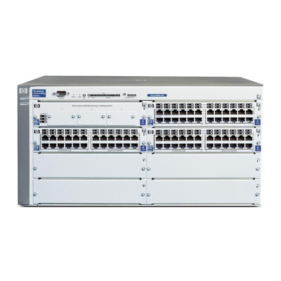
Page 12: Front Of The Switch
Introducing the HP ProCurve Series 4100gl Switches Front of the Switch Front of the Switch Status LEDs for the Fans, Power Supplies, Console and Switch Modules Port Power Reset and Clear LED Mode Select button and Fault buttons and indicator LEDs LEDs Self Test LED Switch Modules and slots... -
Page 13: Leds
Introducing the HP ProCurve Series 4100gl Switches Front of the Switch LEDs As described in the next two tables, there are LEDs on the switch chassis and on the switch modules that keep you informed of the status of the switch and the network connections. - Page 14 Introducing the HP ProCurve Series 4100gl Switches Front of the Switch LEDs State Meaning Status/ A module is installed in the switch module slot corresponding to the letter and the module Modules is undergoing or has passed self test. This also occurs when you install a module when (green - letters the switch is powered on (“hot swap”).
-
Page 15: Led Mode Select Button And Indicator Leds
Introducing the HP ProCurve Series 4100gl Switches Front of the Switch LED Mode Select Button and Indicator LEDs To optimize the amount of information that can be displayed for each of the switch ports, the Series 4100gl Switches use a Mode LED for each port. The operation of this LED is controlled by the LED Mode Select button on the switch chassis, and the current setting is indicated by the mode indicator LEDs near the button. -
Page 16: Console Port
Introducing the HP ProCurve Series 4100gl Switches Front of the Switch Console Port This port is used to connect a console to the switch by using the serial cable supplied with the switch. This connection is described under “Connecting a Console to the Switch”... -
Page 17: Back Of The Switch
Introducing the HP ProCurve Series 4100gl Switches Back of the Switch Back of the Switch slot for installing optional AC power connector redundant power supply Power Connector The Series 4100gl Switches do not have a power switch; they are powered on when connected to an active AC power source. -
Page 18: Switch Features
Introducing the HP ProCurve Series 4100gl Switches Switch Features Switch Features The features of the Series 4100gl Switches include: 4 or 8 slots for installing any of the available Switch gl Modules. Supported Modules: As of this printing, the supported gl modules includes: •... - Page 19 Introducing the HP ProCurve Series 4100gl Switches Switch Features easy management of the switch through several available interfaces: • web browser interface—an easy to use built-in graphical interface that can be accessed from common web browsers. • console interface—a full featured, easy to use, VT-100 terminal inter- face for out-of-band switch management, or for telnet access to the switch.
- Page 20 — This page is intentionally unused. —...
-
Page 21: Installing The Series 4100Gl Switches
Installing the Series 4100gl Switches The HP Series 4100gl Switches are easily installed. They come with an acces sory kit that includes the brackets for mounting the switch in a standard 19- inch telco rack, in an equipment cabinet, or on a wall. The switches have rubber feet already attached so they can be securely located on a horizontal surface. -
Page 22: Installation Procedures
Installing the Series 4100gl Switches Installation Procedures Installation Procedures Summary Follow these easy steps to install your switch. The rest of this chapter provides details on these steps. 1. Prepare the installation site (page 2-5). Ensure the physical environ ment into which you will be installing the switch is properly prepared including having the correct network cabling ready to connect to the switch, and having a good location for the switch. -
Page 23: Installation Precautions
Installing the Series 4100gl Switches Installation Procedures 7. Connect the network devices (page 2-18). Using the appropriate network cables, connect other switches, hubs, routers, computers, servers, printers, and other network devices to the switch ports. For more information, see “Connect the Network Devices” on page 2-18. -
Page 24: Installation Precautions (Continued)
Installing the Series 4100gl Switches Installation Procedures Installation Precautions (continued) C a u t i o n s Ensure the power source circuits are properly grounded, then use the power cord supplied with the switch to connect it to the power source. If your installation requires a different power cord than the one supplied with the switch and power supply, be sure the cord is adequately sized for the switch’s current requirements. -
Page 25: Prepare The Installation Site
Installing the Series 4100gl Switches Installation Procedures 1. Prepare the Installation Site Cabling Infrastructure Ensure the cabling infrastructure meets the necessary network specifications. See the following table for cable types and lengths, and see appendix B, “Cables and Connectors” for more information: Table 2-1. -
Page 26: Installation Location
Installing the Series 4100gl Switches Installation Procedures Port Type Cable Type Length Limits Fiber Optic Cables Gigabit-SX Multimode fiber-optic cables fitted with LC 220 meters to 550 meters depending on the (on Gigabit-SX-LC connectors cable used. See “Fiber-Optic Cables” on page mini-GBIC) for more information. -
Page 27: Install Switch Modules
Installing the Series 4100gl Switches Installation Procedures 2.Install Switch Modules Install switch modules into the slots as shown in the illustration below. For installation details, see the instructions in the manual that comes with the module. N o t e Ensure you install only HP ProCurve Switch gl Modules. - Page 28 Installing the Series 4100gl Switches Installation Procedures Insert module into the guides and slide it in until it is fully inserted. “Low-force” connector. High insertion force is not needed and should not be used. For best results, push near both screws. The module is fully inserted when the module bulkhead is contacting, or very close to contacting...
-
Page 29: Optional) Install Second Power Supply
Installing the Series 4100gl Switches Installation Procedures 3. (Optional) Install Second Power Supply A second, load-sharing redundant power supply (HP ProCurve Switch gl/xl RPS, HP J4839A) can be installed in the back of the switch. To provide true redundancy, this second power supply should be connected to a different AC power source from the other supply. - Page 30 Installing the Series 4100gl Switches Installation Procedures Insert the power supply into the opening, then slide it all the way in until it connects to the switch. The power supply face plate will be flush with the back face of the switch.
-
Page 31: Verify The Switch Passes Self Test
Installing the Series 4100gl Switches Installation Procedures 4. Verify the Switch Passes Self Test After you have installed any modules and the optional second power supply, but before mounting the switch in its network location, you should first verify that it is working properly by plugging it into a power source and verifying that it passes its self test. -
Page 32: Led Behavior
Installing the Series 4100gl Switches Installation Procedures Switch Chassis LEDs switch module LEDs: Link and Mode LEDs for each port When the switch is powered on, it performs its diagnostic self test. The entire download, initialization, and self test process can take up to 2 1/2 minutes for a fully loaded chassis, depending on the number and type of modules installed in the switch. -
Page 33: Mount The Switch
Installing the Series 4100gl Switches Installation Procedures The port LEDs on the switch modules go into their normal operational mode: If the ports are connected to active network devices, the Link LEDs • stay on and the Mode LEDs behave according to the mode selected. In the default mode (Activity), the Mode LEDs should flicker showing network activity on the port. - Page 34 Installing the Series 4100gl Switches Installation Procedures Attaching brackets to the 4-slot switches. 10 mm M4 screws Attaching brackets to the 8-slot switches. 10 mm M4 screws 2-14...
- Page 35 Installing the Series 4100gl Switches Installation Procedures Partially install a screw (5/8-inch number 12-24) into the top hole of a pair of holes that are 0.5 inches apart in each rack/cabinet upright as shown in the illustration below. Ensure the screws are at the same level in each upright.
-
Page 36: Horizontal Surface Mounting
Installing the Series 4100gl Switches Installation Procedures 4. Install the other number 12-24 screw into the upper hole in each bracket. Tighten these screws. install and tighten the other 12-24 screws E q u i p m e n t If you are installing the switch in an equipment cabinet, in place of the C a b i n e t 12-24 screws supplied with the switch, use the clips and screws that came with... -
Page 37: Wall Mounting
Installing the Series 4100gl Switches Installation Procedures Wall Mounting The mounting brackets supplied with the switch allow you to mount it on a wall. The illustrations below show mounting a Switch 4108gl. The Switch 4104gl and 4148gl would be mounted in a similar way. C a u t i o n For safe operation, do not install the switch with the vents or fans facing downward. -
Page 38: Connect The Switch To A Power Source
Installing the Series 4100gl Switches Installation Procedures 6. Connect the Switch to a Power Source Plug the included power cord into the switch’s power connector and into a nearby properly grounded AC power source. If you have installed a redundant power supply module into the switch, it should be connected to a separate AC power source. -
Page 39: Optional) Connect A Console To The Switch
Installing the Series 4100gl Switches Installation Procedures 8. (Optional) Connect a Console to the Switch The Series 4100gl Switches have a full-featured, easy to use console interface for performing the following tasks: Monitor switch and port status and observe network activity counters Modify the switch’s configuration Read the event log and access diagnostic tools to help in troubleshooting Download new software to the switch... -
Page 40: Direct Console Access
Installing the Series 4100gl Switches Installation Procedures If you want to operate the console using a different configuration, make sure you change the settings on both the terminal and on the switch. Change the switch settings first, then change the terminal settings, and reestablish the console session. -
Page 41: Hot Swapping Switch Modules
Installing the Series 4100gl Switches Hot Swapping Switch Modules If you want to continue with console management of the switch at this time through either a direct connection or a telnet session, see chapter 3, “Getting Started With Switch Configuration” for some basic configuration steps. For more detailed information, refer to the Management and Configuration Guide that is on the documentation CD-ROM that came with your switch. -
Page 42: Example Network Topologies
Installing the Series 4100gl Switches Example Network Topologies Example Network Topologies This section shows you a few example network topologies in which the Series 4100gl Switches can be implemented. For more topology information, see the HP network products World Wide Web site, http://www.hp.com/go/ hpprocurve. -
Page 43: Use As An Edge Switch
Installing the Series 4100gl Switches Example Network Topologies Use as an Edge Switch trunked HP ProCurve redundant Gigabit Routing Switch 9308 fiber-optic cables Switch 4108gl Switch 4108gl When your network expands and the users need to access resources beyond the edge of the local network, the Series 4100gl Switches are excellent platforms for that expansion. -
Page 44: Stacking The Switches
Installing the Series 4100gl Switches Example Network Topologies Stacking the Switches The Series 4100gl Switches can be connected together, through standard network connections, and managed through a single IP address. Up to 16 switches can be connected together in such a “virtual stack”. You identify one of the switches as the “Commander”... -
Page 45: Getting Started With Switch Configuration
Getting Started With Switch Configuration This chapter is a guide for using the console Switch Setup screen to quickly assign an IP (Internet Protocol) address and subnet mask to the switch, set a Manager password, and, optionally, configure other basic features. For more information on using the switch console and the other switch management interfaces: the web browser interface and the SNMP manage... -
Page 46: Using The Switch Setup Screen
Getting Started With Switch Configuration N o t e By default, the switch is configured to acquire an IP address configuration from a DHCP or Bootp server. To use DHCP/Bootp instead of the manual method described in this chapter, see “DHCP/Bootp Operation” in the Management and Configuration Guide that is on the documentation CD- ROM that came with your switch. - Page 47 Getting Started With Switch Configuration 4. ïï ïïïto the IP Config (DHCP/Bootp) field and use the Space bar to select the Manual option. 5. ïï ïïïto the IP Address field and enter the IP address that is compatible with your network. 6. ïï...
-
Page 48: Where To Go From Here
Getting Started With Switch Configuration The switch is now configured with a Manager password, IP address, and subnet mask. As a result, the switch can be accessed through your network using Telnet, the web browser interface, or an SNMP-based network manage ment tool such as HP ProCurve Manager for Hubs &... -
Page 49: Using The Ip Address For Remote Switch Management
Getting Started With Switch Configuration Using the IP Address for Remote Switch Management Using the IP Address for Remote Switch Management With your Series 4100gl Switches, you can use the switch’s IP address to manage the switch from any PC that is on the same subnet as the switch. You can use either a Telnet session or a standard web browser to manage the switch. - Page 50 Getting Started With Switch Configuration Using the IP Address for Remote Switch Management For more information on using the web browser interface, please see the Management and Configuration Guide that is on the documentation CD- ROM that came with your switch. An extensive help system is also available for the web browser interface.
-
Page 51: Troubleshooting
Troubleshooting This chapter describes how to troubleshoot your Series 4100gl Switches. This document describes troubleshooting mostly from a hardware perspective. You can perform more in-depth troubleshooting using the software tools available with the switch, including the full-featured console interface, the built-in web browser interface, and HP ProCurve Manager for Hubs &... - Page 52 Troubleshooting Basic Troubleshooting Tips Improper Network Topologies. It is important to make sure you have a valid network topology. Common topology faults include excessive cable length and excessive repeater delays between end nodes. If you have network problems after recent changes to the network, change back to the previous topology.
- Page 53 Troubleshooting Basic Troubleshooting Tips Connecting to devices that have a fixed full-duplex configuration. The RJ-45 ports on the Series 4100gl Switches are all configured as “Auto”. That is, when connecting to attached devices, the switch will operate in one of two ways to determine the link speed and the communication mode (half duplex or full duplex): •...
-
Page 54: Diagnosing With The Leds
Troubleshooting Diagnosing with the LEDs Diagnosing with the LEDs Table 4-1 shows LED patterns on the switch and the switch modules that indicate problem conditions. Check in the table for the LED pattern that you see on your switch Refer to the corresponding diagnostic tip on the next few pages. Table 4-1. - Page 55 Troubleshooting Diagnosing with the LEDs Diagnostic Tips: Number Problem Solution The power supplies 1. Verify the power cord is plugged into an active power source and to the switch. installed in the Ensure these connections are snug. switch are not 2.
- Page 56 As Hewlett-Packard introduces new modules for your HP ProCurve Switch gl, you may have to update the switch with new operating code that supports the new module. The documentation that came with the module will indicate which version of the operating code is needed to support the module.
- Page 57 Troubleshooting Diagnosing with the LEDs Number Problem Solution The network port During the module self test, described in tip number 4 earlier in this table, each for which the Link network port is also tested. If the port self test fails, the individual port is not usable, LED is flashing has but the rest of the ports on the module, which have passed their self test, will experienced a self...
- Page 58 Troubleshooting Diagnosing with the LEDs Number Problem Solution The network Try the following procedures: connection is not • For the indicated port, verify that both ends of the cabling, at the switch and the working properly. connected device, are securely connected. • Verify the connected device and switch are both powered on and operating correctly.
-
Page 59: Proactive Networking
Troubleshooting Proactive Networking Proactive Networking The Series 4100gl Switches have built-in management capabilities that proactively help you manage your network including: finding and helping you fix the most common network error conditions (for example, faulty network cabling, and non-standard network topolo gies) informing you of the problem with clear, easy-to-understand messages recommending network configuration changes to enhance the perfor... -
Page 60: Hardware Diagnostic Tests
Troubleshooting Hardware Diagnostic Tests Hardware Diagnostic Tests Testing the Switch by Resetting It If you believe that the switch is not operating correctly, you can reset the switch to test its circuitry and operating code. To reset a switch, either: Unplug and plug in the power cord (power cycling) Press the Reset button on the front of the switch Power cycling the switch and pressing the Reset button both cause the switch... -
Page 61: Testing Twisted-Pair Cabling
Troubleshooting Hardware Diagnostic Tests Testing Twisted-Pair Cabling If you think the cable should work but still isn’t working, it may not be compatible with the IEEE 802.3 Type 10Base-T, 100Base-TX, or 1000Base-T standards, as appropriate for the switch port type that the cable is connected to. -
Page 62: Restoring The Factory Default Configuration
Troubleshooting Restoring the Factory Default Configuration Restoring the Factory Default Configuration As part of your troubleshooting process, it may become necessary to return the switch configuration to the factory default settings. This process momen tarily interrupts the switch operation, clears any passwords, clears the console event log, resets the network counters to zero, performs a complete self test, and reboots the switch into its factory default configuration including deleting an IP address, if one is configured. -
Page 63: Downloading New Code
HP Customer Support Services If you are still having trouble with your switch, Hewlett-Packard offers support 24 hours a day, seven days a week through the use of a number of automated electronic services. See the Customer Support/Warranty booklet that came with your switch for information on how to use these services to get technical support. - Page 64 — This page is intentionally unused. —...
-
Page 65: Physical
Specifications Physical Width: 44.2 cm (17.2 in) Depth: 39.0 cm (15.2 in) Height: • Switch 4108gl and Bundle; • 22.5 cm (8.7 in) 4160gl • Switch 4104gl, 4148gl, and • 13.5 cm (5.2 in) 4140gl Weight: • Switch 4108gl • 11.6 kg (25.5 lbs) •... -
Page 66: Environmental
Specifications Environmental Operating Non-Operating Temperature: 0 C to 55 C (32 F to 131 F) -40 C to 70 C (-40 F to 158 F) Relative humidity: 15% to 95% at 40 C (104 F) 15% to 90% at 65 C (149 F) (non-condensing) Maximum altitude: 4.6 Km (15,000 ft) -
Page 67: Acoustic
Running H/F 1 Acoustic Switch 4108gl and Bundle; 4160gl: Geräuschemission LwA=53.0 dB am fiktiven Arbeitsplatz nach DIN 45635 T.19 Noise Emission LwA=53.0 dB in a virtual workspace according to DIN 45635 T.19 Switch 4104gl, 4148gl, and 4140gl: Geräuschemission LwA=56.0 dB am fiktiven Arbeitsplatz nach DIN 45635 T.19 Noise Emission LwA=56.0 dB in a virtual workspace according to DIN 45635 T.19... - Page 68 — This page is intentionally unused. —...
-
Page 69: B Switch Ports And Network Cables
Switch Ports and Network Cables This appendix includes switch connector information and network cable information for cables that should be used with the Series 4100gl Switches, including minimum pin-out information and specifications for twisted-pair cables. N o t e Incorrectly wired cabling is the most common cause of problems for LAN communications. -
Page 70: Cables
Switch Ports and Network Cables Cables Twisted-Pair 10 Mbps Operation Category 3, 4, or 5 100-ohm differential unshielded twisted- pair (UTP) or shielded twisted-pair (STP) cable, complying with IEEE 802.3 Type 10Base-T specifications, fitted with RJ-45 connectors. 100 Mbps Operation Category 5 100-ohm differential UTP or STP cable, complying with IEEE 802.3u 100Base-TX specifications, fitted with RJ-45 connectors. -
Page 71: Twisted-Pair Cable/Connector Pin-Outs
Switch Ports and Network Cables Twisted-Pair Cable/Connector Pin-Outs Fiber-Optic Cables Port Type Cable Specifications Connector Type Maximum Length Gigabit-SX 62.5/125 mm or 50/125 m (core/cladding) LC - Gigabit-SX • 62.5 m cable: diameter, graded-index, low metal content, mini-GBIC – 160 MHz*km=220 meters multimode fiber-optic cables, complying SC - Gigabit-SX –... - Page 72 Switch Ports and Network Cables Twisted-Pair Cable/Connector Pin-Outs N o t e HP Auto-MDIX was developed and shared with the IEEE for the development of the IEEE 802.3ab standard. HP Auto-MDIX and the IEEE 802.3ab Auto MDI/ MDI-X are completely compatible. If you connect a Series 4100gl Switch twisted-pair port to another switch or hub, which typically have MDI-X ports, the Series 4100gl Switch port automat ically operates as an MDI port.
-
Page 73: Straight-Through Twisted-Pair Cable For 10 Mbps Or 100 Mbps Network Connections
Switch Ports and Network Cables Twisted-Pair Cable/Connector Pin-Outs Straight-Through Twisted-Pair Cable for 10 Mbps or 100 Mbps Network Connections Because of the HP Auto-MDIX operation of the 10/100 ports on the switches, for all network connections, to PCs, servers or other end nodes, or to hubs or other switches, you can use straight-through cables. -
Page 74: Crossover Twisted-Pair Cable For 10 Mbps Or 100 Mbps Network Connection
Switch Ports and Network Cables Twisted-Pair Cable/Connector Pin-Outs Crossover Twisted-Pair Cable for 10 Mbps or 100 Mbps Network Connection The HP Auto-MDIX operation of the 10/100 ports on the switches also allows you to use crossover cables for all network connections, to PCs, servers or other end nodes, or to hubs or other switches. -
Page 75: Straight-Through Twisted-Pair Cable For 1000 Mbps Network Connections
Switch Ports and Network Cables Twisted-Pair Cable/Connector Pin-Outs Straight-Through Twisted-Pair Cable for 1000 Mbps Network Connections 1000Base-T connections require that all four pairs or wires be connected. Cable Diagram N o t e Pins 1 and 2 on connector “A” must be wired as a twisted pair to pins 1 and 2 on connector “B”. - Page 76 — This page is intentionally unused. —...
-
Page 77: C Safety And Emc Regulatory Statements
Safety and EMC Regulatory Statements Safety Information Documentation reference symbol. If the product is marked with this symbol, refer to the product documentation to get more information about the product. WARNING A WARNING in the manual denotes a hazard that can cause injury or death. -
Page 78: Informations Concernant La Sécurité
Safety and EMC Regulatory Statements Informations concernant la sécurité Informations concernant la sécurité Symbole de référence à la documentation. Si le produit est marqué de ce symbole, reportez-vous à la documentation du produit afin d'obtenir des informations plus détaillées. WARNING Dans la documentation, un WARNING indique un danger susceptible d'entraîner des dommages corporels ou la mort. -
Page 79: Hinweise Zur Sicherheit
Safety and EMC Regulatory Statements Hinweise zur Sicherheit Hinweise zur Sicherheit Symbol für Dokumentationsverweis. Wenn das Produkt mit diesem Symbol markiert ist, schlagen Sie bitte in der Produktdokumentation nach, um mehr Informationen über das Produkt zu erhalten. WARNING Symbol für Dokumentationsverweis. Wenn das Produkt mit diesem Symbol markiert ist, schlagen Sie bitte in der Produktdokumentation nach, um mehr Informationen über das Produkt zu erhalten. -
Page 80: Considerazioni Sulla Sicurezza
Safety and EMC Regulatory Statements Considerazioni sulla sicurezza Considerazioni sulla sicurezza Simbolo di riferimento alla documentazione. Se il prodotto è contras segnato da questo simbolo, fare riferimento alla documentazione sul prodotto per ulteriori informazioni su di esso. WARNING La dicitura WARNINGdenota un pericolo che può causare lesioni o morte. -
Page 81: Consideraciones Sobre Seguridad
Safety and EMC Regulatory Statements Consideraciones sobre seguridad Consideraciones sobre seguridad Símbolo de referencia a la documentación. Si el producto va marcado con este símbolo, consultar la documentación del producto a fin de obtener mayor información sobre el producto. WARNING Una WARNING en la documentación señala un riesgo que podría resultar en lesiones o la muerte. -
Page 82: Safety Information (Japan
Safety and EMC Regulatory Statements Safety Information (Japan) Safety Information (Japan) C-6... -
Page 83: Safety Information (China
Safety and EMC Regulatory Statements Safety Information (China) Safety Information (China) C-7... -
Page 84: Emc Regulatory Statements
Safety and EMC Regulatory Statements EMC Regulatory Statements EMC Regulatory Statements U.S.A. FCC Class A This equipment has been tested and found to comply with the limits for a Class A digital device, pursuant to Part 15 of the FCC Rules. These limits are designed to provide reasonable protection against interference when the equipment is operated in a commercial environment. -
Page 85: Korea
Series 4100gl Switches are assigned a Regulatory Model Number. The Regulatory Model Number for these switches is RSVLC-0201. This regulatory number should not be confused with the marketing name (HP ProCurve Series 4100gl Switches), or product numbers (J4861A, J4865A, J4887A, J4888A) -
Page 86: European Community
73/23/EEC and the EMC Directive 89/336/EEC and carries the CE mark. Tested with Hewlett-Packard Co. products only. Roseville, October 24, 2003 Mike Avery, Regulatory Engineering Manager European Contact: Your local Hewlett-Packard Sales and Service Office or Hewlett-Packard GmbH, Department TRE, Herrenberger Strasse 140, D-71034 Böblingen (FAX:+49-7031-14-3143). C-10... - Page 87 Index Numerics Bootp automatic switch configuration … 3-2 100/1000Base-T for in-band console access … 2-19 note on cable requirements … B-2 buttons ports, cables used with … B-2 Clear button … 1-8 twisted-pair cable specifications … B-2 LED Mode Select button … 1-7 1000Base-LH Reset button …...
- Page 88 cables, twisted pair console port category 3, 4, 5 … B-4 description … 1-8 connector pin-outs … B-3 location on switch … 1-4 crossover cable pin-out … B-6 crossover cable HP Auto-MDIX feature … B-3 pin-out … B-6 MDI-X to MDI connections … B-5, B-7 use with fixed port configurations …...
- Page 89 Fault LED behavior during self test … 2-12 in-band description … 1-5 console access, types of … 2-19 flashing definition … 1-6 managing the switch … 3-1 location on switch … 1-4 included parts … 2-1 showing error conditions … 4-4 installation FDx LED …...
- Page 90 showing error conditions … 4-4 on switch chassis … 1-5 network cables on switch modules … 1-6 1000Base-LH connections … 2-6 Power … 1-5 1000Base-LX connections … 2-6 behavior during error conditions … 4-4 1000Base-SX connections … 2-6 behavior during self test … 2-12 1000Base-T connections …...
- Page 91 Power LED selecting the Mode LED display … 1-7 behavior during error conditions … 4-4 self test behavior during self test … 2-12 Fault LED behavior … 2-12 description … 1-5 LED behavior during … 2-12 location on switch … 1-4 Power LED behavior …...
- Page 92 switch modules troubleshooting … 4-1 booting the switch to initialize changed module basic tips … 4-1 type … 2-7 checking port configuration … 4-3 hot swapping … 2-21 checking the console messages … 4-10 installing … 2-7 checking the LEDs … 4-10 LEDs descriptions …...
- Page 94 Technical information in this document is subject to change without notice. ©Copyright 2002, 2003 Hewlett-Packard Development Company, L.P. Reproduction, adaptation, or translation without prior written permission is prohibited except as allowed under the copyright laws. Printed in Singapore November 2003...
Need help?
Do you have a question about the J4865A and is the answer not in the manual?
Questions and answers