
Subscribe to Our Youtube Channel
Related Manuals for Algo 3226


Summary of Contents for Algo 3226
- Page 1 3226 Trunk Port FXO Doorphone Installation and User Guide Algo Communication Products Ltd., Burnaby, BC Canada V5J 5L2 www.algosolutions.com Document #: 90-00040E - 1 -...
-
Page 2: Support
Doorphone Controller must first be connected to a properly Earthed mains supply. Under no circumstances can the Doorphone Controller be disconnected from Earth ground while connected to outdoor wiring. The 3226 Trunk Port FXO Doorphone is not intended to be directly connected to public telecom networks. Support Algo is pleased to offer telephone or email support relating to installation issues, applications assistance, or general product inquiries. -
Page 3: Table Of Contents
Configuration Tool ........19 Related Algo Doorphone Products......20 8028 SIP Doorphone. -
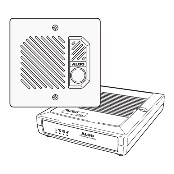
Page 4: Introduction
Introduction The 3226 Trunk Port FXO Doorphone connects to an FXO port of a gateway device, loop start trunk port of a telephone system, or a traditional POTS telephone When a visitor presses the Door Station call button, the 3226 Doorphone will ring... -
Page 5: Quick Install & Test
Quick Install & Test The 3226 Trunk Port FXO Doorphone is pre-configured for a typical installation. Programming is only required to change default setting or for more advanced applications. 1. Connect the power supply to the Power Jack of the Doorphone Controller and plug into an available AC outlet. -
Page 6: Application Basics
Application Basics The 3226 architecture and digital link between the Door Station and Controller provides flexible options using the auxiliary inputs and outputs. These are some typical applications: Cancel Ring When Door Opened In a residential or warehouse installation it is not uncommon for the door to be answered in person before the phone is answered. - Page 7 Anti-Door Tamper A feature of the 3226 Doorphone is to ring the telephone(s) with a warning alert in the event a door is ajar due to tampering (such as a door blocked open after being legitimately released for a visitor).
-
Page 8: Basic Wiring Setup
Basic Wiring Setup 3226 Doorphone Controller 24V 0.3A 24VDC 0.6A USB Configuration Door Control Relay - Port see Door Control Section Power Input 24 V 0.6 A Door Station Jack Telephone Jack. Connect to FXO Gateway, analog 6-Wire Modular Cable... -
Page 9: Programming & Configuration
Programming & Configuration The 3226 Trunk Port FXO Doorphone may be programmed either by DTMF or through software using the USB connection on the 3226 Controller. To enter Program Mode via the DTMF interface, dial **00 followed by the four digit password if configured (there is no password by default). - Page 10 Setting DTMF Description Default Name Code Open Code **31 LL S… LL = length of string (00 to 04) Digit 6 S… = numeric string (e.g. **31016 = “6”) Relay Time **32 nn nn=00: ¼ second nn=01..30: 1-30 seconds 3 sec Cancel with Door **33 nn nn=00: No...
- Page 11 Setting DTMF Description Default Name Code Max Door Open **51 nn nn=00: 30 sec nn=04: 60 min 07 None nn=01: 2 min nn=05: 90 min nn=02: 15 min nn=06: 120 min nn=03: 30 min nn=07: None Door Alarm **52 nn nn=00: Ring Phone every 6 seconds 04 None Security...
-
Page 12: Clid Character Table
CLID Character Table Code Char Code Char Code Char Code Char Code Char Space " & < > - 12 -... -
Page 13: Door Or Gate Control Basics
Door or Gate Control Basics Door control contacts are provided from the Doorphone Controller and are typically used for door strike activation or gate control. For security, the door control relay is located in the Controller to avoid entry by tampering. The Door Station dry contact output (OUT) may be configured for ‘low security’... -
Page 14: Power Supply
Power Supply The Doorphone Controller provides an auxiliary 24 V 0.3 A power supply which is suitable for common types of door strikes. If more current or a different voltage is required, then the customer must provide a matching power supply for the electric strike or magnetic lock. -
Page 15: Connections And Lights
Connections and Lights Auxiliary Dry Contact Outputs Both the Doorphone Controller and Door Station provide a dry contact output for connection to auxiliary devices. Maximum switching capacity is 30 V 50 Default operations are as follows: • Doorphone Controller Output = In-Use (commonly used for camera control) •... -
Page 16: Connection Details
Connection Details Door Control (5 Position Removable Terminal Block) Relay Normally Open 24V 0.3A Common Normally Closed Auxiliary PWR - 0.3 A (GND) Power PWR + 0.3 A (24 V) Door Station Jack (RJ12 Telephone Jack) Center Pair (Red & Green) Door Station Middle Pair (Yellow &... -
Page 17: Specifications
Specifications Telephone Interface Connect to analog telephone, FXO gateway, telephone system analog trunk port Ring Voltage 65 Vrms ring voltage 20 or 25 Hz Sinewave, REN=2 Talk Battery 48 Vdc, 30 mA current limit CLID GR-30-CORE, BT 227, and ETS 300 659-1 Ring Cadence Programmable Ring Persistence... - Page 18 Weather CSA/UL NEMA 3R weather resistant for outdoor locations Resistance Call Button Backlit tactile silicon rubber Installation Flush or surface mounted using supplied plastic bezel; Fits two gang electrical box Faceplates 304 Stainless Steel, Brass; Optional Vandal-Proof (model 3203) Programming Method DTMF or USB Port using configuration software Power Requirement...
-
Page 19: Configuration Tool
The USB Configuration Tool is a Windows software alternative to the DTMF programming method described earlier in this Guide. To use the Tool, first attach the supplied USB cable between the computer and the 3226, then install and run the software from the CD. -
Page 20: Related Algo Doorphone Products
Same as the model 8028 above with the exception that the supplied digital door station is a special tamper-proof design. Suitable for environments where there is a high potential for attempted damage or abuse. www.algosolutions.com/8028V Algo Communication Products Ltd., Burnaby, BC Canada V5J 5L2 www.algosolutions.com - 20 -...
Need help?
Do you have a question about the 3226 and is the answer not in the manual?
Questions and answers