Atlona AT-PROHD88M-SR User Manual
8x82 hdmi with ir matrix switcher over cat5
Hide thumbs
Also See for AT-PROHD88M-SR:
- User manual (14 pages) ,
- User manual (8 pages) ,
- User manual (25 pages)

Related Manuals for Atlona AT-PROHD88M-SR


Summary of Contents for Atlona AT-PROHD88M-SR
- Page 1 AtlonA HDMI with IR Matrix Switcher over CAT5 AT-PROHD88M-SR User Manual AT-PROHD88M-R FRONT VIEW AT-PROHD88M-S FRONT VIEW AT-PROHD88M-R REAR VIEW AT-PROHD88M-S REAR VIEW...
-
Page 2: Table Of Contents
5.2. Rear Panel ..........6. Connection and Operation ..........6.1. Operation on front panel ..........6.2. Control via RS232 ..........6.2.1. The Interface of AT-PROHD88M-SR ..........6.2.2. The Message Window ..........6.2.3. The Com Status ..........6.2.4. Control Command Format .......... -
Page 3: Introduction
INTRODUCTION Atlona’s AT-PROHD88M-SR is a true 8x8 HDMI matrix switcher. This unit allows any of the eight HD source’s (i.e. Blue-Ray player, HD DVD player, satellite receiver, PS3, AppleTV etc.) to be routed to any of the eight HD displays simultaneously. Users can choose several differ- ent ways of controlling the matrix: IR Back Channel, RS232, RS485, LAN and supplied remote control. -
Page 4: Specification
Note: Specifications are subject to change without notice. PACKAGE CONTENTS Master Unit 1. 1 x AT-PROHD88M-SR 2. 8 x IR emitter cables (marked IR TX), 3. 1x IR receiver cables (marked IR RX) 4. 1 x USB to RS232 cable 5. -
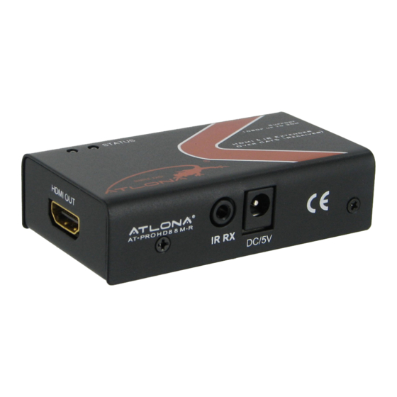
Page 5: Panel Descriptions
PANEL DESCRIPTIONS AT-PROHD88M-S Front Panel 1. Power switch. 2. Output selection push-buttons (Use it to choose the preferred output channel). 3. LED indicator of input for output port 1 to 8. 4. Action Confirmation Button (Push the ‘Enter’ button to confirm the changing of input channel to the output). 5. - Page 6 AT-PROHD-RP 1. HDMI output. 2. CAT-5e/6 input1 and input2. 3. Power input, 5VDC. (power supply is not required if used within suggested distance) 4. IR Receiver INPUT Note: IR emitter should be placed as near to the IR eye as possible.
-
Page 7: Connection And Operation
CONNECTION and OPERATION 1. Connect the HDMI input sources (such as HD-DVD, PS3, STB, AppleTV etc) into the AT-PROHD88M-SR. 2. Connect the standard HDMI outputs (such as LCD or DLP) into AT-PROHD88M-SR. 3. Connect two CAT-5E or CAT-6 cables to both Twisted Pair outputs of the unit and receiver Twister Pair inputs. -
Page 8: Control Via Rs232
3. Press the ‘Enter’ button to confirm the action. LED will stops blinking. the LED stops flashing press the enter push button to confirm the action 6.2. Control via RS232 6.2.1. The Interface of AT-PROHD88M-SR... -
Page 9: The Message Window
“operation results” such as below Status Button Click this button to read the status of AT-PROHD88M-SR. The status is about which input is selected by the output. Send Window Input the control command in this window. -
Page 10: The Com Status
Click this button to set the switch mode: Quick switch or Normal switch. When you click this button it will read the current mode of AT-PROHD88M-SR; if you want to change the mode, select the mode you want and click OK. -
Page 11: Control Command Format
”(hex: 63 69 72 20 33 39 0D 0A), when the unit receives this command ,it will change the Outport4 status to the next input port. ( “c”-0x63, ”I”-0x69, ”r”-0x72, ” “-0x20, ”3”- 0x33, ”9”-0x39, ‘ ’-0x0d0a) 6.2.5. Control code AT-PROHD88M-SR: Ouput1 <“08” >“09” 1“00” 2“01”... -
Page 12: Read Status Command
“bc” is the key word, ‘_’ is Space, ‘ ’ is carriage return. When you succeed in sending the read status command to the AT-PROHD88M-SR, it will feed- back the status of all outputs. When you send “Bc” to unit, it will feedback the current status of the switcher. -
Page 13: At-Prohd88M-Sr Rs-232 Remote
6.2.8. AT-PROHD88M-SR RS-232 Remote Control Protocol The connection between AT-PROHD88M-SR and remote controller with RS-232 modem cable AT-PROHD88M-SR Remote Controller Definition Definition RS-232 transmission format: Baud Rate : 9600 bps Data Bit : 8 bits Parity : None Stop Bit : 1 bit... - Page 14 cir 20 Output 3 select Input1 Output 3 cir 21 Output 3 select Input2 cir 22 Output 3 select Input3 cir 23 Output 3 select Input4 cir 24 Output 3 select Input5 cir 25 Output 3 select Input6 cir 26 Output 3 select Input7 cir 27 Output 3 select Input8...
- Page 15 cir 63 Output 7 select Input4 Output 7 cir 64 Output 7 select Input5 cir 65 Output 7 select Input6 cir 66 Output 7 select Input7 cir 67 Output 7 select Input8 < cir 68 Output 7 select Input previous >...
-
Page 16: Lan Control
6.3. LAN control Note:Use the direct UTP cable to connect with PC, or use cross cable to connect to the Ethernet switcher When NETCTL runs on PC for the first time, it will create a file ‘NETCTL.TXT’. This file is for device’s information backup. This information includes MAC address of unit, IP address, device name etc. - Page 17 The right area is for device controlling. Click these buttons to control the device. It is the same as using the remote controller. The left area shows which inputs are being chosen by the outputs. 3) When ‘Assign IP’ is displayed, it means that the device has not been assigned an IP au- tomatically.
-
Page 18: Ir Call-Back From Remote Locations To Control The At-Prohd88M-Sr
IR Call-back from Remote Locations to Control the AT-PROHD88M-SR You can use the unit’s remote through the IR RX of the HDMI receiver to change the input channel for the UTP out of the switcher, just by changing this UTP output. -
Page 19: Ir Cqdes
IR CODES More advanced users can program the following codes into the IR control systems or universal/ learning remote controls. input 1 input 2 input 3 input 4 input 5 input 6 input 7 input 8 output 1 output 2 output 3 output 4 output 5... -
Page 20: Details On The Edid
EDID will be copied to (Assumed as INPUT_N). Control the matrix to connect them. 2. Under AT-PROHD88M-SR’s normal working condition, push ‘ENTER’ and ‘OUTPUT_N’ simultaneously. Within two seconds the LEDs will light the character ‘-‘ circularly (This means the EDID COPY is auto running). - Page 21 select input 8 channel for output 1 3. Press down ‘ENTER’ and ‘OUTPUT_1’ simultaneously; after two seconds LED light show ‘-‘ circularly. (This means the matrix is performing EDID COPY). Release the buttons and wait for the machine to finish the remaining work. press output 1 button and enter button at the same time 4.
-
Page 22: Maintenance
Clean switcher with a soft, dry cloth. Never use alcohol, paint thinner or other chemicals to clean this unit. PRODUCT SERVICE Damage requiring service: The unit should be serviced by qualified Atlona service personnel if: 1. The DC power supply cord or AC adaptor has been damaged;... -
Page 23: Connection Diagram
CONNECTION DIAGRAM SOURCES 1 to 8 X-Box PS 3 HDMI cable HDMI cable 2xCAT5e cable 2xCAT5e cable AT-PROHD-RP (optional accessory) AT-PROHD88M-R AT-PROHD88M-R HDMI cable HDMI cable HDTV HDTV... -
Page 24: Safety Information
Use only accessories recommended by ATLONA to avoid fire, shock or other Do not modify the wall plug. hazards. Doing so will void the warranty and safety features. -
Page 25: Warranty
Product, or repair or replacement of the Product that does not meet this Limited Warranty and which is returned to Atlona Technologies with a copy of Customer’s receipt. This Limited Warranty is void if failure of the Product has resulted from accident, abuse, or misapplication. -
Page 26: Atlona Product Registration
At Atlona, we respect and protect your privacy and assure you that your registration information is completely secure. Of course, Atlona product registration is totally voluntary and failure to register will not diminish your limited warranty rights. To register go to www.atlona.com/registration...
Need help?
Do you have a question about the AT-PROHD88M-SR and is the answer not in the manual?
Questions and answers