
Related Manuals for BK Medical 8570


Summary of Contents for BK Medical 8570
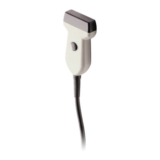
- Page 1 Linear Array Transducer User Guide Types 8570 and 8670 English BB1064-D April 2007...
- Page 2 If you receive an email message from us asking for your feedback, we hope you will be willing to answer some questions about your experience buying and using our products. Your opinions are important to us. You are of course always welcome to contact us via your BK Medical representative or by contacting us directly.
-
Page 3: Table Of Contents
Linear Array Transducer Types 8570 and 8670 Introduction Scanning Plane General Information Service and Repair Caring for the Transducer Cleaning and Disinfection Starting Scanning Connecting the Transducer Changing Frequency Using a Transducer Cover Using the Transducer Control Button Changing Orientation... -
Page 5: Linear Array Transducer Types 8570 And
Linear Array Transducer Types 8570 and 8670 Linear Array Transducer Types 8570 and 8670 Introduction This is the user guide for Linear Array Transducer Types 8570 and 8670 and must be used together with Transducer Care, Cleaning & Safety which contains important safety information. -
Page 6: General Information
8570 and 8670 • General Information Fig. 3. Scanning plane of 8670 with expanded sector (with the Pro Focus 2202 ultrasound scanner) General Information Product specifications for this transducer can be found in the Product Data sheet that accompanies this user guide. -
Page 7: Service And Repair
8570 and 8670 • Cleaning and Disinfection Service and Repair WARNING Service and repair of B-K Medical electromedical equipment must be carried out only by the manufacturer or its authorized representatives. B-K Medical reserves the right to disclaim all responsibility for the operating safety, reliability and performance of equipment serviced or repaired by other parties. -
Page 8: Changing Frequency
8570 and 8670 • Starting Scanning When connected the transducer complies with Type B requirements of EN60601-1 (IEC 60601-1). Changing Frequency The Multi-Frequency Imaging (MFI) facility enables you to select the scanning frequency. See the applicable scanner user guide for instructions. The selected frequency is displayed at the top of the screen. -
Page 9: Puncture Facilities
8570 and 8670 • Puncture Facilities Puncture Facilities Puncture and biopsy is possible with Types 8570 and 8670. The puncture attachment is illustrated in the following pages with a brief description of its use and operating instructions.. WARNING It is essential for the patient’s safety that only the correct puncture attachment is used with Types 8570 and 8670. -
Page 10: Ua1246
8570 and 8670 • Puncture Facilities Fig. 5. Puncture guide UA1269 mounted on 8670 There are three different angles of insertion available; 30°, 45° and 60°. To help you estimate the depth of needle penetration, the puncture line pattern is shown on the scanner (see Fig. - Page 11 (see Fig. 8.) the distance between each dot is 5 mm. Fig. 7. Puncture Guide UA1246 mounted on the 8570 To mount the needle puncture guide attachment: 1. Hold the transducer so that the vertical grooved edge is facing to the right and the cable is facing down.
-
Page 12: Performing Puncture And Biopsy
If the needle guide is detached from the transducer during interventional procedures, cover the transducer with a new transducer cover. To remove the puncture line from the scan image, refer to the applicable scanner user guide for instructions. Fig. 8. Puncture line for UA1246 on Types 8570 and 8670... -
Page 13: Cleaning After Puncture And Biopsy
8570 and 8670 • Disposal Fig. 9. Puncture lines for UA1249 with 8670 WARNING When performing a biopsy, always make sure that the needle is fully drawn back inside the needle guide before moving the probe. Cleaning after Puncture and Biopsy If biological materials are allowed to dry on the transducer or puncture attachments, disinfection and sterilization processes may not be effective.
Need help?
Do you have a question about the 8570 and is the answer not in the manual?
Questions and answers