
Related Manuals for Network Technologies VEEMUX SM-8X4-HDA


Summary of Contents for Network Technologies VEEMUX SM-8X4-HDA
- Page 1 ® VEEMUX Series SM-8X4-HDA Audio/HD Video Matrix Switch Installation and Operation Manual MAN066 Rev Date 5/19/2008...
- Page 2 Network Technologies Inc, 1275 Danner Drive, Aurora, Ohio 44202. CHANGES The material in this guide is for information only and is subject to change without notice. Network Technologies Inc reserves the right to make changes in the product design without reservation and without notification to its users.
-
Page 3: Table Of Contents
TABLE OF CONTENTS Introduction..................................1 Materials ..................................1 Cables..................................1 Default User Name and Passwords ..........................1 Features and Functions..............................2 Installation..................................3 Connect the Sources ..............................3 Connect the Devices..............................4 Connect RS232 ................................5 Connect to the Ethernet............................... 5 Power Up .................................. - Page 4 Update Firmware ..............................29 Change Password Page............................30 Help Page ................................30 Update Web Server ............................. 30 Logout Page ................................ 30 Device Discovery Tool ..............................31 Infrared Control ................................32 Features And Functions............................. 32 Keypad..................................32 LCD Display ................................32 How To Use The IRT ..............................
-
Page 5: Introduction
NTI AUDIO/HD VIDEO MATRIX SWITCH INTRODUCTION The VEEMUX SM-8X4-HDA (VEEMUX-A) is a versatile multi-input audio/video matrix switch that independently switches eight sets of incoming YPbPr component video and analog/digital audio signals to any or all of the four outputs. Each input and output has YPbPr component video, L/R analog audio (balanced/unbalanced), and digital audio on coax (S/PDIF). -
Page 6: Features And Functions
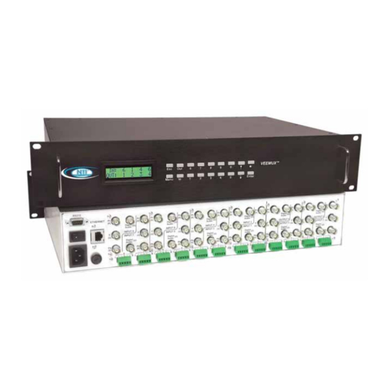
NTI AUDIO/HD VIDEO MATRIX SWITCH FEATURES AND FUNCTIONS Front View of VEEMUX-A VEEMUX Network Tech nologies Inc ENTER MENU Rear View of VEEMUX-A RS232 ETHERNET Digital Digital Digital Digital Digital Digital Audio Audio Audio Audio Audio Audio INPUT 8 INPUT 6 INPUT 4 INPUT 2 OUTPUT 4... -
Page 7: Installation
NTI AUDIO/HD VIDEO MATRIX SWITCH INSTALLATION Connect the Sources Turn OFF power to all video sources (inputs) that will be connected to the VEEMUX-A before connecting or disconnecting any cables. Connect each video source to the VEEMUX-A using 4CEXT-xx BNC cables. The groups of terminals are labeled INPUT1-8. and colored cables attach to terminals as follows: green (Y), blue (Pb) and red (Pr). -
Page 8: Connect The Devices
NTI AUDIO/HD VIDEO MATRIX SWITCH Jumper Jumper Wire Wire R+ R- L+ L- Connections for Connections for unbalanced stereo balanced stereo audio audio Figure 2- Stereo audio connection block Connect the Devices 1. Connect each of the video display devices to the VEEMUX-A using 3CEXT-xx or 4CEXT-xx cables. The groups of terminals are labeled OUTPUT1-4. -
Page 9: Connect Rs232
NTI AUDIO/HD VIDEO MATRIX SWITCH Connect RS232 RS232 control can be achieved using a separate user terminal or CPU with a terminal program. To make a terminal connection, connect a serial cable (specifications on page 39) between the user terminal and the 9 pin DIN female connector on the VEEMUX-A labeled "RS232". -
Page 10: Power Up
NTI AUDIO/HD VIDEO MATRIX SWITCH Power Up Connect the IEC power cord to the VEEMUX-A and plug the cord into an AC power outlet. Turn ON power to the VEEMUX-A using the switch above the IEC socket. Turn ON power to the video and audio sources, and the video and audio devices connected to the VEEMUX-A, if they are not already ON. -
Page 11: Control Options
NTI AUDIO/HD VIDEO MATRIX SWITCH CONTROL OPTIONS The VEEMUX-A video matrix switch has four methods of control: • Front Panel LCD with Keypad • Directly via an RS232 Interface • Remotely via Ethernet (web interface) • Infrared Remote (optional) Every unit comes standard with the Front Panel LCD with Keypad, RS232, and Ethernet connection built-in. If desired, the Infrared option must be requested at the time of the order. -
Page 12: Volume Control
NTI AUDIO/HD VIDEO MATRIX SWITCH Volume Control The volume level can be adjusted on each output port. To increment <▲> or decrement <▼> the volume, use the following command: • <OUT>, <▼>, Double digit output port number, <▲> increment or <▼> decrement, <ENTER> Ex 1: <OUT>... -
Page 13: Scan Mode
NTI AUDIO/HD VIDEO MATRIX SWITCH Scan Mode Scan Mode causes output ports (audio and video) to automatically switch from one audio and video input port to the next consecutive audio and video input port after a specified period of time (referred to as the dwell time). Audio and video port switching will continue indefinitely and no ports will be skipped, whether there are audio or video sources connected to them or not. -
Page 14: Rs232 Control
NTI AUDIO/HD VIDEO MATRIX SWITCH RS232 CONTROL RS232 enables the VEEMUX to be remotely controlled via RS232. To control the VEEMUX via RS232 the user has three options: • write a program that runs on a PC using the Command Protocol (page 11) •... -
Page 15: Command Protocol
NTI AUDIO/HD VIDEO MATRIX SWITCH Command Protocol CPU controller commands supported by the unit are defined below. All commands must be terminated with a <CR> (carriage return). When a command is sent, the entire string is echoed back along with a response from the addressed unit as shown in the Command Definitions table (below). -
Page 16: Autostatus
NTI AUDIO/HD VIDEO MATRIX SWITCH Command Definitions (Continued) Command String Good Response Description SS SW,00 *<CR> Disable Autostatus feature (see below) SS SW,01 *<CR> Enable Autostatus feature (see below) GO SW,OP *<CR>go Read connection of a Video Output Port to Video Input Port SW,OP,IP<CR>... -
Page 17: Matrix Switcher's Control Program For Windows 9X, Nt, 2000 And Xp
NTI AUDIO/HD VIDEO MATRIX SWITCH Matrix Switcher's Control Program For Windows 9X, NT, 2000 AND XP The Matrix Switcher's Control Program is an easy and powerful graphical program that controls NTI matrix switches through an RS232 interface. The Matrix Switcher's Control Program is included on the CD packaged with the VEEMUX-A. The Matrix Switcher's Control Program is downloaded by clicking on the link "Download Matrix Switcher's Control Program"... -
Page 18: Ethernet Operations
NTI AUDIO/HD VIDEO MATRIX SWITCH Ethernet Operations Selection Description Set Unit IP Address - enter the desired IP address in xxx.xxx.xxx.xxx format - number of digits is minimum 1 and maximum 3 for each field. Leading zeroes are accepted Set Unit Subnet Mask - enter the desired IP address in xxx.xxx.xxx.xxx format - number of digits is minimum 1 and maximum 3 for each field. - Page 19 NTI AUDIO/HD VIDEO MATRIX SWITCH The following commands are now available: Command Reply Description H(elp) or Displays the list of commands Help h(elp) CS nn,mm *<CR> Connect One Output nn To Input mm CA nn *<CR> Connect All Outputs To Input nn Read Connection For Output.
-
Page 20: Telnet Interface-Port 2005
NTI AUDIO/HD VIDEO MATRIX SWITCH Telnet Interface-Port 2005 For a software control type of telnet interface session (versus operator telnet control through port 2000 as described on page 14), connect to the VEEMUX through the current IP address at port 2005. To do this, a connection to port 2005 must first be enabled (see Web Setup on page 25). -
Page 21: Command Detail
NTI AUDIO/HD VIDEO MATRIX SWITCH Command Detail RU-Read Unit Size Command: Byte 1 Byte2 Byte3 ‘R’ ‘U’ <CR> (0x52) (0x55) (0x0D) Response: Byte 1 Byte 2 Byte 3 Byte 4 Byte 5 Byte 6 Byte 7 Byte 8 Byte 9 ‘r’... -
Page 22: Ss_01- Enable Auto Status Mode
NTI AUDIO/HD VIDEO MATRIX SWITCH SS_01- Enable Auto Status Mode Command: Byte 1 Byte 2 Byte 3 Byte 4 Byte 5 Byte 6 ‘S’ ‘S’ Space ‘0’ ‘1’ <CR> (0x53) (0x53) (0x20) (0x30) (0x31) (0x0D) Response: Byte 1 Byte 2 <CR>... -
Page 23: Ao-Read Audio Connection For Output Port
NTI AUDIO/HD VIDEO MATRIX SWITCH AO-Read Audio Connection for Output Port Command: Byte 1 Byte 2 Byte 3 Byte 4 Byte 5 Byte 6 ‘A’ ‘O’ Space Output – first digit Output – second digit <CR> (0x41) (0x4F) (0x20) (0x30…0x32) (0x30…0x39) (0x0D) Response:... -
Page 24: Av- Set Audio Volume For Output Port
NTI AUDIO/HD VIDEO MATRIX SWITCH AV- Set Audio Volume for Output Port Command: Byte 1 Byte 2 Byte 3 Byte 4 Byte 5 Byte 6 Byte 7 Byte 8 Byte 9 ‘A’ ‘V’ Space Output – 1st digit Output – 2nd digit ‘,’... -
Page 25: Ar- Read Mute And Volume For Audio Output Port
NTI AUDIO/HD VIDEO MATRIX SWITCH AR- Read Mute and Volume for Audio Output Port Command: Byte 1 Byte 2 Byte 3 Byte 4 Byte 5 Byte 6 ‘A’ ‘R’ Space Output – first digit Output – second digit <CR> (0x41) (0x52) (0x20) (0x30…0x32) -
Page 26: Web Interface
NTI AUDIO/HD VIDEO MATRIX SWITCH Web Interface A user may control the connections of the VEEMUX-A using a Web Interface via any web browser (see page 1 for web supported browsers). With the VEEMUX-A connected to a LAN through an Ethernet cable, a user can access the web interface controls inside the VEEMUX-A. -
Page 27: Video Switch Page
NTI AUDIO/HD VIDEO MATRIX SWITCH Video Switch Page The Video Switch page (right) displays the active connections (shown in orange) and enables the user to control the audio and video connections of the VEEMUX-A, or just the video. (To change audio connections separately, see page 24.) Up to 100 different connection configurations can be saved and later recalled by any connection method. -
Page 28: Audio Switch Page
NTI AUDIO/HD VIDEO MATRIX SWITCH To change video only, or audio and video, either leave the "Video + Audio" block empty (to effect only video) or use the mouse to place a check in the box shown to the right (to effect audio and video connections). -
Page 29: Setup Pages
NTI AUDIO/HD VIDEO MATRIX SWITCH Serial Data (VV) Audio Volume Serial Data (VV) Audio Volume 90-99 +10dB -40dB -50dB -10dB -60dB -20dB -70dB -30dB -80dB Place a checkmark in the Mute box for any output port where no volume is desired. Setup Pages These settings enable the user to configure the VEEMUX-A web interface connection. -
Page 30: Input Names
NTI AUDIO/HD VIDEO MATRIX SWITCH Figure 13- Web interface Serial Setup page Changes to the Serial Address and Serial Speed (Fig. 13) do not require a reset and will take effect immediately. Input Names Note: Only the changes to the port directly to the left of the Save button will be saved. -
Page 31: Output Names
NTI AUDIO/HD VIDEO MATRIX SWITCH Output Names From the Administration menu, the Video or Audio Output Names page can be displayed. (Selected separately from the menu.) These pages enable the Administrator to change the names of the output ports displayed on the Switch page. - Page 32 NTI AUDIO/HD VIDEO MATRIX SWITCH The output selection at the top of the page can be changed to any output to display the Scan Sequence Input selections and dwell times for that output. The inputs and the amount of time that each will be viewed (0-32000 seconds) can be set to cycle sequentially for each connected output.
-
Page 33: Update Firmware
NTI AUDIO/HD VIDEO MATRIX SWITCH Update Firmware For updating the Ethernet Control, use this section and insert the file v1_x.bin For updating the Front Panel LCD, use this section and insert the file rmtlcd_va_1_x. hex Figure 17- Web interface Update Firmware page The Update Firmware page (found in the main menu under "ADMINISTRATION") shows the current version of the firmware for the Web interface (Fig-17-upper) and for the Front panel (Fig-17-lower) and enables the Administrator to update the firmware of the VEEMUX-A. -
Page 34: Change Password Page
NTI AUDIO/HD VIDEO MATRIX SWITCH Change Password Page Use this page to change the password for accessing the web interface. (This password is also used for the telnet interface.) Be sure to make note of the new password exactly as it is case sensitive. -
Page 35: Device Discovery Tool
NTI AUDIO/HD VIDEO MATRIX SWITCH DEVICE DISCOVERY TOOL In order to easily locate the VEEMUX-A on a network, and change the IP settings, the NTI Device Discovery Tool may be used. A link to the Discovery Tool is provided on the web page that appears when you insert the instruction manual CD provided into your CD ROM drive. -
Page 36: Infrared Control
Unless otherwise specified, by default, all IRT-enabled switches will be configured as switch #1. Materials included: • IRT-64X32 Infrared Remote Transmitter for video matrix switches • (2) AA Cell Batteries- installed Network Technologies Inc Features And Functions Lo Batt Keypad Buttons Numbered 0-9 – Used for port selection OUT –... -
Page 37: How To Use The Irt
NTI AUDIO/HD VIDEO MATRIX SWITCH How To Use The IRT The IRT-64X32 enables the user to control the connections of up to 32 input ports and 16 output ports on up to four (4) separate NTI video matrix switches. When any key is pressed, the IRT will power ON. A number key should always be pressed first unless a change to the configuration is desired (see "Set Configuration"... -
Page 38: Change Output Port
NTI AUDIO/HD VIDEO MATRIX SWITCH Change Output Port Press the desired port number. If there is no change in the desired output port, the output port must still be selected. As the digits are selected, the last number entered will blink. The LCD will also display the current switch number followed by the decimal point. -
Page 39: Set Configuration
NTI AUDIO/HD VIDEO MATRIX SWITCH Set Configuration The IRT-64x32 factory default setting is 32 inputs and 16 outputs. When the batteries are changed the setting will return to the default value. At the default setting the IRT has the ability control any matrix switch with up to 32 inputs and 16 outputs without changing the configuration. -
Page 40: Battery Replacement
NTI AUDIO/HD VIDEO MATRIX SWITCH Battery Replacement The IRT has a low-battery indicator to let the user know when it is time to change the batteries. The right-hand decimal point in the LCD display will illuminate (see illustration below). This will stay illuminated while the IRT is in use until the batteries are changed or the battery charge is too low for the IRT to operate. -
Page 41: Rs232 Upgrade Of The Front Panel Lcd Firmware
HyperTerminal has been configured for connection through the correct COM port on the PC. With the HyperTerminal window open, hold the spacebar and apply power to the VEEMUX-A. A command menu and the Command prompt (>) should appear. Copyright 2006 Network Technologies Inc Flash Loader Utility v1.0 Display this help menu Clear flash Load flash with .hex file... - Page 42 NTI AUDIO/HD VIDEO MATRIX SWITCH Press <L> to load the firmware (hex) file. This will prepare the file for transfer to the VEEMUX-A. If the file fails to load, press the <C> key to clear the old firmware, and press <L> to load it again. When the message “Start sending file via Xmodem protocol..”' appears, the VEEMUX-A is waiting for the Firmware file to be uploaded.
-
Page 43: Rs232 Connection Cables
NTI AUDIO/HD VIDEO MATRIX SWITCH RS232 CONNECTION CABLES Pinout of RS232 port on VEEMUX-A The VEEMUX-A RS232 serial port is a DB-9F (female) connector configured as a DCE (data communication equipment) port. The RS232 port interface signals are listed below, including equivalent CCITT V.24 identification, and signal direction: DB-9F Common CCITT... -
Page 44: Pinout For Matrix Y-1 Cable
NTI AUDIO/HD VIDEO MATRIX SWITCH Pinout for Matrix Y-1 Cable Wiring Schematic of Matrix-Y-1 cable 9D Male 9D Female 9D Male (Unit #1) (Source) (Unit #2) Not connected to source connector Jumper Jumpers Arrows indicate signal direction. Figure 22- Pinout for Matrix Y-1 Cable RACK MOUNTING INSTRUCTIONS This NTI switch was designed to be directly mounted to a rack. -
Page 45: Specifications
NTI AUDIO/HD VIDEO MATRIX SWITCH SPECIFICATIONS DESCRIPTION SPECIFICATION Video Video Connectors Maximum Resolution 1920X1080@ 60Hz Supported Signals Component video, S-video, Composite video Input/Output Impedance 75 ohm Maximum Input / Output Levels 1.7Vp-p, no DC offset Gain Unity DC offset (output) +/- 15mV;... -
Page 46: Troubleshooting
NTI AUDIO/HD VIDEO MATRIX SWITCH TROUBLESHOOTING Problem Solution No Video Check power – power ON, power cable connected Check video cabling – make sure cables are secured Check connections – make sure you’re connected to an active input No Audio Check power –... -
Page 47: Index
NTI AUDIO/HD VIDEO MATRIX SWITCH INDEX address, 10 methods of control, 7 Audio Switch, 25 mount to a rack, 41 batteries, 37 password, 1 baud rate, 10 RS232 control, 5, 10 cables, 40 safety statements, 43 change the batteries, 37 Scan Mode, 9 control_options, 7 Scanning Sequences, 28...
Need help?
Do you have a question about the VEEMUX SM-8X4-HDA and is the answer not in the manual?
Questions and answers