
Subscribe to Our Youtube Channel
Related Manuals for Lilin CMR70823.6 N/P


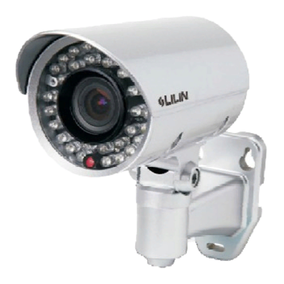
Summary of Contents for Lilin CMR70823.6 N/P
- Page 1 D/N ATR 700TVL IR CAMERA CMR7082/7084/7088 N/P 3.6/6 D/N ATR 700TVL VARI-FOCAL IR CAMERA CMR7082X3.6 N/P INSTRUCTION MANUAL...
- Page 2 IMPORTANT SAFEGUARDS CAUTION RISK OF ELECTRIC SHOCK DO NOT OPEN CAUTION TO REDUCE THE RISK OF ELECTRIC SHOCK, DO NOT REMOVE COVER (OR BACK) NO USER SERVICEABLE PARTS INSIDE. REFER SERVICING TO QUALIFIED SERVICE PERSONNEL. GRAPHIC SYMBOL EXPLANATION The lightning flash with arrowhead symbol, within an equilateral triangle, is intended to alert the user to the presence of uninsulated "dangerous voltage"...
- Page 3 CAUTION Do not drop or strike this equipment. Sensitive electronics inside are vulnerable to excessive shock. Do not install the equipment near any naked flames or heat sources. Excessive heat could damage this unit. Do not expose this unit to rain or excessive moisture, avoid smoke and dust.
- Page 4 CONGRATULATIONS Thank you for purchasing this D/N ATR 700TVL (Vari-Focal)IR Camera. You now own one of the many fine CCTV products we manufactured. This product has been carefully inspected under rigid quality control and should reach you in perfect condition. With reasonable care, it will provide years of reliable performance.
-
Page 5: Warranty Information
WARRANTY INFORMATION Please complete the following product purchase information. The factory will requests this information when contacted for technical support, or warranty repair. It is also valuable in case of loss or theft. Purchase Date Serial Number Model Number... -
Page 6: Table Of Contents
TABLE OF CONTENTS PART DESCRIPTION & DIMENSION INSTALLATION CONFIGURATION OF THE MENU SETTING MENU AND FUNCTION To Open and Exit the Menu screen LENS SHUTTER/AGC WHITE BAL (White Balance) BACKLIGHT (Backlight Compensation) PICT ADJUST (Picture Adjust) ATR (Adaptive Tone Reproduction) PRIVACY NR (Noise Reduction) CAMERA ID... -
Page 7: Part Description & Dimension
PART DESCRIPTION & DIMENSION 72.5 Unit: mm TOP COVER BOTTOM CHASSIS BRACKET PAN ADJUSTMENT SCREW TILT ADJUSTMENT SCREW WINDOW VIDEO OUTPUT JACK (CMR7082) DC POWER INPUT JACK ( DC12V 10%, CMR7082... -
Page 8: Installation
INSTALLATION 1. CMR7082 1-1. Take out the camera from the inner box first. Plug the video cable and power cable to video output jack and DC power input jack of the camera (FIG.1). Then fix bracket to the wall(FIG.2). DC power input Video output FIG. - Page 9 FIG. 4 FIG. 6 FIG. 5 2-2. Open the top cover with screw driver(FIG.7). FIG. 7 2-3. Next, Put the power cable and video cable through the bottom chassis and rubble(FIG.8) and then fix the camera body on the bracket(FIG.9).
- Page 10 FIG. 9 FIG. 8 2-4. Plug and fix the power cable to the terminal and plug the video cable to vidoe output of the camera(FIG.10). Also for the security, please use the adhesive tape to wrap the connection of video cable(FIG.11). Video Output Video Cable FIG.
- Page 11 FIG. 12 4. First, adjust the lens on focus and zoom to form the optimal video image after that tighten the screws(FIG.13). Then adjust the OSD menu to form the optimal image. Please refer to page7~19. LEFT RIGHT DOWN FOCUS ZOOM FIG.
- Page 12 (RIGHT) : Press to move the cursor to the right and select or adjust the parameters of the selected item. The parameters changes each time this button is pressed. : Press to move the cursor downwards or to select (DOWN) items.
-
Page 13: Configuration Of The Menu
CONFIGURATION OF THE MENU SETUP LENS AUTO TYPE DC MENU MANUAL MODE AUTO OPEN CLOSE SPEED(000~255) SHUTTER/ AUTO HIGH LUMINANCE MODE AUTO IRIS SHUT+AUTO IRIS BRIGHTNESS(000~255) LOW LUMINANCE MODE AGC OFF BRIGHTNESS x0.25 x0.50 x0.75 x1.00 MANUAL MODE SHUT+AGC SHUTTER 1/60(1/50) 1/100(1/120) 1/250~1/10000 AGC 6.00 12.00 18.00 24.00 30.00 36.00 42.00 44.80 WHITE BAL SPEED(000~255) - Page 14 PRIVACY AREA SEL 1/8~8/8 [000~244(NTSC), 000~288(PAL)] BOTTOM [000~244(NTSC), 000~288(PAL)] LEFT [000~474(NTSC), 000~468(PAL)] RIGHT [000~474(NTSC), 000~468(PAL)] COLOR(1~8) TRANSP 0.00 0.50 0.75 1.00 MOSAIC OFF ON NR MODE Y/C OFF/ Y/ C Y LEVEL(000~015) C LEVEL(000~015) CAMERA ID SYNC INT LANGUAGE ENGLISH DEUTSCH FRANCAIS PYCCK PORTUGUES ESPANOL...
-
Page 15: Setting Menu And Function
SETTING MENU AND FUNCTION TO Open and Exit the Menu screen 1. Press "SET" button. The Menu screen appears on the monitor. Check the current settings on the menu. 2. Push or button to select the options then use or button to select a mode. -
Page 16: Shutter/Agc
AUTO (AUTO IRIS) FUNCTION OPTION DESCRIPTION TYPE Sets the type of mechanical iris. DC: Direct drive signal. MODE AUTO Sets the type of control to be exercised over OPEN the mechanical iris. CLOSE AUTO: The mechanical iris is controlled automatically. OPEN: The mechanical iris is fixed to open. - Page 17 AUTO (AE) FUNCTION OPTION DESCRIPTION HIGH MODE AUTO IRIS Specifies AE control on the medium LUMINANCE SHUT+AUTO IRIS and high brightness side. AUTO IRIS: Fixed electronic shutter. [1/60sec.(NTSC), 1/50sec.(PAL)] SHUT+AUTO IRIS: Auto electronic shutter. [1/60sec.(1/50sec.)~1/100,000sec.] BRIGHTNESS 000~255 Specifies the medium and high brightness side reference.
-
Page 18: White Bal (White Balance)
SHUTTER 1/60(NTSC), 1/50(PAL) Sets the ME shutter speed(in fractions 1/100(NTSC), 1/120(PAL) of a second). 1/250 1/500 1/1000 1/2000 1/4000 1/10000 6.00 Sets the AGC value(dB) for ME. 12.00 18.00 24.00 30.00 36.00 42.00 44.80 NOTE Please select AUTO mode on the SHUTTER/AGC option. If you select MANUAL mode, the over exposure may occur. - Page 19 FUNCTION OPTION DESCRIPTION SPEED 000~255 Adjusts the pull-in speed of ATW. DELAY CNT 000~255 Sets the time-based hysteresis of ATW. ATW FRAME x0.50 Sets the pull-in frame magnification. x1.00 x1.50 x2.00 ENVIROMENT INDOOR Sets the pull-in frame(indoor/outdoor) of ATW. OUTDOOR INDOOR: Select the indoor pull-in frame.
-
Page 20: Backlight (Backlight Compensation)
ANTI CR (Color Rolling suppression) This function minimizes the color changes(color rolling) over long periods caused by very small differences between the flicker frequency of non-inverter fluorescent lights and the drive frequency of the image sensor devices. MANUAL (Manual WB) The B and R gain values for manual WB are set on this screen. -
Page 21: Pict Adjust (Picture Adjust)
2. Push or button to select a mode. SETUP MENU BACKLGIHT mode changes as follows: LENS AUTO SHUTTER/AGC AUTO WHITE BAL BACKLIGHT PICT ADJUST BLC: Backlight compensation ON. HLC: HLC(High Light Compensation) PRIVACY function ON. NEXT EXIT SAVE ALL HLC is a function that improves the visual recognition of license plates and other such objects by suppressing or masking strong hight sources(such as the headlights of automobiles) in dark places. -
Page 22: Atr (Adaptive Tone Reproduction)
ATR (Adaptive Tone Reproduction) The ATR(Adaptive Tone Reproduction) function provides gradation compensation to improve the contrast of subjects whose gradation has been lost in cases where, for instance, both low-louminance areas and high- luminance areas exist in the same picture. 1. -
Page 23: Nr (Noise Reduction)
FUNCTION OPTION DESCRIPTION AREA SEL 1/8, 2/8, 3/8, 4/8, Selects the mask frame to be adjusted. 5/8, 6/8, 7/8, 8/8, 000~244(NTSC) Sets the top side of the mask frame selected 000~288(PAL)SI by the AREA SEL parameter. BOTTOM 000~244(NTSC) Sets the bottom side of the mask frame 000~288(PAL)SI selected by the AREA SEL parameter. -
Page 24: Camera Id
FUNCTION OPTION DESCRIPTION NR MODE Sets the 2D NR filter mode. Y/C: Y and C filters ON. OFF: Through Y: Y filter ON. C: C filter ON. Y LEVEL 000~015 Sets the Y filter strength. C LEVEL 000~015 Sets the C filter strength. CAMERA ID This function is used to set the camera ID. -
Page 25: Sync
SYNC This function is used to display the current synchronization mode. The SYNC mode is fixed to the INT(Internal synchronization). SETUP MENU CAMERA ID SYNC LANGUAGE ENGLISH CAMERA RESET BACK EXIT SAVE ALL LANGUAGE This function is used to select the language in which to display the internal OSD menu. -
Page 26: Specifications
SPECIFICATIONS D/N ATR 700TVL IR CAMERA Model No. CMR7082N/P3.6 CMR7082N/P6 CMR7084N/P3.6 CMR7084N/P6 CMR7088N/P3.6 CMR7088N/P6 Focal Length 3.6mm 3.6mm 3.6mm Iris F2.0 F1.8 F2.0 F1.8 F2.0 F1.8 Lens 44.5 44.5 44.5 Angle of view 54.5 33.1 54.5 33.1 54.5 33.1 Power Input Voltage DC12V ( 10%) AC24V ( 10%) AC100~240V... - Page 27 D / N AT R 7 0 0 T V L VA R I - F O C A L I R C A M E R A M o d e l N o . C M R 7 0 8 2 X 3 . 6 N / P F o c a l L e n g t h 3 .
- Page 28 MERIT LILIN ENT. CO., LTD http://www.meritlilin.com 66-CMR708CSE...
Need help?
Do you have a question about the CMR70823.6 N/P and is the answer not in the manual?
Questions and answers