Intel SE7500CW2 Product Manual
Hide thumbs
Also See for SE7500CW2:
- Hardware manual (22 pages) ,
- Technical product specification (138 pages)

Related Manuals for Intel SE7500CW2


Summary of Contents for Intel SE7500CW2
- Page 1 ® Intel Server Board SE7500CW2 Product Guide ® A Guide for Technically Qualified Assemblers of Intel Identified Subassemblies/Products Order Number: A86513-003...
- Page 2 No license, express or implied, by estoppel or otherwise, to any intellectual property rights is granted by this document. Except as provided in Intel’s Terms and Conditions of Sale for such products, Intel assumes no liability whatsoever, and Intel disclaims any express or implied warranty, relating to sale and/or use of Intel products including liability or warranties relating to fitness for a particular purpose, merchantability, or infringement of any patent, copyright or other intellectual property right.
-
Page 3: Table Of Contents
1 Description Server Board Features ......................7 Back Panel Connectors ....................9 Server Board Connector and Component Locations ...........10 Processor ........................11 ® Intel E7500 Chipset....................12 Super I/O ........................13 Memory ........................14 PCI I/O Subsystem .....................14 Video Controller ......................16 Network Interface Controller (NIC)................16 ACPI ...........................17... - Page 4 Hard Disk Drive Activity Light Does Not Light .............81 CD-ROM Drive Activity Light Does Not Light ..............81 Cannot Connect to a Server ..................81 Problems with Network ....................81 PCI Installation Tips....................82 Problems with Application Software..................82 Bootable CD-ROM Is Not Detected ..................82 Intel Server Board SE7500CW2 Product Guide...
- Page 5 6 Getting Help ........................83 7 Technical Reference Configuration Jumpers ......................85 Front Panel Header ......................86 8 Regulatory and Integration Information Product Regulatory Compliance ..................87 Product Safety Compliance ..................87 Product EMC Compliance...................87 Product Regulatory Compliance Markings ..............88 Electromagnetic Compatibility Notices.................88 FCC (USA) .........................88 INDUSTRY CANADA (ICES-003)................89 Europe (CE Declaration of Conformity)...............89 Taiwan Declaration of Conformity ................89...
- Page 6 Hardware Monitor Submenu ..................36 Security Menu......................37 Power Menu .......................38 Boot Menu ........................39 System Menu......................40 Exit Menu ........................41 Monitored Headers and Sensors ................45 Configuration Jumper (J106) ..................85 Front Panel Header Connection Descriptions .............86 Product Certification Markings ..................88 Intel Server Board SE7500CW2 Product Guide...
-
Page 7: Description
Table 1. Server Board Features Feature Description Processor Dual Intel Xeon processors for the Intel socket 604 that use the Flip Chip Pin Grid Array (FC-PGA) package Chipset Intel E7500 chipset: • Supports 400 MHz Front Side Bus (FSB) • Memory Controller Hub (MCH) (North Bridge) •... - Page 8 • SSI-EEB 3.0 compliant Power • Power/Sleep Switch with LED Indicator • Wake on LAN † (WOL) • Wake on Ring (WOR) • BIOS password Security • Keyboard password protection • SSI-EEB 3.0–compliant form factor Form Factor Intel Server Board SE7500CW2 Product Guide...
-
Page 9: Back Panel Connectors
Back Panel Connectors OM14419 USB 1, 2, 3 Keyboard/mouse C. Serial port 1 D. Video Parallel NIC1 G. NIC2 Figure 1. Back Panel Connectors Description... -
Page 10: Server Board Connector And Component Locations
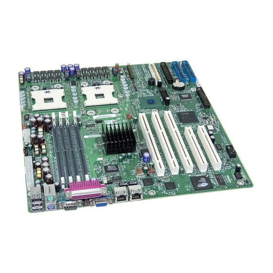
Figure 2. Server Board Connector and Component Locations ✏ NOTE DIMMs 1A and 1B are closest to the side of the board and DIMMs 2A and 2B are in the middle of the board. Intel Server Board SE7500CW2 Product Guide... -
Page 11: Processor
Boxed Processor Fan Heat sink A processor wind tunnel is supplied with the boxed Intel Xeon processor. After the processor and heat sink are installed, install and connect the processor wind tunnel. For proper processor cooling, the fan inlet air temperature should be below 45 °C. -
Page 12: Intel ® E7500 Chipset
Intel E7500 Chipset The Server Board SE7500CW2 includes an Intel E7500 chipset (MCH, ICH3, P64H2) that provides an integrated I/O bridge and memory controller and a flexible I/O subsystem core (PCI). The MCH North Bridge in the E7500 chipset integrates three main functions: •... -
Page 13: Super I/O
PS/2 mouse, and PS/2 keyboard. Serial Ports The Server Board SE7500CW2 provides one DB9 connector on the back panel for serial port 1. Serial port 1 is compatible with 16550A and 16450 modes. The port can be set to one of four different COM-x ports, and each can be enabled separately. -
Page 14: Memory
Memory The Server Board SE7500CW2 contains four 184-pin DIMM sockets and provides up to 4 GB of memory. Memory is partitioned as two banks of DDR DIMMs, each of which provides 144 bits of two-way interleaved memory. The Server Board SE7500CW2 supports up to four ECC DDR DIMMs that are compliant with the JEDEC DDR 200/266 specification. - Page 15 64-bit / 133 MHz PCI-X Capable Subsystem The 64-bit/133 MHz PCI segment includes one 3.3 V keyed PCI expansion slot that can support PCI-X add-in cards up to 133 MHz and are backward compatible to 64 bit/66 MHz, 64 bit/33 MHz, and 32 bit/33 MHz PCI cards.
-
Page 16: Video Controller
Parity enabled Video Controller The Server Board SE7500CW2 includes an ATI Rage XL video controller, 8 MB video SDRAM, and support circuitry for an embedded SVGA video subsystem. The SVGA subsystem supports a variety of modes: up to 1600 x 1200 resolution for CRT displays and up to 1024 x 768 resolution for TFT displays, and up to 16.7 million colors. -
Page 17: Acpi
ACPI requires an operating system that supports this feature. The Server Board SE7500CW2 supports sleep states S0, S4, and S5. When the server board is operating in ACPI mode, the operating system retains control of the system and the operating system policy determines the entry methods and wake-up sources for each sleep state. -
Page 18: Security
Security The Server Board SE7500CW2 BIOS provides the ability to secure itself. Table 2 summarizes the security options available in the BIOS. Table 2. Security Operation Summary Entry Method/ Entry Mode Event Criteria Behavior Exit Criteria After Exit User Power On/Reset... - Page 19 “clear” position clears both passwords. The password clear jumper must be restored to its original position before a new password(s) can be set. The password clear jumper is located on jumper block J106 pins [3-4] on the Server Board SE7500CW2. Description...
- Page 20 Intel Server Board SE7500CW2 Product Guide...
-
Page 21: Configuration Software And Utilities
2 Configuration Software and Utilities This chapter describes the Power-On Self-Test (POST) and server configuration utilities. Table 3 below briefly describes the utilities. Table 3. Configuration Utilities Utility Description and brief procedure Page BIOS Setup If the system does not have a diskette drive or the drive is disabled or misconfigured, use BIOS Setup to enable it. -
Page 22: Using Bios Setup Utility
The bottom portion of the BIOS Setup screen provides a list of commands that are used for navigating the Setup utility. Table 4 describes the keyboard commands you can use in the BIOS Setup menus. Intel Server Board SE7500CW2 Product Guide... -
Page 23: Keyboard Commands
Table 4. Keyboard Commands Press Description <F1> Help - Pressing F1 on any menu invokes the general Help window. ← → The left and right arrow keys are used to move between the major menu pages. The keys have no affect if a submenu or pick list is displayed. ↑... -
Page 24: Menu Selection Bar
ACPI power supply processor, changes to components available and security reboot and controls memory, Setup through the features disable power peripherals, program chipset button and BIOS options Intel Server Board SE7500CW2 Product Guide... -
Page 25: Main Menu
Main Menu To access this menu, select Main on the menu bar at the top of the screen. Advanced Security Power Boot System Exit Main Primary Master Primary Slave Secondary Master Secondary Slave Table 7 lists the options available on the Main menu. This menu allocates resources for hardware components. -
Page 26: Primary/Secondary, Master/Slave Submenu
Selects the method of moving data to and from the hard drive. Automatically set to Standard, which selects the optimum transfer mode. • Disabled Ultra DMA Mode Enables Ultra DMA mode. • Enabled (default) Intel Server Board SE7500CW2 Product Guide... -
Page 27: Advanced Menu
Advanced Menu To access this menu, select Advanced on the menu bar at the top of the screen. Main Security Power Boot System Exit Advanced I/O Device Configuration On Board Device PCI Configuration Server Menu Console Redirection Event Logging Hardware Monitor Table 9 list the selections available on the Advanced menu. - Page 28 Enables support for onboard PXE. (default) • NIC2 • NIC1 • Disabled Hyper-Threading Allows Intel Xeon processors to run in hyperthreading mode. Enabling this setting will improve throughput • Enabled significantly on certain applications. (default) Intel Server Board SE7500CW2 Product Guide...
-
Page 29: I/O Device Configuration Submenu
I/O Device Configuration Submenu To access this submenu, select Advanced on the menu bar at the top of the screen and then I/O Device Configuration. Main Security Power Boot System Exit Advanced I/O Device Configuration On Board Device PCI Configuration Server Menu Console Redirection Event Logging... - Page 30 Sets the DMA channel for the parallel port. (This feature is present • DMA 3 only when Parallel Port is (default) set to Enabled) • Disabled Floppy disk controller Enables or disables the onboard diskette controller. • Enabled (default) Intel Server Board SE7500CW2 Product Guide...
-
Page 31: On Board Device Submenu
Enables the onboard PCI Promise PDC20267 controller. • Enabled (default) • Disabled Onboard NIC 1 Enables the onboard PCI Intel 82550PM Controller (Device 5). • Enabled (default) • Disabled Onboard NIC 2 Enables the onboard PCI Intel 82550PM Controller (Device 4). -
Page 32: Pci Configuration Submenu
Configures the specific PCI device expansion ROM. display submenu Select to PCI Device, Slot #4 Configures the specific PCI device expansion ROM. display submenu PCI Device, Slot #5 Select to Configures the specific PCI device expansion ROM. display submenu Intel Server Board SE7500CW2 Product Guide... -
Page 33: Option Rom Scan Submenu
Table 13 lists the options available on the Option ROM Scan submenu. This submenu appears for each of the options available on the Advanced PCI Configuration submenu above (see Table 12). For brevity, only one example is shown. Table 13. Option ROM Scan Submenu Feature Choices... -
Page 34: Console Redirection Submenu
Indicates whether the console is connected directly to the (default) system or whether a modem is used. • Via modem • Off Continue C.R. after Enables console redirection (C.R.) after the operating system (default) POST has been loaded. • On Intel Server Board SE7500CW2 Product Guide... -
Page 35: Event Logging Submenu
Event Logging Submenu To access this submenu, select Advanced on the menu bar at the top of the screen and then Event Logging. Main Security Power Boot System Exit Advanced I/O Device Configuration On Board Device PCI Configuration Server Menu Console Redirection Event Logging Hardware Monitor... -
Page 36: Hardware Monitor Submenu
4560 RPM System FAN 3 speed No options 4560 RPM System FAN 4 speed No options 4560 RPM CPU FAN 1 speed No options 4560 RPM CPU FAN 2 speed No options 4560 RPM Intel Server Board SE7500CW2 Product Guide... -
Page 37: Security Menu
Security Menu To access this menu, select Security on the menu bar at the top of the screen. Main Advanced Power Boot System Exit Security Table 18 lists the options available on the Security menu. Enabling the Supervisor Password field requires a password for entering Setup. -
Page 38: Power Menu
<Shift+1> enables or disables devices. • <+> and <-> moves the device up or down. • <n> may move the removable device between the hard drive or removable disk. • <d> removes a device that is not installed. Intel Server Board SE7500CW2 Product Guide... -
Page 39: Boot Menu
Table 20. Boot Menu Boot Priority Device Description • Removable Boot Device Specifies the boot sequence according to the device type. The Devices computer will attempt to boot from up to four devices as Boot Device • Hard Drive specified here. Only one of the devices can be an IDE hard Boot Device disk drive. -
Page 40: System Menu
• System Memory: 640 KB • Extended Memory: 1023 MB (BIOS based memory) • Shadow RAM: 384 KB • Cache RAM: 512 KB • Installed Size—DIMM 1A, 1B, 2A, and 2B: DIMM size in MB continued Intel Server Board SE7500CW2 Product Guide... -
Page 41: Exit Menu
Table 21. System Menu (continued) Feature Choices Description Peripherals Provides the port connectors for onboard designators. None of <Enter> these can be modified in user mode Port On Board Port On Board Connector Designator Connector Designator COM 1 ATA100 Secondary IDE COM 2 J101 LPT 1... -
Page 42: Upgrading The Bios
You can upgrade to a new version of the BIOS using the new BIOS files and the BIOS upgrade utility, PHLASH.EXE. You can obtain the BIOS upgrade file and the PHLASH.EXE utility through your computer supplier or from the Intel Customer Support Web site: http://support.intel.com/support/motherboards/server/SE7500CW2 ✏... -
Page 43: Upgrading The Bios
Creating the BIOS Upgrade Diskette The BIOS upgrade file is a compressed self-extracting archive that contains the files you need to upgrade the BIOS. 1. Insert the bootable diskette into the diskette drive. 2. Extract the contents of the BIOS.EXE file onto the bootable diskette. To do so, simply type the file name (with or without the extension) at the a:\ prompt, for example “BIOS.EXE.”... -
Page 44: Changing The Bios Language
1. Obtain the BIOS update file package from http://support.intel.com. 2. A file called “crisis.zip” is one of the files included with each Server Board SE7500CW2 BIOS release file package. Unzip the “crisis.zip” file to a directory on your hard drive. -
Page 45: Hardware Monitoring
Monitors chassis ambient temperature Intel LDCM software and a white paper that provides more information on using Intel LDCM software are available on the Intel Server Board SE7500CW2 Resource CD and are also available for download at the following Web site: http://www.support.intel.com/support/motherboards/server/SE7500CW2... - Page 46 Intel Server Board SE7500CW2 Product Guide...
-
Page 47: Server Board Installation
To ensure EMC compliance with your local regional rules and regulations, the final configuration of your end system product may require additional EMC compliance testing. For more information please contact your local Intel Representative. See “Regulatory and Integration Information” on page 87 for product Safety and EMC regulatory compliance information. -
Page 48: Safety And Regulatory Compliance
(or higher) and operating at the same (or higher) speed as the microprocessor used on this server board. Server board diagram label provided: Place the label inside the chassis in an easy-to-see location, preferably oriented similarly to the server board. Intel Server Board SE7500CW2 Product Guide... -
Page 49: Minimum Hardware Requirements
To avoid integration difficulties and possible board damage, your system must meet the following minimum requirements. For a list of qualified memory and chassis components see: http://support.intel.com/support/motherboards/server/SE7500CW2 Processor Minimum of one 1.8 GHz Intel Xeon processor with 512K cache support. For a complete list of supported processors, see: http://support.intel.com/support/motherboards/server/SE7500CW2 Memory Minimum of two 128 MB Registered, ECC, DDR 200/266 compliant, 184-pin DIMMs. -
Page 50: Installation Procedures
Attaching the Gasket to the I/O Shield 1. Remove the two backing strips from the gasket. 2. Press the gasket onto the inside face of the I/O shield as shown. OM14074 Figure 3. Attaching the Gasket to the I/O Shield Intel Server Board SE7500CW2 Product Guide... -
Page 51: Attaching The Label To The I/O Shield
Attaching the Label to the I/O Shield 1. Remove the backing from the label included with your server board. 2. Press the label onto the outside face of the I/O shield. See Figure 4, A. OM14360 Figure 4. Attaching the Label to the I/O Shield Installing the I/O Shield 1. -
Page 52: Configuring Chassis Standoffs
1. Chassis comes with positions 1, 4, 6, 20, 23, and 26 preinstalled. 2. Install standoffs in the remaining positions (7, 18, 19, P, and S). Standoffs are included with your chassis. OM14221 Figure 6. Configuring Chassis Standoffs Intel Server Board SE7500CW2 Product Guide... -
Page 53: Installing Rubber Bumpers
Installing Rubber Bumpers For the Server Chassis SC5200: 1. Measure and mark the bumper placement locations in your chassis by placing your ruler against the standoffs as shown below. 2. Remove the backing from the bumpers and press firmly into position. Rubber bumpers are included with your chassis. -
Page 54: Installing The Server Board
Using the screws that came with your chassis, mount the board to the chassis. Main Power Aux. Pwr DIMM Memory Connector 3B DIMM Memory Connector 3A DIMM Memory Connector 2B DIMM Memory Connector 2A OM14423 Figure 9. Attaching the Server Board Intel Server Board SE7500CW2 Product Guide... -
Page 55: Installing Memory
DIMMs must be installed in pairs. The furthest DIMM pair from the MCH must be populated first. No DIMM mixing is allowed within a bank. Between banks only the DIMM size may be different. All DIMMs must be the same speed and architecture. For a list of supported memory, visit the Intel Support Web site: http://support.intel.com/support/motherboards/server/SE7500CW2... -
Page 56: Installing The Processor(S)
3. Remove the chassis cover (see your system or chassis documentation for instructions). 4. When installing a processor, insert the retention brackets and tighten the four retention screws. OM14471 Figure 11. Installing the Retention Brackets Intel Server Board SE7500CW2 Product Guide... -
Page 57: Opening Socket Lever And Attaching Processor
Attaching the Processor ✏ NOTE This server board has “zero-insertion-force” sockets. If the processor does not drop easily into the socket holes, make sure the lever is in the full upright position and the processor is oriented properly. 1. Lift the socket lever on the processor. OM14473 Figure 12. -
Page 58: Installing The Processor Wind Tunnel
Attaching the Processor Wind Tunnel Assembly Install the processor wind tunnel center section over the heat sink (Figure 15). Note that the plastic tabs engage the tabs on the retention clips. OM14475 Figure 15. Attaching the Wind Tunnel Assembly Intel Server Board SE7500CW2 Product Guide... -
Page 59: Attaching The Heat Sink Fan
Attaching the Heat Sink Fan Attach the fan to the wind tunnel air intake section as shown in Figure 16. The fan label (Figure 16, A) must point into the air intake section. OM14476 Figure 16. Attaching the Heat Sink Fan Attaching Intake and Exhaust Assemblies ✏... -
Page 60: Installing The Optional Scsi Add-In Card
Installing the Optional SCSI Add-in Card Certain versions of the Server Board SE7500CW2 ship with an Ultra160 SCSI card. This card has the following features: • † Ultra160 single channel based on the LSI 53C1000 SCSI controller • PCI 2.2 compliant •... -
Page 61: Making Connections To The Server Board
Making Connections to the Server Board OM14422A Main power ATA 100 RAID IDE Auxiliary signal Floppy C. +12 V CPU power Front panel USB D. CPU fan 1 Chassis intrusion CPU fan 2 M. I2C Front chassis fans N. Rear chassis fans G. -
Page 62: Cable Routing
1. Remove the top half of the EPAC. 2. Route cables as shown in Figure 19. 3. Replace the top half of the EPAC. OM14196 Ribbon Cable(s) Lower Device Bay Figure 19. Routing IDE Cables Intel Server Board SE7500CW2 Product Guide... -
Page 63: Routing The Floppy Drive Cable
Floppy Drive Cable Route the floppy drive cable as shown in Figure 20, A. OM14421 Figure 20. Routing the Floppy Drive Cable Server Board Installation... -
Page 64: Finishing Up
4. Connect the power cable to the back panel and to an AC outlet. OM14424 AC Power Keyboard USB 1, 2, and 3 G. Serial port 1 C. Mouse H. Video D. Parallel port Network Serial port 2 Figure 21. Making Back Panel Connections Intel Server Board SE7500CW2 Product Guide... -
Page 65: Upgrading
4 Upgrading Tools and Supplies Needed • Phillips (cross head) screwdriver (#1 bit and #2 bit) • Jumper removal tool or needle nosed pliers • Pen or pencil • Antistatic wrist strap and conductive foam pad (recommended) Cautions These warnings and cautions apply throughout this chapter. Only a technically qualified person should configure the server board. -
Page 66: Memory
DIMMs must be installed in pairs. The furthest DIMM pair from the MCH must be populated first. No DIMM mixing is allowed within a bank. Between banks only the DIMM size may be different. All DIMMs must be the same speed and architecture. For a list of supported memory, visit the Intel Support Web site at: http://support.intel.com/support/motherboards/server/SE7500CW2... -
Page 67: Processors
Make sure your server can handle a newer, faster processor (thermal and power considerations). For exact information about processor interchangeability, contact your customer service representative or visit the Intel Customer Support Web site: http://support.intel.com/support/motherboards/server/SE7500CW2... -
Page 68: Adding Or Replacing A Processor
3. Remove the chassis cover (see your system or chassis documentation for instructions). 4. When installing a processor, insert the retention brackets and tighten the four retention screws. OM14471 Figure 23. Installing the Retention Brackets Intel Server Board SE7500CW2 Product Guide... -
Page 69: Opening Socket Lever And Attaching Processor
Attaching the Processor ✏ NOTE This server board has “zero-insertion-force” sockets. If the processor does not drop easily into the socket holes, make sure the lever is in the full upright position and the processor is oriented properly. 1. Lift the socket lever on the processor. OM14473 Figure 24. -
Page 70: Installing The Processor Wind Tunnel
Attaching the Processor Wind Tunnel Assembly Install the processor wind tunnel center section over the heat sink (Figure 27). Note that the plastic tabs engage the tabs on the retention clips. OM14475 Figure 27. Attaching the Wind Tunnel Assembly Intel Server Board SE7500CW2 Product Guide... -
Page 71: Attaching The Heat Sink Fan
Attaching the Heat Sink Fan Attach the fan to the wind tunnel air intake section as shown in Figure 28. The fan label (Figure 28, A) must point into the air intake section. OM14476 Figure 28. Attaching the Heat Sink Fan Attaching Intake and Exhaust Assemblies ✏... -
Page 72: Removing A Processor
Levér det brugte batteri tilbage til leverandøren. ADVARSEL Lithiumbatteri - Eksplosjonsfare. Ved utskifting benyttes kun batteri som anbefalt av apparatfabrikanten. Brukt batteri returneres apparatleverandøren. Intel Server Board SE7500CW2 Product Guide... -
Page 73: Replacing The Backup Battery
VARNING Explosionsfara vid felaktigt batteribyte. Använd samma batterityp eller en ekvivalent typ som rekommenderas av apparattillverkaren. Kassera använt batteri enligt fabrikantens instruktion. VAROITUS Paristo voi räjähtää, jos se on virheellisesti asennettu. Vaihda paristo ainoastaan laitevalmistajan suosittelemaan tyyppiin. Hävitä käytetty paristo valmistajan ohjeiden mukaisesti. 1. - Page 74 Intel Server Board SE7500CW2 Product Guide...
-
Page 75: Solving Problems
NEMA 5-15R outlet for 100-120 V∼ or a NEMA 6-15R outlet for 200-240 V∼? q Are all integrated components from the tested components lists? Check the tested memory, and chassis lists, as well as the supported hardware and operating system list on the Intel Customer Support Web site. -
Page 76: Running New Application Software
If you suspect that a transient voltage spike, power outage, or brownout might have occurred, reload the software and try running it again. (Symptoms of voltage spikes include a flickering video display, unexpected system reboots, and the system not responding to user commands.) Intel Server Board SE7500CW2 Product Guide... -
Page 77: More Problem Solving Procedures
✏ NOTE Random errors in data files: If you are getting random errors in your data files, they may be getting corrupted by voltage spikes on your power line. If you are experiencing any of the above symptoms that might indicate voltage spikes on the power line, you may want to install a surge suppressor between the power outlet and the system power cord. -
Page 78: Verifying Proper Operation Of Key System Lights
Are there other problems with the system? If so, check the items listed under ‘System Cooling Fans Do Not Rotate Properly.” If all items are correct and problems persist, contact your service representative or authorized dealer for help. Intel Server Board SE7500CW2 Product Guide... -
Page 79: No Characters Appear On Screen
No Characters Appear on Screen Check the following: q Is the keyboard functioning? Check to see that the “Num Lock” light is functioning. q Is the video monitor plugged in and turned on? q Are the brightness and contrast controls on the video monitor properly adjusted? q Are the video monitor switch settings correct? q Is the video monitor signal cable properly installed? q Is the onboard video controller enabled? -
Page 80: System Cooling Fans Do Not Rotate Properly
“Onboard Floppy” is set to “Disabled.” If the problem persists, there may be a problem with the diskette drive, server board, or drive signal cable. Contact your service representative or authorized dealer for help. Intel Server Board SE7500CW2 Product Guide... -
Page 81: Hard Disk Drive Activity Light Does Not Light
Hard Disk Drive Activity Light Does Not Light The hard disk drive activity light is not connected to the Server Board SE7500CW2 front panel. CD-ROM Drive Activity Light Does Not Light Check the following: q Are the CD-ROM drive’s power and signal cables properly installed? -
Page 82: Pci Installation Tips
If the problem persists, contact the software vendor’s customer service representative for help. Bootable CD-ROM Is Not Detected Check the following: q Is the BIOS configured to allow the CD-ROM to be the first bootable device? Intel Server Board SE7500CW2 Product Guide... -
Page 83: Getting Help
Telephone All calls are billed US $25.00 per incident, levied in local currency at the applicable credit card exchange rate plus applicable taxes. (Intel reserves the right to change the pricing for telephone support at any time without notice). In U.S. and Canada... - Page 84 Intel Server Board SE7500CW2 Product Guide...
-
Page 85: Technical Reference
7 Technical Reference Configuration Jumpers Main Power J106 OM14430 Figure 31. Configuration Jumper Location Table 24. Configuration Jumper (J106) Jumper Name Pins What happens at system reset BIOS Recovery If these pins are jumpered, the system will attempt BIOS recovery. These pins should not be jumpered for normal operation. -
Page 86: Front Panel Header
7 & 9 LED show hard disk drive activity 1 & 5 LED shows power on 22 & 24 LED shows network interface controller activity 12 & 14 LED shows network interface controller activity Intel Server Board SE7500CW2 Product Guide... -
Page 87: Regulatory And Integration Information
EMKO-TSE (74-SEC) 207/94 (Nordics) • GOST R 50377-92 (Russia) Product EMC Compliance The Server Board SE7500CW2 has been has been tested and verified to comply with the following ® electromagnetic compatibility (EMC) regulations when installed a compatible Intel host system. -
Page 88: Product Regulatory Compliance Markings
(1) this device may not cause harmful interference, and (2) this device must accept any interference received, including interference that may cause undesired operation. For questions related to the EMC performance of this product, contact: Intel Corporation 5200 N.E. Elam Young Parkway Hillsboro, OR 97124 1-800-628-8686 Intel Server Board SE7500CW2 Product Guide... -
Page 89: Industry Canada (Ices-003)
This equipment has been tested and found to comply with the limits for a Class A digital device, pursuant to Part 15 of the FCC Rules. These limits are designed to provide reasonable protection against harmful interference in a residential installation. This equipment generates, uses, and can radiate radio frequency energy and, if not installed and used in accordance with the instructions, may cause harmful interference to radio communications. -
Page 90: Korean Rrl Compliance
This product has been tested and complies with MIC Notices No. 1997-41 and 1997-42. The product has been marked with the MIC logo to illustrate compliance. The English translation for the above is as follows: 1. Type of Equipment (Model Name): SE7500CW2 2. Certification No.: Contact Intel Representative 3. Name of Certification Recipient: Intel 4. -
Page 91: Index
CMOS, 45 IDE interface, 12 clear to reconfigure diskette drive, 22 CNB20HE-SL, 12 IMB bus, 12 Configuration, 17, 23 Intel 82559, 7, 16 configuring server board jumpers, location on Interrupt, 12 server board, 85 JEDEC, 14 configuring system, Setup, 21... - Page 92 77 components may be hot, 67 screen characters incorrect, 79 dispose of lithium battery safely, 72 system cooling fans do not rotate, 80 ESD can damage product, 47, 65 Intel Server Board SE7500CW2 Product Guide...
Need help?
Do you have a question about the SE7500CW2 and is the answer not in the manual?
Questions and answers