Intel SE7520JR2 - Server Board Motherboard User Manual
User guide
Hide thumbs
Also See for SE7520JR2 - Server Board Motherboard:
- Technical manual (225 pages) ,
- Technical specifications update (22 pages) ,
- Tested hardware and operating system list (30 pages)
Table of Contents
Advertisement
Quick Links
Advertisement
Table of Contents

Related Manuals for Intel SE7520JR2 - Server Board Motherboard


Summary of Contents for Intel SE7520JR2 - Server Board Motherboard
- Page 1 Intel® Server Board SE7520JR2 User Guide Order Number: C51508-001...
- Page 2 Intel’s own chassis are designed and tested to meet the intended thermal requirements of these components when the fully integrated system is used together. It is the responsibility of the system integrator that chooses not to use Intel developed server building blocks to consult vendor datasheets and operating parameters to determine the amount of airflow required for their specific application and environmental conditions.
-
Page 3: About This Manual
This document provides a brief overview of the features of the board/chassis, a list of accessories or other components you may need, troubleshooting information, and instructions on how to add and replace components on the Intel Server Board SE7520JR2. For the latest version of this manual, refer to http://support.intel.com/support/motherboards/server/SE7520JR2/. -
Page 4: Additional Information And Software
Driver (for an extensive list of drivers available) Operating System Driver (for operating system drivers) For firmware and BIOS updates, or Firmware Updates BIOS recovery For diagnostics test software Diagnostics See also the Intel® Server Deployment Toolkit CD that came with your server board... -
Page 5: Safety Information
To ensure EMC compliance with your local regional rules and regulations, the final configuration of your end system product may require additional EMC compliance testing. For more information please contact your local Intel Representative. “Regulatory and Integration Information” for product safety compliance and EMC regulatory compliance information. - Page 6 Preface Warnings System power on/off: The power button DOES NOT turn off the system AC power. To remove power from system, you must unplug the AC power cord from the wall outlet. Make sure the AC power cord is unplugged before you open the chassis, add, or remove any components.
-
Page 7: Safety Cautions
Safety Cautions Read all caution and safety statements in this document before performing any of the instructions. See also Intel Server Boards and Server Chassis Safety Information on the Resource CD and/or at http://support.intel.com/support/motherboards/server/sb/cs-010770.htm. SAFETY STEPS: Whenever you remove the chassis covers to access the inside of the system, follow these steps: Turn off all peripheral devices connected to the system. - Page 8 Lisez attention toutes les consignes de sécurité et les mises en garde indiquées dans ce document avant de suivre toute instruction. Consultez Intel Server Boards and Server Chassis Safety Information sur le CD Resource CD ou bien rendez-vous sur le site http://support.intel.com/support/motherboards/server/sb/cs-010770.htm.
- Page 9 Instrucciones de seguridad importantes Lea todas las declaraciones de seguridad y precaución de este documento antes de realizar cualquiera de las instrucciones. Vea Intel Server Boards and Server Chassis Safety Information en el CD Resource y/o en http://support.intel.com/support/motherboards/server/sb/cs-010770.htm. INSTRUCCIONES DE SEGURIDAD: Cuando extraiga la tapa del chasis para acceder al interior del sistema, siga las siguientes instrucciones: Apague todos los dispositivos periféricos conectados al sistema.
- Page 10 Preface...
-
Page 11: Table Of Contents
Memory ........................21 Optional Hardware ........................ 24 Hard Disk Drives ......................24 Intel® Management Module ..................24 Intel® Local Control Panel ................... 24 2 Hardware Installations and Upgrades ............25 Before You Begin ........................25 Tools and Supplies Needed ....................25 Installing and Removing Memory.................. - Page 12 Product Regulatory Compliance Markings ..............52 Electromagnetic Compatibility Notices.................. 53 FCC (USA) ........................53 Industry Canada (ICES-003) ..................54 Europe (CE Declaration of Conformity)................ 54 Taiwan Declaration of Conformity (BSMI) ..............54 Korean Compliance (RRL) ................... 54 ® Intel Server Issue Report Form............... 59...
- Page 13 Contents Figures Figure 1. Intel ® Server Board SE7520JR2 ................15 Figure 2. Server Board Connector and Component Locations ..........18 Figure 3. Configuration Jumper Location................... 19 Figure 4. Back Panel Connectors ....................20 Figure 5. Installing Memory......................26 Figure 6. Opening Socket Lever ....................28 Figure 7.
- Page 14 Contents...
-
Page 15: Server Board Features
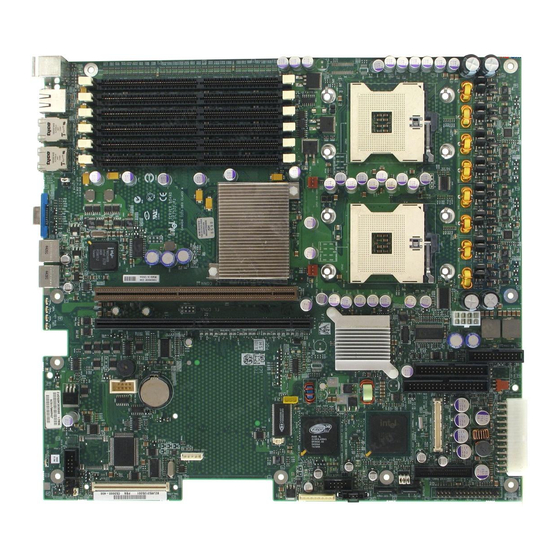
1 Server Board Features ® This chapter briefly describes the main features of the Intel Server Board SE7520JR2. This chapter provides a photograph of the product, a list of the server board features, and diagrams showing the location of important components and connections on the server board. -
Page 16: Server Board Features
Server Board Features Feature Description Processors Support for up to two Intel® Xeon™ processors with an 800 MT/s MHz front side bus and frequencies starting at 2.8 GHz. Memory Memory mirroring and memory sparing options Six DIMM slots supporting DDR-2 400MHz memory (SE7520JR2SCSID2 and... - Page 17 Floppy Drive Single Floppy channel accessed through either of two connectors. When integrated with either the SATA or SCSI backplanes in the Intel Server Chassis SR1400 or SR2400, the floppy controller signals are routed through the 100-pin flex cable. Other server configurations can use the legacy 24-pin connector.
-
Page 18: Connector And Header Locations
H DIMM sockets 24-pin SSI power connector DD ICMB connector Processor 1 fan header 50-pin control panel connector 120-pin connector for optional Intel® Management Module Processor socket 1 34-pin SSI control panel connector K Processor socket 2 SATA port 1... -
Page 19: Configuration Jumpers
These pins should be jumpered for normal system operation. “C” in figure If these pins are jumpered, the CMOS settings will be cleared on the next reset. above) These pins should not be jumpered for normal operation. Intel® Server Board SE7520JR2 User Guide... -
Page 20: Back Panel Connectors
Server Board Features Back Panel Connectors TP00762 A PS/2 Mouse Video B PS/2 Keyboard USB port 1 C Serial Port B USB port 2 D NIC port 1 (1 Gb) SCSI channel B NIC port 2 (1 Gb) Figure 4. Back Panel Connectors The NIC LEDs at the right and left of each NIC provide the following information. -
Page 21: Hardware Requirements
Software.” Processor One or two Intel® Xeon™ processors with an 800MHz front side bus and a minimum of 2.8 GHz frequency must be installed. The following table outlines the supported processors. For a complete list of supported processors, see the links under “Additional Information and... -
Page 22: Dimm Module Memory Capacity Support
Information and Software.” Memory Sparing and Mirroring The Intel® E7520 chipset includes hardware that supports memory mirroring and memory on-line sparing. Both memory mirroring and memory on-line sparing provide a way to prevent data loss in case a DIMM fails. -
Page 23: Power Supply
Power Supply A minimum of 500 Watts is required. Your supply must provide a minimum of 1.2 A of 5 V standby current or the board will not boot. Intel® Server Board SE7520JR2 User Guide... -
Page 24: Optional Hardware
See the documentation included with your server chassis for additional drive information and drive installation instructions. Intel® Management Module Two versions of the Intel® Management Module are available to provide enhanced server management features. The Intel Management Module - Professional Edition: contains a hardware mezzanine card that plugs into the server board. -
Page 25: Hardware Installations And Upgrades
1. Observe the safety and ESD precautions at the beginning of this book. 2. Turn off all peripheral devices connected to the server. Turn off the server. 3. Disconnect the AC power cord from the server. Intel® Server Board SE7520JR2 User Guide... -
Page 26: Figure 5. Installing Memory
Hardware Installations and Upgrades 4. Remove the server’s cover. See the documentation that accompanied your server chassis for instructions on removing the server’s cover. 5. Locate the DIMM sockets (see Figure 5). DIMM 2A DIMM 2B DIMM 3B DIMM 1A DIMM 3A DIMM 1B TP00761... -
Page 27: Removing Dimms
7. Reinstall and reconnect any parts you removed or disconnected to reach the DIMM sockets. 8. Replace the server’s cover and reconnect the AC power cord. See the documentation that accompanied your server chassis for instructions on installing the server’s cover. Intel® Server Board SE7520JR2 User Guide... -
Page 28: Installing Or Replacing The Processor
Hardware Installations and Upgrades Installing or Replacing the Processor CAUTIONS Processor must be appropriate: You may damage the server board if you install a processor that is inappropriate for your server. See “Additional Information and Software” for a link to the list of compatible processor(s). ESD and handling processors: Reduce the risk of electrostatic discharge (ESD) damage to the processor by doing the following: (1) Touch the metal chassis before touching the processor or server board. -
Page 29: Figure 7. Inserting Processor
6. Align the pins of the processor with the socket, and insert the processor into the socket. ✏ NOTE Make sure the alignment triangle mark and the alignment triangle cutout align correctly. TP00764 Figure 7. Inserting Processor 7. Lower the socket lever completely. TP00765 Figure 8. Closing Socket Lever Intel® Server Board SE7520JR2 User Guide... -
Page 30: Removing A Processor
Hardware Installations and Upgrades Installing the Heat Sink(s) 1. The heat sink has Thermal Interface Material (TIM) located on the bottom of it. Use caution when you unpack the heat sink so you do not damage the TIM. 2. Set the heat sink over the processor, lining up the four captive screws with the four posts surrounding the processor. -
Page 31: Rj45 Serial Port Configuration
6. Move the jumper from the default position covering pins 1 and 3 to cover pins 2 and 4. J7A1 1-3: DCD to DTR (Default) 2-4: DSR to DTR TP00772 Figure 10. Changing the Serial Port Configuration Intel® Server Board SE7520JR2 User Guide... -
Page 32: Replacing The Backup Battery
Hardware Installations and Upgrades Replacing the Backup Battery The lithium battery on the server board powers the RTC for up to 10 years in the absence of power. When the battery starts to weaken, it loses voltage, and the server settings stored in CMOS RAM in the RTC (for example, the date and time) may be wrong. -
Page 33: Figure 11. Replacing The Backup Battery
8. Remove the new lithium battery from its package, and, being careful to observe the correct polarity, insert it in the battery socket. 9. Close the chassis. 10. Run Setup to restore the configuration settings to the RTC. Intel® Server Board SE7520JR2 User Guide... -
Page 34: Server Utilities
These parameters can be changed if the user has adequate security rights. If a value cannot be changed for any reason, the feature’s value field is inaccessible. Table 6 describes the keyboard commands you can use in the BIOS Setup menus. Intel® Server Board SE7520JR2 User Guide... -
Page 35: Table 6. Keyboard Commands
If “Yes” is selected and the Enter key is pressed, all changes are saved and Setup is exited. If “No” is selected and the Enter key is pressed, or the ESC key is pressed, the user is returned to where they were before F10 was pressed without affecting any existing values. Intel® Server Board SE7520JR2 User Guide... -
Page 36: Upgrading The Bios
Server Utilities Upgrading the BIOS The upgrade utility allows you to upgrade the BIOS in flash memory. The code and data in the upgrade file include the following: On-board system BIOS, including the recovery code, BIOS Setup Utility, and strings. On-board video BIOS, SCSI BIOS, and other option ROMs for devices embedded on the server board. -
Page 37: Upgrading The Bios
3. Move the jumper from the normal operation position, Password Clear Protect, at pins 1 and 2 to the Password Clear Erase position, covering pins 2 and 3 as indicated in the following diagram. TP01240 Figure 12. Password Recovery Jumper Intel® Server Board SE7520JR2 User Guide... -
Page 38: Clearing The Cmos
Server Utilities 4. Reconnect the AC power, power up the system. 5. Power down the system and disconnect the AC power. 6. Return the Password Clear jumper to the Password Clear Protect position, covering pins 1 and 2. 7. Close the server chassis. 8. -
Page 39: Troubleshooting
SCSI drivers. Intel provides a package called the “Platform Confidence Test” that may help with your diagnostics. See “Additional Information and... -
Page 40: Problems Following Initial System Installation
Troubleshooting Problems following Initial System Installation Problems that occur at initial system startup are usually caused by an incorrect installation or configuration. Hardware failure is a less frequent cause. If the problem you are experiencing is with a specific software application, see “Problems with Newly Installed Application Software.”... -
Page 41: Hardware Diagnostic Testing
Once the system boots up, the operating system prompt appears on the screen. The prompt varies according to the operating system. If the operating system prompt does not appear, see “No Characters Appear on Screen” Intel® Server Board SE7520JR2 User Guide... -
Page 42: Specific Problems And Corrective Actions
Troubleshooting Specific Problems and Corrective Actions This section provides possible solutions for these specific problems: Power light does not light. No characters appear on screen. Characters on the screen appear distorted or incorrect. System cooling fans do not rotate. Diskette drive activity light does not light. Hard disk drive activity light does not light. -
Page 43: No Characters Appear On Screen
Are the brightness and contrast controls properly adjusted on the video monitor? See the manufacturer’s documentation. Are the video monitor’s signal and power cables properly installed? Does this video monitor work correctly if plugged into a different system? Intel® Server Board SE7520JR2 User Guide... -
Page 44: System Cooling Fans Do Not Rotate Properly
Troubleshooting System Cooling Fans Do Not Rotate Properly If the system cooling fans are not operating properly, it is an indication of possible system component failure. Check the following: Is the power-on light lit? If not, see “Power Light Does Not Light”... -
Page 45: Cd-Rom Drive Or Dvd-Rom Drive Activity Light Does Not Light
Make sure your BIOS is current. See “Additional Information and Software” for a link to the current version. Make sure the other adapter supports shared interrupts. Make sure your operating system supports shared interrupts. Try reseating the add-in adapter. Intel® Server Board SE7520JR2 User Guide... -
Page 46: System Boots When Installing Pci Card
Troubleshooting The add-in adapter stopped working without apparent cause. Try reseating the adapter first; then try a different slot if necessary. The network driver files may be corrupt or deleted. Delete and then reinstall the drivers. Run the diagnostics. System Boots when Installing PCI Card System Server Management features require full-time “standby”... -
Page 47: Devices Are Not Recognized Under Device Manager (Windows* Operating System)
Devices are not Recognized under Device Manager (Windows* Operating System) The Windows* operating systems do not include all of the drivers for the Intel® chipsets, onboard NICs, and other components. See “Additional Information and Software”... -
Page 48: Led Information
Troubleshooting LED Information ® The Intel Server Board SE7520JR2 includes LEDs that can aid in troubleshooting your system. A table of these LEDs with a description of their use is listed below. LED Name Function Location Color Notes Aid in server... -
Page 49: Bios Post Beep Codes
Replace or reseat the system video add-in card. If on-board video is bing used, the server board may be faulty. In addition to the beep codes above, additional beep codes are provided if an Intel® Management Module is installed. The Intel Management Modules provide the following additional beep codes. - Page 50 Troubleshooting...
-
Page 51: Product Regulatory Compliance
® electromagnetic compatibility (EMC) regulations when installed a compatible Intel host system. For information on compatible host system(s) refer to Intel’s Server Builder Web site or contact your local Intel representative. FCC /ICES-003 - Emissions (USA/Canada) Verification CISPR 22 – Emissions (International) -
Page 52: Certifications / Registrations / Declarations
Regulatory and Compliance Information Certifications / Registrations / Declarations UL Certification (US/Canada) CE Declaration of Conformity (CENELEC Europe) FCC/ICES-003 Class A Attestation (USA/Canada) C-Tick Declaration of Conformity (Australia) MED Declaration of Conformity (New Zealand) BSMI Certification (Taiwan) GOST – Listed on one System License (Russia) Belarus –... -
Page 53: Electromagnetic Compatibility Notices
TV reception. All cables used to connect to peripherals must be shielded and grounded. Operation with cables, connected to peripherals, that are not shielded and grounded may result in interference to radio and TV reception. Intel® Server Board SE7520JR2 User Guide... -
Page 54: Industry Canada (Ices-003)
English translation of the notice above: 1. Type of Equipment (Model Name): On License and Product 2. Certification No.: On RRL certificate. Obtain certificate from local Intel representative 3. Name of Certification Recipient: Intel Corporation 4. Date of Manufacturer: Refer to date code on product... - Page 55 Regulatory and Compliance Information Intel® Server Board SE7520JR2 User Guide...
-
Page 56: Getting Help
Telephone All calls are billed US $25.00 per incident, levied in local currency at the applicable credit card exchange rate plus applicable taxes. (Intel reserves the right to change the pricing for telephone support at any time without notice). Before calling, fill out an “Error! Not a valid bookmark... - Page 57 800 843 4481 Chile (Mainland and Juan) Contact AT&T USA at 800 225 288. Once connected, dial 800 843 4481 Miami 1 800 621 8423 For an updated support contact list, see http://www.intel.com/support/9089.htm/ Intel® Server Board SE7520JR2 User Guide...
-
Page 59: Intel Server Issue Report Form
® Intel Server Issue Report Form NOTE An on-line / automatic submission version of this form is available at http://support.intel.com/support/motherboards/server/SE7520JR2/. For the fastest service, please submit your form via the Internet. Date Submitted: Company Name: Contact Name: Email Address: Intel Server Product: Priority (Critical, Hot, High, Low): Brief Problem Description. - Page 60 DIMM1B Vendor / part number: System BIOS Version: DIMM2A MB: HSC Firmware Version: DIMM2A Vendor / part number: Chassis Model DIMM2B MB: Intel SR1400 DIMM2B Vendor / part number: Intel SR2400 DIMM3A MB Other (Vendor / Model): DIMM3A Vendor / part number DIMM3B MB...
- Page 61 (10/100/1000 Mb) Hard Drive Information: # of drives installed: Make/Model/Firmware Revision SCSI # of drives installed: Hot-swap: Fixed: Make/Model/Firmware Revision SATA # of drives installed: Make/Model/Firmware Revision Hot-swap: Fixed: Intel® Server Board User Guide...
- Page 62 Management Information: On-Board Platform Instrumentation only (Default) Intel® Management Module – Professional Edition Intel® Management Module – Advanced Edition Control Panel Information: Standard Control Panel Intel® Local Control Panel...
- Page 63 In the space below, provide a complete description of the steps used to reproduce the problem or a complete description of where the problem can be found. Please also include any details on troubleshooting already done. Intel® Server Board User Guide...
Need help?
Do you have a question about the SE7520JR2 - Server Board Motherboard and is the answer not in the manual?
Questions and answers