
Related Manuals for Emerson DUNNINGTON CF3100AGW00


Summary of Contents for Emerson DUNNINGTON CF3100AGW00
-
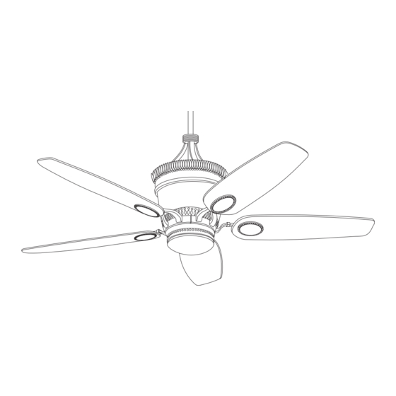
Page 1: Ceiling Fan
READ AND SAVE THESE INSTRUCTIONS DUNNINGTON ™ Ceiling Fan Owner's Manual Model Numbers CF3100AGW00 CF3100BZH00 Aged Walnut Bronze Heritage 26.0 Net Weight: Lbs. Part No. F40BP73610000 Form No. BP7361 U.L. Model No.: CF3100... -
Page 2: Safety Instructions
WARNING: To reduce the risk of fire or electric shock, this fan should only be used with fan speed control SW105, manufactured by Rhine Electric Co., Ltd. WARNING: To avoid fire, shock or injury, do not use an Emerson or any other brand of control not specifically approved for this fan. -
Page 3: Unpacking Instructions
Emerson Electric Co. Substitution of parts or proceeding. accessories not designated for use with this product by Emerson Electric Co. could result in personal injury or property damage. 1. Open styrofoam unit containing fan. Remove upper and center sections of styrofoam unit. Remove parts and check to see that you have received the following: a. -
Page 4: Electrical Requirements
1. Place the flange assembly onto the blade. Place regulate your ceiling fan speed, airflow direction, the flange medallion assembly into the three holes and light intensity. An optional Emerson Electric on the opposite side of the blade. SR110 Remote Control may also be used. - Page 5 7. Connect the 4-pin connector from the decorative 12. Carefully turn over the partially assembled ceiling light kit assembly to the 4-pin connector of the fan and place onto the flat surface of the switch housing (Figure 3). styrofoam. 8. Connect the switch housing blue wire single-pin 13.
- Page 6 Slide 16” Or Optional Longer Downrod Installation: WARNING the decorative scrolls over the 16” downrod to rest upon the decorative upper housing It is critical that the clevis pin in the motor coupling (Figure 9) To secure the decorative scrolls to the is properly installed and the setscrew securely downrod, tighten the Philips head screw in the tightened.
-
Page 7: Your Ceiling Fan How To Hang
WARNING Hanger bracket must seat firmly against outlet box. If the outlet box is recessed, remove wall board until SETSCREW bracket contacts box. If bracket and/or outlet box are not securely attached, the fan could wobble or fall. DOWNROD HANGER BALL OUTLET CEILING COVER Figure 10... -
Page 8: How To Wire Your Ceiling Fan
How to Wire Your Ceiling Fan 3. Using wire connectors (supplied), make wiring If you feel that you do not have enough electrical connections as follows (Figure 14 and 15): wiring knowledge or experience, have your fan installed by a licensed electrician. a. - Page 9 6. Screw the two 1-1/4” threaded studs (supplied) into SW105 RECEIVER the tapped holes in the hanger bracket (Figure 16). 7. Lift the ceiling cover up to the threaded studs and BLACK SUPPLY WIRE turn until studs protrude through the holes in the ceiling cover (Figure 17).
-
Page 10: Light Kit Installation
Switch Cover Installation Light Kit Installation If no light kit is desired, continue with non-light 1. Install the 50-watt (maximum) bi-pin (Type GY8) halogen bulb (supplied) into the light kit socket switch cover installation. (Figure 18). Do not touch the glass bulb; use the NOTE: Do not install the 50-watt (max.) bi-pin porcelain base to screw in the bulb, or wear halogen bulb or unhook the 50-watt (max.) bi-pin... - Page 11 Setting Operating Installation Frequency of Wall Control of Wall Control and Receiver (Figure 21) WARNING Your wall control and receiver have code switches which must be set in one of 16 possible code Turning off wall switch is not sufficient. To avoid combinations.
-
Page 12: Operating Your Ceiling Fan
5. To turn the lights on and off, press and release the Operating Your U/L (uplight) button or the D/L (downlight) button (if Ceiling Fan downlight kit is added to fan). The lights will turn on at the light level previously set (see Step 4). IMPORTANT Red light turns on when any button is pressed. -
Page 13: Maintenance
NOTE: Periodically check the tightness of the accessories not designated for use with this product knurled knobs securing the light kit glass in the by Emerson Electric Co. could result in personal light kit adapter. Tighten if necessary. injury or property damage. -
Page 14: Repair Parts
Repair Parts LIGH T FAN OFF U.L. Model No.: CF3100 U.L. Model No.: CF3100... -
Page 15: How To Order Repair Parts
Repair Parts Listing Model Numbers Description CF3100AGW00 CF3100BZH00 Hanger Pack, Consisting of: 761655-71 761655-70 Hanger Bracket — — Hanger Ball — — Downrod - 16” — — Parts Bag Containing: 763518 763518 Pin, Clevis (1) — — Clip, Hairpin (1) —... -
Page 16: Limited Warranty
You will be responsible for all insurance, freight or other transportation charges to our factory or authorized service center. Your Emerson Air Comfort Ceiling Fan should be properly packed to avoid damage in transit since we will not be responsible for any such damage.
Need help?
Do you have a question about the DUNNINGTON CF3100AGW00 and is the answer not in the manual?
Questions and answers