
Related Manuals for Emerson CF330GRT00


Summary of Contents for Emerson CF330GRT00
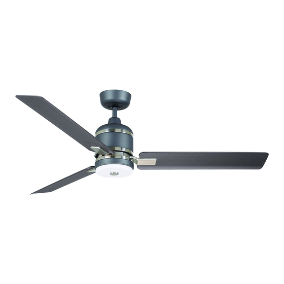
- Page 1 READ AND SAVE THESE INSTRUCTIONS IDEAL ™ 54” Ceiling Fan Owner's Manual Model Numbers CF330BQ00 - Barbeque Black CF330GRT00 - Graphite CF330SW00 - Satin White 15.8 Net Weight: Lbs. 1-800-654-3545 www.emersonfans.com...
-
Page 2: Table Of Contents
Electric Co. Substitution of parts or accessories not 1. To avoid possible shock, be sure electricity is turned designated for use with this product by Emerson could off at the fuse box before wiring, and do not operate result in personal injury or property damage. -
Page 3: Unpacking Instructions
Emerson Electric Co. Substitution of parts or accessories not designated for use with this product by Emerson Electric Co. could result in personal injury or property damage. Open carton containing fan. Remove top half of styrofoam unit. -
Page 4: Tools Needed For Assembly
One 1/4” Blade Screwdriver One Wire Stripper Materials This Emerson Ceiling Fan may be used with the following accessory (purchased separately): SR600 Remote Control. Wiring outlet box and box connectors must be of type required by the local code. -
Page 5: Ceiling Fan Assembly
3. Ceiling Fan Assembly Flip the upper foam pad over and place on a stable SHIPPING working surface. MOTOR HUB RETAINERS (3) Remove the fan motor assembly from the protective plastic bag. Place fan motor assembly on top of the foam pad with the upper motor cover supporting the weight of the motor. -
Page 6: Warning
3. Ceiling Fan Assembly (Continued) NOTE: Take care not to scratch the fan housing 1/4-20 x 1/2" OVAL HEAD SCREWS when installing the blade assemblies. (2 per assembly) Attach the Blade Flange Assembly onto the Fan Motor/ BLADE FLANGE ASSEMBLY Hub by tightening the 1/4-20 x 1/2”... - Page 7 3. Ceiling Fan Assembly (Continued) Remove the Hanger Ball by loosening the Phillips Head GREEN GROUND WIRE Set Screw in the Hanger Ball until the Ball falls freely down the 4.5” Downrod (Figure 5). Remove the Pin from the 4.5” Downrod, then remove the Hanger Ball (Figure 5).
-
Page 8: Warning
3. Ceiling Fan Assembly (Continued) Align the Clevis Pin holes in the Downrod with the holes in the Motor Coupler. Install the Clevis Pin and secure with the Hairpin Clip (Figure 8). HAIRPIN The Clevis Pin must go through the holes in the Motor CLIP MOTOR Coupler. -
Page 9: Ceiling Fan Assembly
3. Ceiling Fan Assembly (Continued) 3.11 Route the two 80” Motor Wires through the Hanger Ball (Figure 11). HANGER BALL Reinstall the Hanger Ball on the Downrod as follows: DOWNROD Position the Pin through the two holes in the Downrod PHILLIPS HEAD and align the Hanger Ball so the Pin is captured in the SET SCREW... -
Page 10: How To Hang Your Ceiling Fan
4. How to Hang Your Ceiling Fan WARNING CEILING The fan must be hung with at least 7' of clearance from floor to blades (Figure 13). WARNING To avoid possible electrical shock, be sure electricity is turned off at the main fuse box before wiring. NOTE: If you are not sure if the outlet box is grounded, contact a licensed electrician for advice, as it must be grounded for safe operation. -
Page 11: How To Hang Your Ceiling Fan
4. How to Hang Your Ceiling Fan (Continued) WARNING The outlet box and joist must be securely mounted and capable of supporting at least 50 lbs. Use only a U.L. outlet box listed as “Acceptable for Fan Support of 22.7 kg. (50 lbs.) or less”. OUTLET BOX TWO SCREWS WARNING... -
Page 12: How To Wire Your Ceiling Fan
Emerson Electric Co. Substitution of parts or accessories not designated for use with this product by Emerson Electric Co. could result in personal injury or property damage. -
Page 13: How To Wire Your Ceiling Fan
5. How to Wire Your Ceiling Fan (Continued) Securely connect the Fan Motor White Wire to the Supply White (neutral) Wire using Wire Connector SUPPLY WHITE (supplied) (Figure 17). (NEUTRAL) LISTED WIRE CONNECTOR FAN MOTOR WHITE WIRE Figure 17 Securely connect the Fan Motor Black Wire to the Supply Black (hot) Wire using Wire Connector (supplied) (Figure 18). -
Page 14: Final Assembly
6. Final Assembly Engage the Fan Motor 2-Pin Wire Connector into the 2-pin Wire Connector of the LED Array (Figure 20). The connection is complete when you hear a soft click. FAN MOTOR 2-PIN WIRE CONNECTOR LED ARRAY 2-PIN WIRE CONNECTOR LED ARRAY Figure 20 Carefully tuck all the wires and connectors into the Light... -
Page 15: Final Assembly
You have now completed the complete assembly of your new ceiling fan. Please call Emerson technical support 1-800-654-3545 if you have any questions about installation and operation of this ceiling fan. -
Page 16: Wall Control Installation
7. Wall Control Installation Preset Memory Feature: Your Emerson receiver is Your Emerson Ceiling Fan/Light Control consists of wall equipped with a preset memory feature. If the AC mounted transmitter and a receiver located inside the supply to the receiver is powered OFF through a wall motor assembly. -
Page 17: Warning
7. Wall Control Installation (Continued) This control is designed to operate only one ceiling fan NOTE: Electric connections should be in accordance with the National Electrical Codes and all Local Codes. Before starting, disconnect power to the circuit at the fuse box or circuit breaker panel. -
Page 18: Warning
7. Wall Control Installation (Continued) SINGLE-POLE INSTALLATION WARNING (One fan controlled by one wall control) Turning off wall switch is not sufficient. To avoid (See Figure 28). possible electrical shock, be sure electricity is turned off at the main fuse or circuit breaker box before wiring. -
Page 19: Warning
7. Wall Control Installation (Continued) 3-WAY INSTALLATION (One fan controlled by two different wall controls) (See Figures 29 and 30). SECONDWALL FAN/LIGHT CONTROL WALL PURCHASE CONTROL SEPARATELY WARNING GROUND Turning off wall switch is not sufficient. To avoid GROUND BLACK possible electrical shock, be sure electricity is turned off at the main fuse or circuit breaker box before LOAD... -
Page 20: Wall Control Installation
7. Wall Control Installation (Continued) 3-WAY WIRING DIAGRAM: WARNING NOTE: Retrofit 3-way installations are likely to include two traveler wires between the two wall Check to see that all connections are tight and that no boxes. In new construction, only one traveler wire Is bare wires are visible at the wire connectors. -
Page 21: Programming The Receiver Operating Frequency & High Speed Conditioning Of Fan Control
8. Programming the Receiver Operating Frequency & High Speed Conditioning of Fan Control -- Important - Read This Section Carefully and Follow the High Speed Conditioning Instructions Closely -- PROGRAMMING THE RECEIVER OPERATING FREQUENCY & HIGH SPEED CONDITIONING OF FAN CONTROL If programming is unsuccessful, retry the previous instructions after cycling the wall control ON/OFF switch to restart the 1 minute programming time period. -
Page 22: Using Your Ceiling Fan
9. Using Your Ceiling Fan WARNING Fan installation must be completed, including the installation of the fan blades, before testing the wall POWER control. INDICATOR LIGHT Your Wall Control has full control of your Fan and Light LIGHT AIRFLOW (Figure 31). INTENSITY DIRECTION BUTTON... -
Page 23: Maintenance
Emerson Electric Co. Substitution of parts or accessories not designated for use with this product WARNING by Emerson Electric Co. could result in personal injury or property damage. The use of any other control not specifically approved for this fan could result in fire, shock and personal injury. -
Page 24: Repair Parts
12. Repair Parts HARDWARE BAG... -
Page 25: Repair Parts
12. Repair Parts Listing Model Numbers Description CF330BQ00 CF330GRT00 CF330SW00 Before discarding packaging material, be certain all parts have been removed. HOW TO ORDER REPAIR PARTS WHEN ORDERING REPAIR PARTS, ALWAYS GIVE THE FOLLOWING INFORMATION: • PART NUMBER • NAME OF ITEM •... -
Page 26: Troubleshooting
8 - 9 feet above the floor for optimal occupied space. Remember to adjust your thermostat airflow. Consult your Emerson Retailer for optional when using your ceiling fan - additional energy and mounting accessories. -
Page 27: Ceiling Fan Limited Warranty
Emerson Air Comfort Ceiling Fan Limited Warranty What The Limited Warranty Covers: "Emerson" "we" "us" "you" "your" "Emerson Ceiling Fan" What The Period Of Coverage Is: No Other Express or Implied Warranty Applies: What We Will Do To Correct Problems:... - Page 28 You should record this data above and keep it in a safe place for future use. Air Comfort Products DIVISION OF EmErSON ElEctrIc cO. 8100 W. Florissant • St. louis, mO 63136 1-800-654-3545...
Need help?
Do you have a question about the CF330GRT00 and is the answer not in the manual?
Questions and answers