Advertisement
Quick Links
Advertisement

Subscribe to Our Youtube Channel
Related Manuals for Axminster MJ12-1600 MK11


Summary of Contents for Axminster MJ12-1600 MK11
-
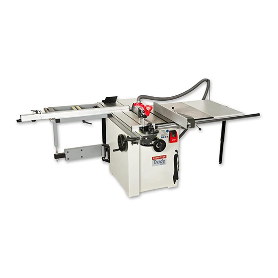
Page 1: Panel Saw
Code 505150 MJ12-1600 MK11 Panel Saw... -
Page 2: Specifications
CONTENT SPECIFICATIONS Install the hold down Install the dust port SAFETY Install the blade guard Safety Instructions for Power Tools Install the dust hose support Additional Safety Instructions for Panel Saws Install dust hoses Protecting Kickback REPLACEMENT & ADJUSTMENT SITE CONSIDERATIONS Replace the main blade GETTING TO KNOW YOUR PANEL SAW Replace and adjusting the scoring blade... - Page 3 1220mm 1220mm 1220mm 1220mm 1220mm Max distance-blade to rip fence Max cross cut length 1600mm 2000mm 2600mm 2800mm 3200mm Max cross cut width 1350mm 1350mm 1350mm 1350mm 1350mm Packing size 936 756 1040mm 936 756 1040mm 1580 756 1009mm 1580 756 1009mm 1580 756 1009mm 1640 240 310mm 2040 240 310mm...
-
Page 4: Safety Instructions For Power Tools
SAFETY should be in accordance with amperage rating. An undersized cord will cause a drop in line voltage resulting in loss of power and overheating. Your extension cord must also contain a ground wire. Always repair or replace extension cords if they For Your Own Safety, Read Instruction Manual become damaged. - Page 5 Additional Safety Instructions for Panel Saws No list of safety guidelines can be complete. Every shop environment is different. Always consider safety first, as it applies to your 1. SAFETY ACCESSORIES. Always use the blade individual working conditions. Use this and guard and riving knife on all ''through-sawing'' other machinery with caution and respect.
-
Page 6: Site Considerations
SITE CONSIDERATIONS General Condition: 1 .Electrical connection: Steady state voltage: 0.9-1.1 of nominal voltage. Frequency: 0.99-1.01 of nominal frequency continuously; 0.98-1.02 short time The mains connection must have maximum16A fuse. Electrical supply which has protection devices of under-voltage, over-voltage, over-current as well as a residual current device (RCD) which maximum residual current rated at 0.03A. - Page 8 A. Crosscut Table-Provides a wide, stable platform for K. Blade Angle Hand-wheel-Adjust the angle of the supporting full-size panels during crosscutting saw blades. operations. L. Mitre Gauge-This gauge aligns the wood for a B. Flip Stops-Used for quick measurements for cross-cut.
- Page 9 UNPACKING Clean Up The Sliding Panel Saw is shipped from the manufacturer in a carefully packed crate. If you The unpainted surfaces are coated with a light oil to discover the machine is damaged after you have protect them from corrosion during shipment. Remove signed for delivery, please call Customer Service this protective coating with a solvent cleaner or citrus- immediately for advice.
- Page 10 ASSEMBLY Center the extension table over the edges and tap it. Check the surface alignment. Moving & Placing Saw Base Unit The Sliding Panel Saw is a heavy machine. Serious personal injury may occur if safe moving methods are not followed. To be safe, you will need assistance and power equipment when moving the shipping crate and removing the machine from the crate.
- Page 11 Install the main blade elevation & angle handwheel 1. Fitting the elevation handwheel(1) and angle handwheel (2) onto the elevation and angle shaft. Install the rip fence rail Screw the blade lock knob(3) onto the elevation Handwheel. 1. insert 4-M10x80 hex head bolts into major table and extension tables.
- Page 12 2 .Place the cross-cut table support (A) onto the swing arm assembly, and hand tighten the lock nuts. The Adjust the sliding panel level: support needs further adjustment. 1 . Place a level rule (cross cut fence) on to major table Install the Sliding panel assembly and sliding panel.
- Page 13 Install the cross cut fence Install the dust port Place dust port onto bottom rear panel, 1.Drop the cross cut fence into the forward or rear guide pin hole. tighten it with 4 M6x12 pan head screws washers and nuts (nuts inside stand). 2.Tighten the knurled nut.
- Page 14 Install dust hoses 1. Install the 2" dust hose onto the blade guard with 2" hose clamp. 2. Put the 2" dust hose onto dust hose support, keep free with the working table. 3. Another end of 2" dust hose clamps to the main dust port on the bottom of rear panel.
-
Page 15: Replacement And Adjustment
REPLACEMENT & ADJUSTMENT Replace the main blade Disconnect the saw from the power source! The main blade dimension suitable for MJ12B machine is 254x30x3( outer diameter, core diameter, thickness), 305x30x3, 315x30x3mm. Replace and adjusting the scoring blade But any time you change blade thickness, the appropriate sized riving knife and scoring blade must also be changed to match the size of main Disconnect the saw from the power source! - Page 16 To align scoring blade: Loosen the clamping screw (A). Lateral adjustment is made via adjusting screw (B). the height setting is made via setting screw (C). retighten the clamping screw (A). Adjust the scoring blade laterally so it is in line with the main saw-blade.
- Page 17 2. Raise the main blade up as far as it will go. 3. Mark the center of the blade with a felt tip pen. This will allow you to take your measurements from the exact same place on the blade. 4.
- Page 18 OPERATIONS 3. Install the crosscut fence in the guide pin holes and lock it in place with the knurled nut. Note First, drop the crosscut fence into the forward guide pin hole, turn the "Z"lock plate to align the fence, then tighten the knurled nut. Your safety is important.
- Page 19 This machine has the capability of crosscutting workpieces while using the hold down w/mitre gauge . 5. Mount the hold down arm onto the stud and lock the work-piece in place. 6. Once all the necessary safety precautions have been taken, perform the cutting operation.
- Page 20 Miter Cutting Note If the workpiece extends to the left of the saw blade more than 1200mm, then the crosscut fence The cross cut table built two scales for forward and rear slide needs to be extended. mount fence to perform mitre cut. 4.
- Page 21 ELECTRICAL MAINTENANCE Main switch This machine is equipped with a knee touch no-volt release main switch and a limit switch. Always disconnect power to the machine before The main switch is equipped a large size touch panel, performing maintenance. Failure to do this may during performance cutting work, any part of man body result in serious personal injury.
- Page 22 LIMIT SWITCH ELECTRO-MAGENETIC SWITCH LIMIT SWITCH ELECTRO-MAGENETIC SWITCH...
-
Page 23: Troubleshooting
TROUBLESHOOTING Disconnect power to the machine when performing any troubleshooting. Failure to do this may result in serious personal injury. -
Page 24: Parts List & Diagrams
PARTS LIST & DIAGRAMS Parts List Diagram A Description Description Pan head screw M6x12 A-28 Washer 4mm Washer 6mm A-29 Pan head screw M4x12 Dust port A-30 Hold screw, push stick Right panel, saw base A-31 Push stick A-15 Washer 5mm A-32 Internal guard A-18... - Page 25 Parts List Diagram B cont... Description Description Lower support B-43 B-71 Hex nut M10 Adjustable disc B-44 B-72 Lock guide Scew guide B-51 B-73 T-nut, push handle Taping screw ST4.2x12 B-52 B-74 Set screw M8x12 End cap, sliding panel B-53 B-75 Insert, ball frame Allen screw M5x8...
- Page 26 Parts List Diagram C cont... Description Description C-49 Ball bearing C-79 Hex head screw M6X20 C-50 Tube C-80 Allen screw M6X20 C-51 Wheel handle C-81 Hex nut M6 C-52 Thread C-82 Set screw M8X8 C-53 Spring C-83 Flat hey 18X35 C-54 Washer C-84...
- Page 27 Parts List Diagram E Description Description E-42 Hex screw M8x30 Scale, cross cut table E-43 Hex screw M10x25 Washer 6mm E-44 Sunk head screw M6x12 Scale, cross cut table E-45 T-nut, extension fence Allen screw M6x12 E-46 Lock plate Eccentric cam E-47 T-block Washer 8mm...
- Page 28 Parts List Diagram G Description Description G-20 Dust hose support Rear extension table G-21 Washer 6mm Washer 8mm G-22 Hex screw M6x20 Hex nut M8 G-23 Hex nut M6 Set screw M6x12 G-26 Adjustable disc Hex screw M8x16 G-27 Lower, support Flat washer 10mm G-28 Disc insert...
- Page 37 Parts List Diagram K Description Description Left guard Cross head screw M5X8 K-1. K-3. Right guard Washer M5 K-2. K-4.
- Page 38 Normal wear and tear; misuse, abuse and neglect are excluded and the machine should not have been engineering machines, Axminster Air compressors and Air Tools, and bench top grinders - no modified in any way. Please do not attempt to service the product without first contacting us; we are registration necessary just proof of purchase.
Need help?
Do you have a question about the MJ12-1600 MK11 and is the answer not in the manual?
Questions and answers