
Related Manuals for Axminster Bandsaw


Summary of Contents for Axminster Bandsaw
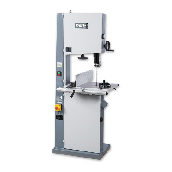
- Page 1 Code 103472 Original Instructions AT3086B Bandsaw AT&M: 28/06/2018 BOOK REF : 103822...
-
Page 2: Eu Declaration Of Conformity
Electro-magnetic Motor Brake Switch Compact Mitre Fence Changing the Saw Blade 30-31 Maintenance 32-33 Bandsaw Blade Information 34-35 Bandsaw Trouble Shooting/Accessories UJK Technology Bandsaw Buddy Exploded Diagrams/Lists 38-39-40-41-42-43-44-45-46-47 Wiring Diagram Notes 49-50-51 EU Declaration of Conformity Cert No: SBW-350H EU Declaration of Conformity Axminster Tools &... -
Page 3: What's Included
What’s Included Quantity Item Model Number AT3086B Trade Bandsaw Blade 3,086.1mm (121.5”) long, mounted on saw but not tensioned. Cast Iron Table Fence Assembly: Bags Comprising: Front Fence Rail with Scale Mitre Fence Assembly Fence a) Threaded lever with washer... - Page 4 What’s Included...
- Page 5 What’s Included...
-
Page 6: General Instructions For 230V Machines
General Instructions for 230V Machines The following will enable you to observe good working • Carry out a final check e.g. check the cutting tool practices, keep yourself and fellow workers safe and maintain is securely tightened in the machine and the correct your tools and equipment in good working order. -
Page 7: Specification
B. CAUTION! take care, the blade is sharp. Lift the bandsaw off the pallet using the ‘Eye Bolt Lifting Ring’ mounted to the top of the bandsaw. Place the saw on a flat surface, ascertain the orientation of the machine and move it to its desired position in the workshop. - Page 8 Main Assembly Step 1 Remove the table insert and the table shipment Fig 09-10 cap head bolt and nut and place aside, see figs 04-05. Lift the table (1), slide the blade through the table slot, rotate the table round and lower the table on to the tilt quadrant assembly, see fig 06-07.
- Page 9 Main Assembly Step 4 Locate the table alignment pin handle (13) and the large washer and nut (21). Insert the washer over the thread and screw on the nut, giving sufficient clearance between washer and nut, see fig 13. Insert the threaded handle into the slot in the cast iron table (1) and tighten so the nut clamps down in the machined recess, see fig 14.
- Page 10 Main Assembly Spanner Step 4 Locate the fence (3), M8 lift and shift handle/ M8 large washer (6) and threaded ‘T’ slot insert (7). Place the large NOTE: The fence (3) has two positions, vertical and washer over the thread of the lift and shift handle (6), introduce horizontal for cutting narrow pieces, see fig 24-25-26.
- Page 11 Main Assembly Fig 30 Fence Assembly Support Bracket The bracket helps to support the fence assembly when the fence is in position up against the saw frame to utilise the maximum width of the table (1) Locate the fence assembly support bracket (19) and the two M6 cap head screws (20).
- Page 12 Step 6 Using the supplied Hex key (c) screw the two grub screws (b) into threaded holes to the end of the steel bar, see fig 36-37. The grub screws can be adjusted so the mitre fence runs smoothly in the bandsaw tables ‘T’ Slot.
-
Page 13: Machine Dimensions
Machine Dimensions 740mm Code: 103472 AT2086B Bandsaw... -
Page 14: Illustration And Parts Description
Illustration and Parts Description Eye bolt lifting ring Blade tracking window Upper door locking knob Upper wheel door Upper blade guide adjusting wheel Wheel tensioning scale Upper blade guide and guard Blade tensioning wheel Fence Selector switch Upper blade guide ON/OFF buttons with emergency stop shroud Mitre fence... - Page 15 Illustration and Parts Description Key release emergency stop, press Upper blade guide height the button to stop the bandsaw and scale and pointer turn the key to release it Electro-magnetic motor brake switch NVR switch control assembly Blade tracking window...
- Page 16 Illustration and Parts Description Wheel tension assembly Micro door switch Blade tracking window Upper saw wheel Upper wheel door Saw blade Saw table Blade tensioning scale/pointer Table insert Dust extraction outlet Drive pulley Lower saw wheel Lower wheel door Drive pulley Storage compartment Storage door...
- Page 17 Illustration and Parts Description Upper blade thrust bearing (A) Upper bearing blade guides (A) Table level angle bracket Clamping screw (B) Blade guide adjusting knob (B) with adjustable stop Blade guide fore and aft clamping screw (C) Guide assembly clamping screw (C) bolt for 90˚...
- Page 18 Illustration and Parts Description Quick release tensioning lever for Upper blade guide clamp changing the blade Tracking control knob Tracking control lock Blade tensioning wheel Tilt quadrant assembly Table levelling angle bracket with adjustable stop bolt Dust extraction outlet Motor...
- Page 19 Illustration and Parts Description Fence assembly support bracket (A) Fence lift & shift clamping handle (B) Quick release tensioning blade lever (A) Blade tensioning wheel Tracking control knob (B), Locking handle (C) Tilt quadrant clamping handle (A), Tilt quadrant rack and pinion adjusting handle (B), Tilt quadrant scale pointer (A) Tilt quadrant scale (C), Lower thrust bearing adjusting knob (D) and adjusting screw (B)
-
Page 20: Setting Up The Saw
Setting Up the Saw MAKE SURE THE SAW IS DISCONNECTED FROM THE MAINS SUPPLY! Checking the Table is Square Levelling stop bolt Step 1 Loosen the clamping handle beneath the table, see fig 39. Lower the table by turning the tilt quadrant rack and pinion adjusting handle, until it’s against the stop. - Page 21 51. Fig 51 Code 101807 Step 3 Place the Bandsaw Buddy on the blade as shown in fig Setting the Fence 52. Move the fence up close to the alignment tool, lock in place Step 1 To make sure the guide fence is at 90˚, line up the guide...
- Page 22 Step 2 Apply some tension to the blade by turning the tensioning wheel clockwise, spin the top wheel by hand and Step 4 Remove the bandsaw buddy if not done so already. check that the blade remains centrally on the tyre, see fig 58-59.
- Page 23 Setting Up the Saw Fig 61-62 Fig 63 Step 7 If it doesn’t, adjust the tracking until correct. NOTE: Make very small adjustments and wait for the saw to react before you adjust again, sometimes the reaction is not instantaneous. Step 8 Once you are satisfied that the tracking is correct press the ‘RED’...
- Page 24 Setting Up the Saw Fig 69-70 Thrust bearing 2mm behind the blade Step 3 Loosen the Hex screw (C) holding one of the guide 2mm behind the gullets bearings and move to approximately 0.5mm from each side of the blade. NOTE: A sheet of A4 photocopy paper is approximately 0.5mm thick.
- Page 25 (2), see fig 75 and press the ‘GREEN’ button to start the saw. Allow the bandsaw to run for several minutes, check that the blade is still tracking correctly, there is no excessive vibration, etc. After several minutes switch off and allow the blade to come to a complete stop.
-
Page 26: Operating Instructions
HSE Health and Safety Executive WARNING! IF THE SAW JAMS! SWITCH OFF IMMEDIATELY. To operate the bandsaw correctly, it is recommended to visit the HSE (Health and Safety Executive) website at www.hse.gov.uk and read the information on the safe practices. - Page 27 Operating Instructions Setting the Table Angle DISCONNECT THE SAW FROM THE MAINS SUPPLY! The cast iron table (1) can be tilted 0-45˚ degrees. The tilt 45˚ quadrant comprises a scale/pointer, clamping handle (A) to lock the table in set positions and a rack and pinion operating handle (B) to manoeuvre the table at set angles.
- Page 28 Fig 84 NVR switch assembly and has three positions, see fig 83. • Position (0) engages the motor brake to prevent the bandsaw blade from moving and to isolate the bandsaw to prevent it from being started accidentally, see fig 84.
- Page 29 Compact Mitre Fence The compact mitre fence head features positive stops at 0°, The bar is 320mm long with a removable locking washer 22.5°, 30°, 45°, 60°, 67.5° and 90°, both left and right. This gives making it usable with any standard 19 x 9.5mm (3/4” x 3/8”) you 13 preset common angles in total.
-
Page 30: Changing The Saw Blade
Changing the Saw Blade Step 1 Put the table back to the level position if it has been tilted. Set the upper blade guide assembly approximately midway in the throat. Open the top and bottom wheel doors, remove the mitre fence assembly and remove the table insert, Tension released see figs 87. - Page 31 Changing the Saw Blade Fig 91 Upper blade guides Step 5 Open up all blade guides so that they are clear of the blade. Hold the blade approximately midway on either side of the loop and feed it into the table slot. When you get to the table insert cutout void, work the left side of the loop into the slot in the guard in the neck of the main saw frame.
-
Page 32: Maintenance
Maintenance Fig 99-100 DISCONNECT THE SAW FROM THE MAINS SUPPLY! Daily • Keep the machine clean. • Check the saw blade for missing teeth and cracks, see fig 97. • Spray Axcaliber Dry lubricant on the bare metal surfaces. Fig 97 Check for missing teeth and cracks in the blade... - Page 33 NOTE: The guide and thrust bearing should turn freely when the bandsaw is in use. If the bearings are stiff, clean them as mentioned above. If this still does not rectify the problem the bearings are worn and will need to bereplaced.
- Page 34 Blades are cut accurately to length then, speed should be used at all times with a blade tooth pitch this using an IDEAL bandsaw blade welder, a high voltage current is fine. passed through the blade to achieve a precision butt weld.
- Page 35 • Also used for cutting metal on horizontal bandsaws. Blades are available in three variable pitch forms 4-6tpi, 6-10tpi and 10-14tpi. High Carbon Bandsaw Blades • General purpose range of blades for wood and metal cutting. • Comprehensive range of lengths widths and tooth configuration.
-
Page 36: Bandsaw Blades
Bandsaws are relatively simple machines and with all Below is the list of top recommended accessories and machinery regular servicing (preventative maintenance) is up-sell items for the bandsaw. Please visit our website at essential to get the best from your saw. axminster.co.uk Axminster •... - Page 37 • Scale on the tip helps set fence for cutting veneers or thin • A scale on the tip helps set the bandsaw fence for cutting veneers or thin boards. Holes along the Buddy’s length at boards 12.5mm intervals allow you to draw arcs or circles in 25mm...
- Page 38 Exploded Diagrams/Lists Main Saw Assembly (SBW-3501H3)
- Page 39 Exploded Diagrams/Lists ITEM PART NO PARTS DESCRIPTION SIZE SR060200 HEX SOCKET BOLT M6x10 NF050800 135004 LIMPID PIECE SR060400 HEX SOCKET BOLT M6x20 SJ059400 HEX SOCKET BOTTOM M6x10 HEAR SCREW 135067 BUSHING WS050000 SPRING WASHER 995101 RING WF051210 FLAT WASHER M5x12 130485 MACHINE BODY NL081300...
- Page 40 Exploded Diagrams/Lists Main Saw Assembly (SBW-3501H3)
- Page 41 Exploded Diagrams/Lists 709412 STRAIN RELIEF PG11 SS069300 SET SCREW M6x12 IC130486 EMERGENCY SWITCH VDE0.75x2Cx1M IC130485 POWER CORD VDE1.5x3Cx3.1M CORD SJ080400 HEX SOCKET BOTTOM M8x20 HEAD SCREW 136475 PLATE WS080000 SPRING WASHER ST049200 TAPPING SCREW M4x8 AB135530 GUIDE BRACKET(ASM) WS100000 SPRING WASHER NH081300 WF102320 FLAT WASHER...
- Page 42 Exploded Diagrams/Lists 14inch Fence Assembly (SBW-3501H3) ITEM PART NO DESCRIPTION SIZE 198004 FIXED LUMP 198018 FIXED BASE NH081300 198002 ADJUST BASE SF049100 PAN HEAD BOLT W/FLANGE M4x6 198003 FIXED SHAFT 198014 GUARD PIECE 198005 SHAFT 200527 MOVING PLATE 198006 SPRING WASHER ST039300 TAPPING SCREW M3.5xl2...
- Page 43 Exploded Diagrams/Lists Trunnion Support Bracket ASM (SBW-3501H3) NH061000 ITEM PART NO PARTS DESCRIPTION SIZE 135253 ADJUST PLATE WF081820 FLAT WASHER M8x18 SP059200 PAN HEAD BOLT W/FLANGE M5x8 NL081300 NYLON NUT SR069400 HEX SOCKET BOLT M6x16 SP049100 PAN HEAD BOLT M4x6 SR061000 HEX SOCKET BOLT M6x50...
- Page 44 Exploded Diagrams/Lists AB135530 Guide Bracket A (SBW-3501H3) ITEM PART NO PARTS DESCRIPTION SIZE 135530 UPPER GUIDE TUBE SR060200 HEX SOCKET BOLT M6x10 SP040200 PAN HEAD BOLT M4x10 NH040700 136465 EXTEND GEAR SN049200 COUNTER SUNK BOLT M4x8 136466 RACK WS080000 SPRING WASHER SR089400 HEX SOCKET BOLT M8x16...
- Page 45 Exploded Diagrams/Lists AB135092 UpperSaw Blade Adjustment ASM (SBW-3501H3) ITEM PART NO DESCRIPTION SIZE SR069400 HEX SOCKET BOLT M6xl6 135057 UPPER GUIDE SUPPORT BLOCK 135053 ADJUST BAR 135091 UPPER BLADE GUIDE SUPPORT 135090 BIAS SHAFT RS150000 RING BB620202A BALL BEARING 6202ZZ 136445 HANDLE BUSHING SR060703...
- Page 46 Exploded Diagrams/Lists Compact Mitre Fence PART DISCRIPTION HANDLE FENCE METAL WASHER 1MM PVC WASHER 2.5MM KNURLING KNOB MITRE GAUGE DIAMOND KNOB 3/8” FLIP STOP T-SHAPED SCREW RULER TAPE SQUARE NUT...
- Page 47 Exploded Diagrams/Lists ITEM PART NO DESCRIPTION SIZE 130465 LOCK KNOB M8x5 198013 HANDLE 200527 MOVING PLATE NH081300 WF082320 FLAT WASHER M8x23X2 SH060400 HEX HEAD BOLT M6x20 VS060000 SPRING WASHER VF061310 FLAT WASHER M6x013 ITEM PART NO DESCRIPTION SIZE SR069300 HEX SOCKET BOLT M6xl2 WF061620 FLAT WASHER...
-
Page 48: Wiring Diagram
Wiring Diagram... - Page 49 Notes...
- Page 50 Notes...
- Page 51 Notes...
- Page 52 The Axminster guarantee is available on Craft, Trade, Engineer, Air Tools & CNC Technology Series machines Buy with confidence from Axminster! So sure are we of the quality, we cover all parts and labour free of charge for three years! For more information visit axminster.co.uk/3years...
Need help?
Do you have a question about the Bandsaw and is the answer not in the manual?
Questions and answers