Table of Contents
Advertisement
Quick Links
Advertisement
Table of Contents

Related Manuals for National Instruments NI 951x


Summary of Contents for National Instruments NI 951x
- Page 1 Motion Control NI 951x User Manual NI 951x User Manual July 2009 372153B-01...
- Page 2 Thailand 662 278 6777, Turkey 90 212 279 3031, United Kingdom 44 (0) 1635 523545 For further support information, refer to the Technical Support and Professional Services appendix. To comment on National Instruments documentation, refer to the National Instruments Web site at and enter ni.com/info the info code feedback ©...
-
Page 3: Important Information
Instruments Corporation. National Instruments respects the intellectual property of others, and we ask our users to do the same. NI software is protected by copyright and other intellectual property laws. Where NI software may be used to reproduce software or other materials belonging to others, you may use NI software only to reproduce materials that you may reproduce in accordance with the terms of any applicable license or other legal restriction. - Page 4 Operation of this hardware in a residential area is likely to cause harmful interference. Users are required to correct the interference at their own expense or cease operation of the hardware. Changes or modifications not expressly approved by National Instruments could void the user’s right to operate the hardware under the local regulatory rules.
-
Page 5: Table Of Contents
About the NI 951x Drive Interface Modules ..............1-1 Features......................1-1 Hardware ......................1-1 What You Need to Get Started ..................1-2 Using the NI 951x Modules in Scan Interface Mode ........1-2 Using the NI 951x Modules in LabVIEW FPGA Interface Mode....1-3 Safety Information ......................1-3 Special Conditions for Marine Applications ...........1-3 Optional Equipment .......................1-4... - Page 6 Digital Outputs....................3-17 Chapter 4 Accessory and Cable Connections Connection to P7000 Series Stepper Drives..............4-1 NI 951x Connection Accessories .................. 4-5 37-Pin Terminal Block Pin Assignments............4-5 Signal Connection Recommendations................4-7 General Connection Recommendations............4-7 Limit and Digital Input Connection Recommendations ......... 4-8 Encoder Connection Recommendations ............
-
Page 7: Specifications
Contents Appendix A Specifications Appendix B Position Command Connections Appendix C Technical Support and Professional Services Glossary Index © National Instruments Corporation NI 951x User Manual... -
Page 8: About This Manual
This font is also used for the proper names of disk drives, paths, directories, programs, subprograms, subroutines, device names, functions, operations, variables, filenames, and extensions. © National Instruments Corporation NI 951x User Manual... -
Page 9: Related Documentation
Contents tab. • LabVIEW Help—Contains LabVIEW, LabVIEW Real-Time Module, and LabVIEW FPGA Module programming concepts, instructions, and reference information. Access the LabVIEW Help by selecting Help»Search the LabVIEW Help from within LabVIEW. NI 951x User Manual ni.com... -
Page 10: Introduction And Installation
This chapter includes information about the features of the National Instruments 9512, 9514, and 9516 drive interface modules. Note The remainder of this document will refer to these modules collectively as NI 951x modules. About the NI 951x Drive Interface Modules The NI 951x drive interface modules are a family of C Series motion modules. -
Page 11: What You Need To Get Started
Procedures (Scan Interface) section of the LabVIEW Help for more information about using C Series modules in Scan Interface mode. To set up and use the NI 951x drive interface modules in Scan Interface mode, you must have the following items: ❑... -
Page 12: Using The Ni 951X Modules In Labview Fpga Interface Mode
(FPGA Interface) section of the LabVIEW Help for more information about using C Series modules in LabVIEW FPGA Interface mode. To set up and use the NI 951x drive interface modules in LabVIEW FPGA Interface mode, you must have the following items: ❑... -
Page 13: Optional Equipment
Optional Equipment National Instruments offers several options for connecting NI 951x drive interface modules to external stepper drives or servo amplifiers including the following: •... -
Page 14: Hardware Overview
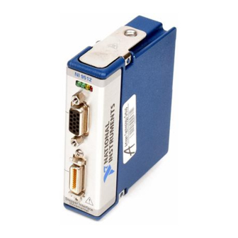
Hardware Overview This chapter presents an overview of the National Instruments 951x drive interface module hardware, including connections and connector pin assignments. The following figure shows the NI 951x module. Figure 2-1. NI 951x Module © National Instruments Corporation NI 951x User Manual... -
Page 15: Ni 951X Connections
Refer to the NI SoftMotion Module book of the LabVIEW Help for information about chassis, slot, or software restrictions. Connect the module to a drive and other I/O using the NI 9512-to-P7000 Stepper Drives Connectivity Bundle, the NI 951x Cable and Terminal Block Bundle, or a custom cable for direct connectivity. - Page 16 The NI 9512 requires an external power supply. You can connect the external power Note supply to the V input provided on the DSUB or MDR connector. Do not connect more than one external power supply to the module. © National Instruments Corporation NI 951x User Manual...
-
Page 17: Ni 9514 Connections
Refer to the NI SoftMotion Module book of the LabVIEW Help for information about Note chassis, slot, or software restrictions. Connect the module to a 37-pin terminal block using the NI 951x to 37-pin cable, or use a custom cable for direct connectivity. Connect the NI 9514 module to an external power supply. - Page 18 V input provided on the DSUB or MDR connector. Do not connect more than one external power supply to the module. Do not connect anything to pins marked Reserved. Caution © National Instruments Corporation NI 951x User Manual...
-
Page 19: Ni 9516 Connections
Refer to the NI SoftMotion Module book of the LabVIEW Help for information about chassis, slot, or software restrictions. Connect the module to a 37-pin terminal block using the NI 951x to 37-pin cable, or use a custom cable for direct connectivity. - Page 20 V input provided on the DSUB or MDR connector. Do not connect more than one external power supply to the module. Do not connect anything to pins marked Reserved. Caution © National Instruments Corporation NI 951x User Manual...
-
Page 21: User Connectors
Figure 2-7. NI 9516 Block Diagram User Connectors The NI 951x has two connectors, a 15-pin DSUB drive interface connector and a 20-pin MDR feedback connector. The 15-pin DSUB includes command signals for interfacing with stepper drives or servo amplifiers, 0 to 30 V general-purpose digital input and digital output lines, and an input for power connection. -
Page 22: Ni 9512 Connectors
Digital Output 0 Direction (CCW)+ Step (CW)+ Position Command Connections, for position command signal Refer to Appendix B, Note information and information about connecting the NI 9512 module to position command drives. © National Instruments Corporation NI 951x User Manual... - Page 23 Encoder 0 Phase A+ Encoder 0 Index+ Encoder 0 Phase A– Encoder 0 Index– Encoder 0 Phase B+ Position Capture +5 V OUT Encoder 0 Phase B– Position Compare Figure 2-8. NI 9512 MDR Connector Pin Assignments NI 951x User Manual 2-10 ni.com...
-
Page 24: Ni 9514 Connectors
Do not connect anything to pins marked Reserved. Table 2-2. NI 9514 DSUB Control Connector Pin Assignments Connector Signal Drive Command COM Drive Enable Reserved Reserved Reserved Drive Command Digital Input 1 Reserved Reserved Reserved Reserved Reserved © National Instruments Corporation 2-11 NI 951x User Manual... - Page 25 Encoder 0 Phase A+ Encoder 0 Index+ Encoder 0 Phase A– Encoder 0 Index– Encoder 0 Phase B+ Position Capture +5 V OUT Encoder 0 Phase B– Position Compare Figure 2-9. NI 9514 MDR Connector Pin Assignments NI 951x User Manual 2-12 ni.com...
-
Page 26: Ni 9516 Connectors
Table 2-3. NI 9516 DSUB Control Connector Pin Assignments Connector Signal Drive Command COM Drive Enable Reserved Reserved Reserved Drive Command Digital Input 1 Reserved Reserved Reserved Reserved Reserved © National Instruments Corporation 2-13 NI 951x User Manual... - Page 27 Encoder 0 Phase A+ Encoder 0 Index+ Encoder 0 Phase A– Encoder 0 Index– Encoder 0 Phase B+ Position Capture +5 V OUT Encoder 0 Phase B– Position Compare Figure 2-10. NI 9516 MDR Connector Pin Assignments NI 951x User Manual 2-14 ni.com...
-
Page 28: Led Indicators
Chapter 2 Hardware Overview LED Indicators The NI 951x has four LEDs to display status information. 1 Axis Status (Green) 3 Limit Active (Yellow) 2 Encoder Active (Green) 4 Axis Fault (Red) Axis Status The Axis Status LED (green) has three states to display axis status. -
Page 29: Limit Active
The Axis Fault LED (red) has two states to indicate the presence of a fault in the system. Refer to the NI SoftMotion Module book of the LabVIEW Help for a list of module faults and troubleshooting information. • Off—No module faults. • Lit—One or more module faults. NI 951x User Manual 2-16 ni.com... -
Page 30: Signal Connections
Signal Connections This chapter describes how to make input and output signal connections directly to the National Instruments 951x drive interface modules and describes the associated I/O circuitry. Table 3-1 describes the signals available on the modules. Table 3-1. NI 951x Signal Reference... - Page 31 Chapter 3 Signal Connections Table 3-1. NI 951x Signal Reference (Continued) Signal Signal Name Signal Overview Encoder 0 Encoder 0 Phase A+ • Primary encoder for position or velocity feedback Encoder 0 Phase A– • RS-422 differential, compatible with Encoder 0 Phase B+ single-ended encoders •...
- Page 32 Chapter 3 Signal Connections Table 3-1. NI 951x Signal Reference (Continued) Signal Signal Name Signal Overview Position Capture Position Capture • High-speed position capture input • 5 V TTL input • 100 ns minimum pulse width • ±2 mA max input current •...
-
Page 33: Power Connections
Chapter 3 Signal Connections Power Connections The NI 951x drive interface modules require an external power supply. An onboard regulator generates a +5 V output supply from the V input for both internal and external usage. The positive terminal for the power supply and the reference must be connected to COM. - Page 34 +5.5 V. Do not connect any unused output lines directly to COM, +5 V OUT, or V Caution Leave all unused output lines unconnected. © National Instruments Corporation NI 951x User Manual...
- Page 35 Refer to Appendix A, Specifications, for more information. Note Refer to Appendix B, Position Command Connections, for position command signal descriptions and information about connecting the NI 9512 module to drives that support position command mode. NI 951x User Manual ni.com...
-
Page 36: Servo Command Signals
Additional Drive Signals Drive Enable Use the Drive Enable output on the NI 951x module to control the enable function of a drive. The enable input on the drive must be active for the drive to acknowledge commands from the module. The Drive Enable signal is active during normal operation and deactivated upon a fault or error condition. - Page 37 Figure 3-4. Drive Enable Circuit Configured for Sourcing PNP (Sourcing) NI 951x Input Device NI 951x V Sourcing Drive Enable or Circuit Digital Output Drive Enable or Digital Output Configured For Sinking V– (Reference) Figure 3-5. Drive Enable Circuit Configured for Sinking NI 951x User Manual ni.com...
-
Page 38: Motion I/O Signals
Forward Limit, Reverse Limit, and Home inputs are not required for basic motion control. These inputs are part of a system solution for complete motion control. National Instruments recommends using limits for personal safety, as well as to Caution protect the motion system. - Page 39 Figure 3-6. Limit Input Configured for Sinking NPN (Sinking) Output Device NI 951x NI 951x V Limit, Home, or Digital Input Configured For Sourcing Limit, Home, or Digital Input V– (Reference) Figure 3-7. Limit Input Configured for Sourcing NI 951x User Manual 3-10 ni.com...
-
Page 40: Encoder Inputs
All encoder signals are digitally filtered and provide programmable filter frequencies. The filter settings are based on the software-programmable maximum velocity rate. Refer to the NI SoftMotion Module book of the LabVIEW Help for more information about encoder filter settings. © National Instruments Corporation 3-11 NI 951x User Manual... -
Page 41: Encoder Phase A/Phase B
Index pulse position and establish a reference zero position for absolute position control. Figure 3-10 shows the single-ended representation of the encoder pulses. Phase A Phase B Index Figure 3-10. Incremental Encoder Phasing Diagram NI 951x User Manual 3-12 ni.com... -
Page 42: Encoder Input Circuit
Module book of the LabVIEW Help for more information about encoder settings. Encoder Input Circuit The NI 951x drive interface modules support RS-422 differential and single-ended inputs for Phase A, Phase B, and Index signals, and provide a +5 V output for encoder power. -
Page 43: Position Capture Input And Position Compare Output
Signal Connections Position Capture Input and Position Compare Output The NI 951x drive interface modules have a high-speed Position Capture input and Position Compare output. These signals are useful for high-speed synchronization of motion with actuators, sensors, vision and data acquisition devices, and other components in the complete motion system. -
Page 44: Digital I/O Signals
Chapter 3 Signal Connections Digital I/O Signals Digital Inputs The NI 951x drive interface modules have the following digital input signals: • Digital Input <0..1>—The NI 951x drive interface modules include two 5 kHz digital inputs compatible with 0 to 30 V logic outputs. - Page 45 Figure 3-13. Digital Input Configured for Sinking NPN (Sinking) Output Device NI 951x NI 951x V Limit, Home, or Digital Input Configured For Sourcing Limit, Home, or Digital Input V– (Reference) Figure 3-14. Digital Input Configured for Sourcing NI 951x User Manual 3-16 ni.com...
-
Page 46: Digital Outputs
If you are connecting to sinking inputs, configure the output type to sourcing. Conversely, if you are connecting to sourcing inputs, configure the output type to sinking. © National Instruments Corporation 3-17 NI 951x User Manual... - Page 47 PNP (Sourcing) NI 951x Input Device NI 951x V Sourcing Drive Enable or Circuit Digital Output Drive Enable or Digital Output Configured For Sinking V– (Reference) Figure 3-18. Digital Output Circuit Configured for Sinking NI 951x User Manual 3-18 ni.com...
-
Page 48: Accessory And Cable Connections
Accessory and Cable Connections This chapter describes the accessory and cable connections for the National Instruments 951x drive interface modules, including connection diagrams and cable pin assignments, custom cable information, and additional information about software-mappable signals. Connection to P7000 Series Stepper Drives... - Page 49 Connect the drive power supply to the P7000 drive. Update the axis configuration settings in software for proper operation with the P7000 drives. Refer to NI 951x to P7000 Drive Configuration Settings in the NI SoftMotion Module book of the LabVIEW Help for axis setting information.
- Page 50 5 Stepper Motor 8 P7000 Command I/O Connector 2 NI 9512 MDR Connector 6 NI 9512-to-P7000 9 NI 951x MDR to Terminal Block Cable 3 NI 9512 DSUB Connector Direct Connect Cable 10 37-pin Terminal Block 4 NI 9512 Module...
- Page 51 Encoder 0 Index– Encoder 0 Phase A– Encoder 0 Phase B+ +5V OUT Position Capture Position Compare Encoder 0 Phase B– Reserved Reserved Reserved Reserved Shield Figure 4-2. NI 9512 37-Pin Terminal Block MDR-Only Pin Assignments NI 951x User Manual ni.com...
-
Page 52: Ni 951X Connection Accessories
This section contains information about the NI 951x 37-pin terminal blocks and cables, including pin assignments for each module. Figure 4-3 shows the NI 951x module connected to the 37-pin terminal block using the NI 951x to 37-pin cable. Figure 4-3. NI 951x Module and 37-Pin Terminal Block... - Page 53 Drive Command COM Reserved † † † † Drive Enable Digital Input 1 Reserved Reserved † Reserved Reserved Reserved Reserved Shield † Indicates DSUB connector signals. Figure 4-5. NI 9514 37-Pin Terminal Block Pin Assignments NI 951x User Manual ni.com...
-
Page 54: Signal Connection Recommendations
• Use a separate power supply for the CompactRIO chassis and the NI 951x module(s) to isolate the I/O from the controller. • Tie the V cable shield to chassis ground at the module side only. -
Page 55: Limit And Digital Input Connection Recommendations
The following additional recommendations apply to encoder signal connections: • National Instruments strongly recommends you use encoders with differential line driver outputs for all applications. You must use differential encoders if the encoder cable length is longer than 3.05 m (10 ft). -
Page 56: Connecting Optional Signals
Do not exceed the maximum current specifications of the NI 951x digital outputs. • If the same power supply is used for the NI 951x module and the brake circuit, ensure that the power supply meets the maximum requirements of both the NI 951x and the brake circuit. - Page 57 When using a torque loop, the control loop rate depends on the processor speed and communication bus bandwidth. Refer to the NI SoftMotion Module book of the LabVIEW Help for more information. © National Instruments Corporation NI 951x User Manual...
- Page 58 .......±100 mA max ) ....0.3 Ω max Output impedance (R Output voltage (V ) sourcing ...V – (I Output voltage (V ) sinking .....I Min output pulse width....100 μs Active state ........Programmable: on or off NI 951x User Manual ni.com...
- Page 59 ......100 µs Common-mode voltage is the average of Phase+ and Phase–. Assumes the minimum filter setting. Refer to the NI SoftMotion Module book of the LabVIEW Help for more information about filter options. © National Instruments Corporation NI 951x User Manual...
- Page 60 Max compare rate (periodic) ...5 MHz Pulse width (programmable) Min ...........100 ns Max...........1.6 ms Active state.......Programmable: high or low Digital I/O Inputs Number of inputs NI 9512........4 NI 9514 and NI 9516....2 Input type.........Programmable: sinking or sourcing NI 951x User Manual ni.com...
-
Page 61: Power Requirements
NI 9516 ........950 mW max Sleep mode........0.4 mW max Assumes the minimum filter setting. Refer to the NI SoftMotion Module book of the LabVIEW Help for more information about filter options. © National Instruments Corporation NI 951x User Manual... -
Page 62: Physical Characteristics
Connect only voltages that are within the following limits. Channel-to-COM ........0 to +30 VDC max, Measurement Category I Isolation Channel-to-channel......None Channel-to-earth ground Continuous .......60 VDC, Measurement Category I Withstand .........500 V , verified by a 5 s dielectric withstand test NI 951x User Manual ni.com... -
Page 63: Safety Standards
Such voltage measurements include signal levels, special equipment, limited-energy parts of equipment, circuits powered by regulated low-voltage sources, and electronics. Do not connect the NI 951x to signals or use for measurements within Caution Measurement Categories II, III, or IV. -
Page 64: Online Product Certification
18 shocks at 6 orientations Environmental National Instruments C Series modules are intended for indoor use only, but may be used outdoors if installed in a suitable enclosure. Refer to the manual for the chassis you are using for more information about meeting these specifications. -
Page 65: Environmental Management
Waste Electrical and Electronic Equipment (WEEE) At the end of their life cycle, all products must be sent to a WEEE recycling EU Customers center. For more information about WEEE recycling centers and National Instruments WEEE initiatives, visit ni.com/environment/weee.htm National Instruments... - Page 66 Refer to the NI SoftMotion Module book of the LabVIEW Help for information about chassis, slot, or software restrictions. Connect the module to a drive and other I/O using the NI 951x 37-pin terminal block and NI 951x 37-pin terminal block cable or a custom cable.
- Page 67 Step/CW/Pulse± Encoder Out Direction/CCW/Sign± Servo On/Drive Enable Alarm Clear Drive Ready/Servo Ready In-Position Drive Fault/Servo Alarm Encoder In Position Command Drive Servo Motor Encoder Motor Figure B-1. NI 9512 to Position Command Drive Connection Diagram NI 951x User Manual ni.com...
- Page 68 Alarm Clear—Clears the alarm or fault outputs on the drive. Note The Alarm Clear functionality is not mappable in software. Refer to the NI SoftMotion LabVIEW Help for information about implementing this functionality using an available digital output. © National Instruments Corporation NI 951x User Manual...
- Page 69 Technical Support and Professional Services Visit the following sections of the award-winning National Instruments Web site at for technical support and professional services: ni.com • Support—Technical support at includes the ni.com/support following resources: – Self-Help Technical Resources—For answers and solutions,...
- Page 70 You also can visit the Worldwide Offices section of to access the branch ni.com/niglobal office Web sites, which provide up-to-date contact information, support phone numbers, email addresses, and current events. NI 951x User Manual ni.com...
- Page 71 Reference signal for digital I/O. counts Specified encoder resolution multiplied by four. crosstalk A phenomenon by which a signal transmitted on one channel causes an undesired effect on another channel. clockwise—Implies direction of motor rotation. © National Instruments Corporation NI 951x User Manual...
- Page 72 An input or output is high if the voltage is higher than the specified digital logic high level. NI 951x User Manual ni.com...
- Page 73 © National Instruments Corporation NI 951x User Manual...
- Page 74 Record position based on an external event. position compare When the encoder reaches a user-specified position, the associated position output compare output performs the user-specified action. NI 951x User Manual ni.com...
- Page 75 (or microstep) of the motor. stepper Specifies an axis that controls a stepper motor. toggle Changing state between high and low or on and off. torque Rotary force. Power supply input. © National Instruments Corporation NI 951x User Manual...
- Page 76 3-9, 4-8 documentation NI 9512, 2-2 conventions used in manual, ix NI 9512 (figure), 2-3 NI resources, C-1 NI 9514, 2-4 related documentation, x NI 9514 (figure), 2-5 NI 9516, 2-6 © National Instruments Corporation NI 951x User Manual...
- Page 77 Encoder 1 Phase A signal description (table), 3-2 Encoder 1 Phase B signal description (table), 3-2 KnowledgeBase, C-1 encoder active LED, 2-15 Encoder Index signal purpose and use, 3-12 Encoder Phase A signal purpose and use, 3-12 NI 951x User Manual ni.com...
- Page 78 B-3 motion I/O signals, 3-9 servo ready, B-3 Position Compare signal description (table), 3-3 overview, 3-14 National Instruments support and services, purpose and use, 3-14 power connections, 3-4 NI 9512 power requirement specifications, A-5 connection diagram (figure), 2-3 programming examples (NI resources), C-1...
- Page 79 A-1 Step (CW) signal connections, 3-5 description (table), 3-1 output circuit, 3-5 purpose and use, 3-4 stepper drive command signals, 3-4 P7000 connections, 4-1 Stepper Output Specifications, A-1 stepper performance specifications, A-1 support, technical, C-1 NI 951x User Manual ni.com...
Need help?
Do you have a question about the NI 951x and is the answer not in the manual?
Questions and answers