Sign In
Upload
Manuals
Brands
National Instruments Manuals
Recording Equipment
951 Series
National Instruments 951 Series Equipment Manuals
Manuals and User Guides for National Instruments 951 Series Equipment. We have
2
National Instruments 951 Series Equipment manuals available for free PDF download: User Manual
National Instruments 951 Series User Manual (79 pages)
Motion Control
Brand:
National Instruments
| Category:
Recording Equipment
| Size: 2 MB
Table of Contents
Important Information
3
Table of Contents
5
Specifications
7
About this Manual
8
Conventions
8
Related Documentation
9
Chapter 1 Introduction and Installation
10
About the ni 951X Drive Interface Modules
10
Features
10
Hardware
10
What You Need to Get Started
11
Using the ni 951X Modules in Scan Interface Mode
11
Using the ni 951X Modules in Labview FPGA Interface Mode
12
Safety Information
12
Special Conditions for Marine Applications
12
Optional Equipment
13
Chapter 2 Hardware Overview
14
NI 951X Connections
15
NI 9512 Connections
15
NI 9514 Connections
17
NI 9516 Connections
19
User Connectors
21
NI 9512 Connectors
22
NI 9514 Connectors
24
NI 9516 Connectors
26
LED Indicators
28
Axis Status
28
Encoder Active
28
Limit Active
29
Axis Fault
29
Chapter 3 Signal Connections
30
Power Connections
33
Command Signals
33
Stepper Command Signals
33
Step (CW)± and Direction (CCW)
33
Servo Command Signals
36
Drive Command Output
36
Drive Command COM
36
Additional Drive Signals
36
Drive Enable
36
Motion I/O Signals
38
Limit and Home Inputs
38
Limit and Home Input Circuit
38
Encoder Inputs
40
Encoder Phase A/Phase B
41
Encoder Index
41
Encoder Input Circuit
42
Position Capture Input and Position Compare Output
43
Digital I/O Signals
44
Digital Inputs
44
Digital Outputs
46
Chapter 4 Accessory and Cable Connections
48
Connection to P7000 Series Stepper Drives
48
NI 951X Connection Accessories
52
37-Pin Terminal Block Pin Assignments
52
Signal Connection Recommendations
54
General Connection Recommendations
54
Limit and Digital Input Connection Recommendations
55
Encoder Connection Recommendations
55
Connecting Optional Signals
56
Connecting a Brake Signal
56
Power Requirements
61
Physical Characteristics
62
Safety Voltages
62
Safety Standards
63
Electromagnetic Compatibility
63
Online Product Certification
64
Shock and Vibration
64
Environmental Management
65
Advertisement
National Instruments 951 Series User Manual (74 pages)
Motor Drive Interface Module
Brand:
National Instruments
| Category:
Control Unit
| Size: 4 MB
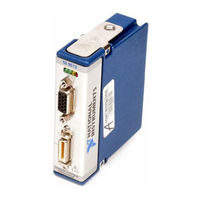
Table of Contents
Motion Control
2
Legal Information
4
Electromagnetic Compatibility Information
6
Table of Contents
7
About this Manual
9
Related Documentation
9
About the ni 951X Drive Interface Modules
10
Features
10
Hardware
10
Introduction and Installation
10
Using the ni 951X Modules in Scan Interface Mode
11
What You Need to Get Started
11
Safety Information
12
Special Conditions for Marine Applications
12
Using the ni 951X Modules in Labview FPGA Interface Mode
12
Optional Equipment
13
Hardware Overview
14
NI 951X Connections
14
NI 9512 Connections
15
NI 9514 Connections
18
NI 9516 Connections
20
NI 9512 Connectors
22
User Connectors
22
NI 9514 Connectors
25
NI 9516 Connectors
27
Axis Status
28
LED Indicators
28
Axis Fault
29
Encoder Active
29
Limit Active
29
Signal Connections
30
Command Signals
33
Power Connections
33
Step (CW)± and Direction (CCW)
33
Stepper Command Signals
33
Additional Drive Signals
35
Drive Command COM
35
Drive Command Output
35
Drive Enable
35
Servo Command Signals
35
Limit and Home Input Circuit
37
Limit and Home Inputs
37
Motion I/O Signals
37
Encoder Inputs
39
Encoder Phase A/Phase B
39
Encoder Index
40
Encoder Input Circuit
40
Position Capture Input and Position Compare Output
41
Digital I/O Signals
42
Digital Inputs
42
Digital Outputs
44
37-Pin Terminal Block Pin Assignments
46
Accessory and Cable Connections
46
NI 951X Connection Accessories
46
General Connection Recommendations
49
Limit and Digital Input Connection Recommendations
49
Signal Connection Recommendations
49
Encoder Connection Recommendations
50
Connecting a Brake Signal
51
Connecting Optional Signals
51
Motion Command Signals
52
Specifications
52
Appendix A Specifications
53
Power Requirements
56
Physical Characteristics
56
Safety Voltages
57
Safety Standards
57
Electromagnetic Compatibility
57
Online Product Certification
58
Shock and Vibration
58
Environmental Management
59
Waste Electrical and Electronic Equipment (WEEE)
59
Position Command
60
Technical Support and Professional Services
63
Advertisement
Related Products
National Instruments 9403
National Instruments 9375
National Instruments 9514
National Instruments 9516
National Instruments 9512 C Series
National Instruments 9501 C Series
National Instruments 9505E
National Instruments NI-DAQmx 9.5
National Instruments 9503
National Instruments 9512
National Instruments Categories
Control Unit
I/O Systems
Controller
Computer Hardware
Measuring Instruments
More National Instruments Manuals
Login
Sign In
OR
Sign in with Facebook
Sign in with Google
Upload manual
Upload from disk
Upload from URL