Pentair INTELLITOUCH User Manual
Control system for pool and spa
Hide thumbs
Also See for INTELLITOUCH:
- Installation manual (20 pages) ,
- Appliance upgrade manual (20 pages)

Related Manuals for Pentair INTELLITOUCH


Summary of Contents for Pentair INTELLITOUCH
- Page 1 ® INTELLITOUCH CONTROL SYSTEM FOR POOL AND SPA USER’S GUIDE IMPORTANT SAFETY INSTRUCTIONS READ AND FOLLOW ALL INSTRUCTIONS SAVE THESE INSTRUCTIONS...
- Page 2 Pentair Water Pool and Spa, Inc. Those names and brands may be the trademarks or registered trademarks of those parties or others.
-
Page 3: Table Of Contents
Digital Wireless Tablet (iTC45 Kit - P/N 520503) ................... 6 IntelliTouch ScreenLogic Interface Accessory Kits ....................6 SECTION 2 - OPERATING THE INTELLITOUCH SYSTEM ................7 Main Screen (Indoor Control Panel and MobileTouch wireless control panel) ............7 IntelliTouch Menus ..............................8 IntelliTouch Indoor Control Panel Menus ....................... - Page 4 Prepare the System for Operation ........................31 Checking the Main Load Center ........................31 Setting up the IntelliTouch System using the Indoor Control Panel or MobileTouch ........33 The Preference Screen Options ........................33 Set the System Clock ..........................34 Assigning Circuit Names (for Display 1, 2, 3, and 4) ..................
- Page 5 Calibrating Temperature Sensors ........................84 Using the Service Personnel Screen ......................... 85 Checking Firmware Version ..........................85 Manually Updating Between Indoor and Outdoor Control Panels ..............86 Erasing the System Memory ..........................87 System Worksheet Overview ..........................88 ® IntelliTouch Control System User’s Guide...
- Page 6 Troubleshooting ..............................99 Frequently Asked Questions (FAQ) ........................99 What does a ‘+3’ IntelliTouch system mean? ....................99 How Do I Setup/Configure/Program the 2-Speed Pump? ................99 Can I turn the Heater On and Change the temperature from the Spa? ............99 How do I get Solar to switch on? ........................
-
Page 7: Important Warning And Safety Instructions
WARNING - GAS HEATER: The IntelliTouch® automation control system is designed to supply high voltage (120 VAC / 240 VAC) to a gas heater and override the thermostat in the heater’s control circuit. This automation control system is intended to control gas heaters with a high temperature limit switch(s) safety circuit ONLY. - Page 8 Consult the dealer or an experienced radio/TV technician for help. General Installation Information 1. All work on the IntelliTouch® load/power center must be performed by a licensed electrician, and must conform to all national, state, and local codes. 2. Install to provide drainage of compartment for electrical components.
- Page 9 Blank Page ® IntelliTouch Control System User’s Guide...
-
Page 10: In This User's Guide
In this User’s Guide ® This User’s Guide describes how to operate the IntelliTouch pool and spa control system. This manual consists of the following sections: Section 1: IntelliTouch System Overview (page 1) Section 2: Operating the IntelliTouch System... -
Page 11: Section 1 - Intellitouch System Overview
2 Interface Kits on page 5. IntelliTouch Control System Overview An IntelliTouch control system can include five (5) to 40 high voltage relays circuits that can be used to control any combination of pumps, lights, water features. A maximum of ten (10) relays can be housed in an IntelliTouch control system Load Center or Power Center. - Page 12 /iPad Touch Interface (P/N 520500) – Includes Protocol Interface Adapter that connects ™ ® to existing Desktop or Laptop PC. This allows control of IntelliTouch pool and spa systems via PC (requires PC with an Ethernet connection, and Windows ® XP operating system).
-
Page 13: Intellitouch In Your Home
In-wall Touch Screen: A color display with Ethernet (RJ45) connector. Connects to the provided wireless router and Protocol adapter via Ethernet (RJ45) for control of IntelliTouch pool and spa systems. The in-wall Touch Screen is custom configured for IntelliTouch systems. -
Page 14: Intellitouch System Components
IntelliTouch System Components The main required components of an IntelliTouch system is a Load Center or Power Center, IntelliTouch Personality Kit, and Interface: IntelliTouch System Components The main required components of an IntelliTouch system is a Load Center or Power Center,... -
Page 15: Screenlogic Interface Kits
Expansion Kits: Models i5X (P/N 521225) and i10X (P/N 521226), offer five or ten additional Auxiliary Circuits for systems i9+3, i9+3S and i10+3D. Each IntelliTouch Expansion Kit requires a Load Center (P/N 521213) or Power Center (P/N 521214). Up to three Expansion Kits and Load or Power Centers may be added to a system, for control of up to 38 Auxiliary Circuits (40 auxiliary circuits for i10+3D). -
Page 16: Iphone/Ipad Touch Inteliface Kit (P/N 520500)
520406 Dimmer Module. Supports up to 4,000 Watts maximum load (four dimmers handling 1,000 Watts each). 520442 i-Link Home Automation Adapter Interface for IntelliTouch. 520403 Dual Heater Kit. Utilize a gas heater and heat pump. IntelliTouch Control System User’s Guide... -
Page 17: Section 2 - Operating The Intellitouch System
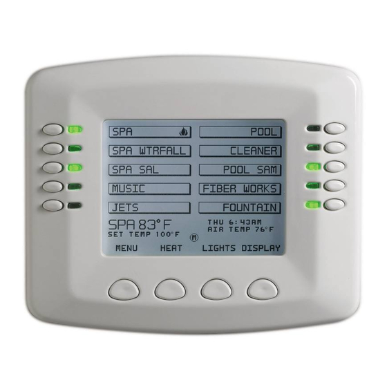
Operating the IntelliTouch System Main Screen (Indoor Control Panel and MobileTouch Wireless Control Panel) Note: For information about the KEYPAD LOCK feature, see page 80 INTELLITOUCH INDOOR CONTROL PANEL BUTTONS 56-71 HEATPUMPCOM- Pg.72 INTELLICHEM - Pg. 73 SPA OPTIONS -Pg. 77 DEGREES C/F - Pg. -
Page 18: Intellitouch Menus
IntelliTouch Menus The Indoor Control Panel menus provide system settings to automatically control the general day-to- day pool and spa operations. From the PROGRAM menus you can program equipment to switch on and off at specific times. From the SETUP and ADVANCED menus circuit functions, valves and other equipment can be setup. -
Page 19: Intellitouch Indoor Control Panel Menus
Indoor Control Panel Menus INTELLITOUCH INDOOR CONTROL PANEL BUTTONS 56-71 HEATPUMPCOM- Pg.72 INTELLICHEM - Pg. 73 SPA OPTIONS -Pg. 77 DEGREES C/F - Pg. 77 35-36 MAGIC STREAM KEYPAD LOCK Pg. 83 THUMPER - TOGGLE RESET - HOLD / STOP... -
Page 20: Heating Your Spa And Pool
Press to lower SPA temperature Press to increase SPA temperature Hi-Temp Mode for i5S and i9+3S Press to increase POOL temperature Press to lower POOL temperature Hi-Temp Mode for i5S and i9+3S Back button Set button IntelliTouch Control System User’s Guide ®... -
Page 21: Selecting The Heating System
(off) in the Heat menu. The optional iS10 Spa-Side remote, iS4 Spa Side remote or QuickTouch QT4 wireless remote can be used to switch the heater on. The IntelliTouch system supports gas, electric and solar heating systems. IntelliTouch will use the heating source that is selected. -
Page 22: Switching On Lights Manually
OFF Note: Use the SYNC button to switch ON all IntelliBrite, ® MagicStream laminar lights, SAm, SAL, or FIBERworks color changing lights to synchronize their colors when using the “Color Swim” lighting feature. IntelliTouch Control System User’s Guide ®... -
Page 23: Special Lighting Features
COLOR SET OFF. LIGHTS Use the ALL OFF button ALL OFF SYNC SAVE ALL ON Switch on all color changing lights to synchronize colors Switches all SAm, SAL and Fiberworks lights ON and Synchronizes lights IntelliTouch Control System User’s Guide ®... -
Page 24: Dimming Lights
Spa or Pool button to switch the circuit on. From the “Program” screen, you can schedule IntelliTouch to automatically run equipment like pool filtration or lights. Any circuit (auxiliary, feature, or macro) can be scheduled to switch on and off at a specific time and on a any day(s) of the week. -
Page 25: Smart Start (Setting Up Sam, Sal And Intellibrite Lights)
SS_Yes and SS_No. Select SS_Yes to automatically begin changing colors when the light circuit is switch on. 4. Setup each light circuit as described above in steps 2 - 5. IntelliTouch Control System User’s Guide ®... -
Page 26: Using The Once Only Timer
Using the Once Only Timer The “Once Only” programming feature enables IntelliTouch to automatically switch equipment on for one time only. For example, you can set to have the spa and heater switch on before you get home from work for one evening. Unlike a regular scheduled program, the “Once Only” program does not repeat. -
Page 27: Setting The Egg Timer Function
(1) program for the selected circuit. 7. Press the Back button to return to the SPA, POOL and AUX equipment selection screen to program other equipment. 8. Press the Exit button to return to the main screen. IntelliTouch Control System User’s Guide ®... -
Page 28: Is10 Spa-Side Remote Controller
As many as four SpaCommand remotes can be installed in i5+3, i5S+3, i7+3, i9+3, i9+3S, and i10+3D systems. The remote controller is for use with the IntelliTouch systems at the water’s edge. Five (5) in-line buttons control up to ten (10) system functions numbered one through five from left to right as shown (if the system allows). -
Page 29: Is4 Spa-Side Remote Controller
Panel. It has an operating range of up to 300 ft. from the MobileTouch transceiver antenna (line of sight) which is typically located near the IntelliTouch load center. The optimum wireless transmit and receive range may be affected by physical obstructions, (especially those containing metal), weather conditions, and geographical features. -
Page 30: Charging The Mobiletouch Wireless Controller
The range of the MobileTouch wireless controller can be up to 300 feet from its transceiver antenna (line of sight). The transceiver antenna is typically located outside near the IntelliTouch Load Center. The device can be used all day at full power with a complete battery charge (3 to 4 hours). -
Page 31: Quicktouch Wireless Qt4 Remote Controller
2 lbs. of pure chlorine per 24 hours of continuous pool pump run time. The IC60 cell uses a total of 15 blades (three terminal and twelve bi-polar blades). IntelliChlor “dummy” bypass cell (P/N 520588): Recommended for new pool start-up. Note: For IntelliChlor setup information, see “Chlorine Generator,” on page 54. IntelliTouch Control System User’s Guide ®... -
Page 32: Intelliflo Vf 3050 Variable Flow Pump (Accessory)
The IntelliFlo VSF+SVRS variable speed and frequency (RPM/GPM) pump offers the same basic feature set as the IntelliFlo VS 3050 pump with additional Safety Vacuum Release System (SVRS) and flow control (GPM) functionality. Note: For IntelliFlo VSF+SVRS setup information, see page 65. IntelliFlo ® Pump IntelliTouch Control System User’s Guide ®... -
Page 33: Section 3 - Preparing The System For Initial Start-Up
Section 3 Preparing the System for Initial Start-up Setting up the IntelliTouch System Use the following recommended steps to configure the IntelliTouch system using the Indoor Control Panel or MobileTouch wireless controller. 1. Main screen preference settings (page 33) Setup the Indoor Control Panel main screen. Set the system clock and what circuit names you wish to display on the main screen. - Page 34 7. Setting up additional equipment (pages 53) Configure the IntelliTouch system what special equipment the system may have installed. • Is there an IntelliFlo pump installed? • Is there an UltraTemp heat pump installed? • Is there an IntelliChlor salt chlorine generator installed? •...
-
Page 35: Wired Controllers (Automatically Enabled)
Wired Controllers (Automatically Enabled) When powered up for the first time, the IntelliTouch system will automatically enable one each of the following wired controllers: • Outdoor Control Panel (located in the main Load Center or Power Center) • Indoor Control Panel (wired to the Personality board in Load Center). Note: Additional Indoor Control Panels must be manually assignment. -
Page 36: Manually Enabling Expansion Centers
Note: For information about how the IntelliTouch automatically enables wired controllers, refer to the “Automatically Enabled Wired Controllers,’’ page 25. Up to three (3) additional Expansion Centers can be installed in the IntelliTouch system. The IntelliTouch system automatically assigns the “main” Load Center or Power Center as number 1, and other additional Expansion Centers as number 2, 3, or 4. -
Page 37: Assigning Additional Expansion Centers
7. After each Expansion Center is enabled, press Reset on the Outdoor Control Panel. Wait until the red Auto and Pool LED is lit. The system is ready for normal operation. Power Center Additional Main IntelliTouch Additional (i5x or i10x), Expansion... -
Page 38: Setting Up The Mobiletouch Wireless Controller
ADVANCED 4. From the MobileTouch controller Advanced screen, press the lower buttons 2 and 4 at the same time. The Service Personnel screen will be displayed. Press button 2 and 4 at the same time to access the Service Personnel screen IntelliTouch Control System User’s Guide ®... - Page 39 ADDRESS LOCK AUTO” - Press AUTO to lock on the address. If MobileTouch does not connect then use the MAN (manual) mode. You will notice on the IntelliTouch outdoor control panel there are three System Control LEDs flashing on and off. There are also two other LEDs going on and off. Watch these LEDs and you will see a pause, followed by one of the AUX 1 - 8 or Heater or solar LEDs flash on, then it goes off and a second LED will flash on.
-
Page 40: Adding A Spacommand Spa-Side Remote
IS1. Other additional iS10 remotes need to be manually assigned. To assign additional SpaCommand remotes as iS2, iS3, or iS4: 1. On the IntelliTouch Outdoor Control Panel, press the Reset button, then press the 1 button. The three (3) System Control LEDs will start flashing. -
Page 41: Prepare The System For Operation
Note: for i5+3, i7+3, or i9+3 systems, go to step 5. If you are working with the i5S+3, i9+3S, or i10+3D systems, skip step 5 and go to step 6. The IntelliTouch system model ID is located on the front of the Indoor Control Panel below the low voltage circuit breakers. - Page 42 For details about adding multiple Expansion Centers and controllers, see “Assigning Additional Expansion Centers” on page 27. V” Valve button ‘ “F” Filter Pump button AUX circuits buttons/LEDs IntelliTouch system model Label location for AUX circuit name number IntelliTouch Control System User’s Guide ®...
-
Page 43: Setting Up The Intellitouch System Using The Indoor Control Panel Or Mobiletouch
Setting up the IntelliTouch System using the Indoor Control Panel or MobileTouch The following describes how to configure and set up the IntelliTouch system using the Indoor Control Panel or MobileTouch wireless control panel. The Preference Screen Options From the Preference screen you can change various screen options. -
Page 44: Set The System Clock
Set the System Clock It’s important to set the IntelliTouch system clock to the current time and date to ensure all automatic pool functions to work correctly. Getting There MENU SETUP CLOCK To set the system clock, go to the Clock screen. -
Page 45: Selecting Display Screen 1, 2, 3, Or 4
3. Use the Up and Down buttons at the bottom of the screen to scroll through the alphabetical list of preset equipment names. Choose the equipment name that matches the label name for button number 1 on the Load Center Outdoor Control Panel. IntelliTouch Control System User’s Guide ®... -
Page 46: Selecting The Display Screens
For more information, see page 7. EDGE PUMP ALL LIGHTS CLEANERS CLEANERS WATER FALL MON 4:32AM AIR TEMP 92˚ MENU HEAT LIGHTS DISPLAY Display button Main screen Display #1, #2, #3, or #4 screen Feature circuits screen IntelliTouch Control System User’s Guide ®... -
Page 47: Intellitouch Circuit Names
IntelliTouch Circuit Names (NOT USED) Custom Names (11 characters maximum) AERATOR AIR BLOWER OZONATOR AUX 1 PATH LIGHTS USER NAME 01 ____________________ AUX 2 POOL SAM 3 SECURITY LT AUX 3 USER NAME 02 ____________________ SLIDE AUX 4 AUX 5... -
Page 48: Creating Custom Names For Auxiliary Circuits
Move cursor left Move cursor right Scroll forward through characters Scroll back through characters Move cursor up Move cursor down Move cursor left Move cursor right Delete and Backspace button Select button Display Clear button button IntelliTouch Control System User’s Guide ®... -
Page 49: Assign Circuit Functions And Freeze Protection
Select the Feature circuit name to assign a function to it. Use ALL LIGHTS CLEANERS CLEANERS EDGE PUMP this button to toggle between the Feature circuit screen and the WATER FALL Circuit screen. MON 4:32AM AIR TEMP 92˚ LIGHTS DISPLAY MENU HEAT IntelliTouch Control System User’s Guide ®... - Page 50 4. Press the SAVE button when finished. 5. Press the BACK button to return to the Circuits screen and repeat steps 1 through 4 to assign functions to other circuits. 6. Press EXIT button to return to the Main screen. IntelliTouch Control System User’s Guide ®...
-
Page 51: Special Functions For Circuits
“GENERIC” circuit function, not the “Floor Cleaner” function. Assigning the “Generic” circuit function ensures that the pump will not ramp up and down every 20 minutes. IntelliTouch Control System User’s Guide ®... -
Page 52: Setting Up Lighting Options (Color Swim And Color Set)
(AUX 1), then assign the circuit name for that light circuit. The light circuit name will appear on the main screen. Each light (SAM or SAL) must also be assigned a circuit function. If the circuit function has been assigned, start at Step 5 (see next page). IntelliTouch Control System User’s Guide ®... - Page 53 7. Press the button next to DISPLAY 1. Display 1 is the main indoor control panel. If there are additional IntelliTouch Expansion Centers installed, Display 2, Display 3, and Display 4 will be displayed. Select which indoor control panel to configure. From this screen you can also configure Feature circuits.
- Page 54 SPA SAL Press this button to configure “Pool Sam 1” light circuit for “SPA” NONE POOL SAM 1 Available light circuit for “POOL” NONE NONE View/configure next NEXT GROUP six light circuits LIGHTS/CONFIG-SELECTION BACK EXIT IntelliTouch Control System User’s Guide ®...
- Page 55 SAVE ALL ON ALL OFF SYNC 19. Press Back to view the Lights screen. “SPA SAL” on and off switch is now assigned to the AUX 1 button. IntelliTouch Control System User’s Guide ®...
-
Page 56: Setting Up Intellibrite Led Lights
3. Press the SAVE button on the bottom of the screen. Press the EXIT button to return to the main screen. MENU/SETUP/ADV/FUNC/AUX 1 EXIT BACK SAVE 4. Proceed to Step 5. IntelliTouch Control System User’s Guide ®... - Page 57 POOL SAM 1 NEXT Select the color PREV WHITE NEXT Select the light PREV 1ST POSITION NEXT Color Swim: Set the PREV DELAY 5 SECS NEXT delay time between LIGHTS/CONFIG/POOL SAM 1 SAVE EXIT IntelliTouch Control System User’s Guide ®...
-
Page 58: Selecting Intellibrite Modes
(6) seconds followed by the “COLOR SWIM” feature selection. If the light was previously on, after pressing the SWIM button, the previously selected color will momentarily illuminate, no illumination will occur for approximately six (6) seconds followed by the “COLOR SWIM” feature selection. IntelliTouch Control System User’s Guide ®... -
Page 59: Feature: Color Set
Use the “Hold” and “Recall” feature to capture and save the selected color and recall it at a later time. Note: After pressing the HOLD or RECALL button, no illumination will occur for up to 10 seconds, then a white light will momentarily illuminate, followed by the saved color. IntelliTouch Control System User’s Guide ®... -
Page 60: Setting Up Magicstream Laminars
4. Proceed to Step 5. AUX 4 PREV MAGICSTREAM NEXT AUX 1 AUX 5 ON WITH FREEZE AUX 3 AUX 6 AUX 2 AUX 7 AUX 4 AUX 8 MENU/SETUP/ADV/FUNC/AUX 1 MENU/SETUP/ADV/FUNCTION/SELECT EXIT BACK SAVE BACK EXIT IntelliTouch Control System User’s Guide ®... - Page 61 POOL LIGHT POOL LAMINAR 2 buttons ntelliBrite button for INTELLIBRITE MAGICSTREAM NEXT GROUP CONFIGURE Color and Mode Light LIGHTS show ALL OFF SYNC SAVE ALL ON Lights screen using IntelliBrite lights and MagicStream laminars IntelliTouch Control System User’s Guide ®...
-
Page 62: Using The Magicstream Laminar Features
THUMPER SPA LIGHT TOGGLE MODE POOL LAMINAR 1 circuit buttons HOLD / STOP POOL LIGHT POOL LAMINAR 2 RESET INTELLIBRITE MAGICSTREAM NEXT GROUP CONFIGURE LIGHTS LIGHTS/MAGICSTREAM SAVE ALL ON ALL OFF SYNC BACK EXIT IntelliTouch Control System User’s Guide ®... -
Page 63: Setting Up Equipment (From The Equipment Screen)
Setting up Equipment (from the Equipment Screen) If any special equipment is attached to the IntelliTouch Load Center, you need to setup IntelliTouch to recognize that equipment. From the Equipment screen you can setup: PRIORITY SOLAR CHLORINATOR 2-SPEED PMP •... -
Page 64: Chlorine Generator
Adjusting the Chlorine Output Level In an effort to prevent over chlorination of the spa, the IntelliTouch system will automatically drop the chlorine output levels to 1/20th of the current pool output when the spa is switched on. For example, if the pool output level is set to 60%, when the spa is switched on, the chlorination level is reduced to 3%. -
Page 65: Super Chlorinate The Pool Water
OK - NO ERRORS Note: For information about wiring a salt chlorine generator WATER SALT LEVEL 2900 PPM to the IntelliTouch system , see “Wiring IntelliTouch to a Salt HOURS REMAINING 22 @ 100% Chlorine Generator,” on page 112. CONTROL ENABLED... -
Page 66: Intelliflo Vf 3050, Vs 3050 And Vsf+Svrs Pump Setup
How many pumps will IntelliTouch support? IntelliTouch can support up to eight IntelliFlo VF and four IntelliFlo VS pumps in any combination with up to eight GPMs or RPMs per pump. For example pumps can be connected to IntelliTouch as follows: •... -
Page 67: Intelliflo Menu Options
IntelliTouch will restart the cleaner delay, as if it was just starting to insure water in the plumbing. IntelliTouch requires a bit more delay since the circulation pump may be on any address, e.g. #5, if there are four IntelliFlo VS pumps at 1 -4, and a VF at #5. So by default no pump is assigned. When you go into the menu “Circuit Functions”... -
Page 68: Intelliflo Vf 3050 Pump Setup
The selected circuit name must also be assigned a circuit function. For details about assigning a circuit function and a feature circuit, see pages 39 and 76. Press Press this IFLO VF 3050 POOL this PENTAIR IFLO VF 3050 button to select IFLO VS 3050 IFLO VF 3050 #1 POOL button to the IntelliFlo... -
Page 69: Filtering Parameters
1. From the main pump screen, press the left side button next to the select IntelliFlo pump. 2. On the next screen, press the left side button next to SET PARAMETERS then on the following screen select FILTERING PARAMETERS. PENTAIR IFLO VF 3050 FILTERING PARAMETERS IFLO VF 3050 #1... -
Page 70: Priming Parameters
If the strainer has been removed for cleaning and a sub- BACK SAVE EXIT stantial amount of air is in the system it should prime in about 60 to 90 seconds on the average, however, all systems will be different. Save button IntelliTouch Control System User’s Guide ®... -
Page 71: Backwash Parameters
When the pump detects that the filter differential pressure (10 PSI difference) has increased and is now at the “Clean Filter” pressure, IntelliTouch displays an alert message. This means that the filter must be cleaned (backwashed) to reduce the pressure. To do this, the pump must be stopped and the IntelliTouch outdoor control panel must be in “Service”... -
Page 72: Vacuum Parameters
Use the Vacuum mode to clean the pool manually. To operate the pump in Vacuum mode, place the IntelliTouch outdoor control panel in “Service Mode,” and stop the IntelliFlo pump. The pool service person can then press the Vacuum button on the IntelliFlo pump. The pump would operate at the preset Vacuum parameters, then the blockage alert parameter would be cleared and the pump will stop. -
Page 73: Assign Custom Flows
NONE 0 GPM Press this NONE 0 GPM button go to four NEXT PAGE additional circuits/ GPM settings MENU/SETP/EQUIP/INTELLIFLO/ASSIGN BACK SAVE PREV EXIT Save button Prev and Next buttons (use to adjust pump speed) IntelliTouch Control System User’s Guide ®... -
Page 74: Intelliflo Status Screen
To view the current pump status: 1. Press MENU > SETUP > EQUIPMENT > INTELLIFLO >. Press the left side button next to the IntelliFlo VF 3050 pump. PENTAIR IFLO VF 3050 IFLO VF 3050 2. On the next screen, press the left side button next to... -
Page 75: Intelliflo Vs 3050 And Vsf+Svrs Pump Setup
Before assigning a pump address in the IntelliTouch indoor control panel, first set the address on the pump itself. If there is only one pump, it is always seen as pump #1 by IntelliTouch. In this case you do not need to set the pump address. When using multiple IntelliFlo VS 3050 pumps with IntelliTouch you need to assign an address to each pump. -
Page 76: Setting Up An Intelliflo Vs 3050 And Vsf+Svrs Pump From Equipment Screen
IntelliTouch, the default address is always pump #1. When using multiple IntelliFlo VS 3050 and VSF +SVRS pumps with IntelliTouch assign an address to each pump. For IntelliFlo VS 3050 set the address to #1, #2, #3 or #4. For IntelliFlo VSF +SVRS set the address from #1-#8. The address set at the pump must match the IntelliFlo pump number selected in the “Equipment”... -
Page 77: Priming Parameters (Intelliflo Vs 3050)
0 minutes, the priming speed will be used from that period (assuming the priming speed is greater than the speed being requested). Getting There MENU SETUP EQUIPMENT INTELLIFLO PENTAIR IFLO VS 3050 IFLO VF 3050 POOL IFLO VS 3050... -
Page 78: Assign Custom Speeds (Rpm) Intelliflo Vs 3050)
Note: An IntelliFlo VS 3050 pump can only be assigned as pump #1, #2, #3, or #4. 2. On the next screen, press the left side button next to ASSIGN CUSTOM SPEEDS. PENTAIR IFLO VS 3050 IFLO VF 3050... -
Page 79: Assign Custom Speeds (Rpm/Gpm) Intelliflo Vsf+Svrs
1. From the main pump screen, press the left side button next to the selected IFLO VSF+SVRS pump. Note: The IntelliFlo VSF+SVRS pump can assigned as pump #1 - #8. 2. On the next screen, press the left side button next to ASSIGN CUSTOM SPEEDS/FLOWS. Press this PENTAIR IFLO VSF+SVRS IFLO VF 3050 POOL button to... - Page 80 PSI setting. Press the DOWN and UP buttons to adjust the PSI setting. Press the SAVE button to save the setting. Press this button to PENTAIR IFLO VSF+SVRS #3 PENTAIR IFLO VSF+SVRS #3 change Press this...
-
Page 81: Intelliflo Vs 3050 And Intelliflo Vsf+Svrs4 Status Screen
2. On the next screen, press the left side button next to INTELLIFLO STATUS to access the status screen. This screen displays the selected IntelliFlo pump and address Press this PENTAIR IFLO VS 3050 button to IFLO VS 3050 PRIMING PARAMETERS... -
Page 82: Setting Up An Ultratemp Heat Pump
Connection from the Pentair UltraTemp heat pump to the IntelliTouch system is via an RS-485 communication cable to a COM PORT on the IntelliTouch Personality circuit board. See page 112 for UltraTemp to IntelliTouch COM port wiring information. -
Page 83: Setting Up Intellichem Water Chemistry Controller
Setting up IntelliChem Water Chemistry Controller IntelliChem screen IntelliChem provides the IntelliTouch system with continual analysis of your swimming pool water sanitation and pH levels, providing real-time status information to dispense the proper amount of muriatic acid (pH reducer) and chlorine or bromine for the correct sanitization and pH balance. -
Page 84: Setup Solar Equipment And Heat Pump Option
50° F, at which point the heat pump will switch off and the heater will switch on and take over. The air temperature is detected by the solar temperature sensor located on Press to scroll the IntelliTouch load center. The air temperature is not through SPA and select adjustable. -
Page 85: Setting Up A 2-Speed Pump
“Fireman Switch.” for example, If you are in the spa, and you switch it off. The IntelliTouch will return the valves to “Pool” mode position. If the pool is running a cycle, or the Fireman switch (Master Spa/Pool Delay) is enabled, colder water from the pool would be pumped into the spa as the valves turn. -
Page 86: Master Spa/Pool And Delays For Valves
For convenience, on a one time basis, the DELAY CANCEL feature will cancel the following safety delays which can be set up in the IntelliTouch system. Please note there is generally not a need to cancel any of these delays except for servicing or testing the system. -
Page 87: Spa Options
To change the temperature settings go to the Degrees C/F screen. 1. Press the left or right side button next to Degrees Displayed In to select C (Celsius) or F (Fahrenheit). 2. Press the Save button. 3. Press the Exit button to return to the main screen. IntelliTouch Control System User’s Guide ®... -
Page 88: Configuring Valve Actuators (Controlled By Aux Or Feature Circuit)
Configuring Valve Actuators (Controlled by AUX or Feature Circuit) All IntelliTouch systems can drive two auxiliary valve actuators (A and B) for applications such as solar heating and water features. With the addition of the Valve Module (P/N 520285), installed in the Load Center or Power Center, the system will accommodate up to three additional actuators (C, D, and E). -
Page 89: Feature Circuits
Feature circuit screen is displayed. The F icon MON 4:32AM AIR TEMP 92˚ located in the middle lower part of the screen indicates that Feature LIGHTS DISPLAY MENU HEAT circuits screen is selected. Feature circuits screen IntelliTouch Control System User’s Guide ®... -
Page 90: Creating A Macro Circuit
The Macro circuit name (or custom name) can be added to the main list of “IntelliTouch circuit names” (see page 37). A Macro circuit also has the capability to switch a circuit off. For example, a Macro circuit named “SPA PARTY,” if you wanted a spa fountain not to be on when spa is on (because it could put cold water in the spa), it can be set up in the Macro to automatically switch off when “SPA PARTY”... -
Page 91: Configuring Remote Control Button Circuits (Is4, Spacommand, Spa Side Remtoe, Qt4 Quicktouch, And Phone Remote)
IntelliFlo VF 3050, VS 3050 and VSF+SVRS pump speeds. Up to two iS4 remotes, and four iS10 and SpaCommand remotes can be connected to an IntelliTouch system. To assign a circuits to spa-side remote buttons: iS4 spa side remote 1. Press the button next to CONFIGURE iS4’S or... -
Page 92: Setting Up The Remote Control Telephone Feature
HEAT.” This allows the heater to always switch on whenever the spa is switched on via the telephone. For more information, see page 77. 4. Press the Save button to save the setting and return to the remotes screen. IntelliTouch Control System User’s Guide ®... -
Page 93: Disable/Enable Spa-Side Remote
REMOTE ENABLED. Remote is now on. 2. Press the Back button to return to the main screen. Keypad Lock If required, the IntelliTouch indoor control panel and MobileTouch wireless control panel can be passcode protected so that system settings and operations cannot be accessed. -
Page 94: Section 4 - Service And Maintenance
Section 4 Service and Maintenance Calibrating Temperature Sensors The IntelliTouch system includes two temperature sensors (10 kΩ) for water and ambient air temperature. You can add a third sensor for controlling solar heating systems. Note: The i10+3D system includes three sensors. -
Page 95: Using The Service Personnel Screen
This feature is available from the Service Personnel Checking Firmware Version The IntelliTouch factory installed operating system software is known as firmware. There is a different firmware program loaded on the controllers (indoor control panel and MobileTouch) and the outdoor control panels. -
Page 96: Manually Updating Between Indoor And Outdoor Control Panels
Manually Updating Between Indoor and Outdoor Control Panels When the IntelliTouch system configuration settings are changed, or a new component is added, the updated information is automatically communicated to all of the control panels. Configuration settings reside in all the controllers and the outdoor control panel. This feature provides system backup information in the event one of the controllers or control panels is not operational. -
Page 97: Erasing The System Memory
Erasing the System Memory IntelliTouch system circuit settings, equipment setup configuration information and screen display information is stored in the main Outdoor Control Panel and the Indoor Control Panel and MobileTouch wireless control panel. The current system configuration information automatically downloads from programmed control panels to update non-programmed control panels in case of accidental memory loss. -
Page 98: System Worksheet Overview
Spa-Side remote. The top buttons of the main screen are dedicated for Spa and Pool modes, however the lower buttons numbered downward may be configured to display any circuit. Note: Keep the homeowner worksheets for future reference. IntelliTouch Control System User’s Guide ®... - Page 99 WORKSHEET FOR SHARED EQUIPMENT SYSTEMS i5+3, i7+3, i9+3 (Sheet 1 of 2) IntelliTouch Control System User’s Guide ®...
- Page 100 WORKSHEET FOR SHARED EQUIPMENT SYSTEMS i5+3, i7+3, i9+3 (Sheet 2 of 2) IntelliTouch Control System User’s Guide ®...
- Page 101 WORKSHEET FOR SINGLE BODY SYSTEMS i5S+3, i9+3S (Sheet 1 of 2) IntelliTouch Control System User’s Guide ®...
- Page 102 WORKSHEET FOR SINGLE BODY SYSTEMS i5S+3, i9+3S (Sheet 2 of 2) IntelliTouch Control System User’s Guide ®...
- Page 103 WORKSHEET FOR DUAL EQUIPMENT SYSTEMS i10+3D (Sheet 1 of 2) IntelliTouch Control System User’s Guide ®...
- Page 104 WORKSHEET FOR DUAL EQUIPMENT SYSTEMS i10+3D (Sheet 2 of 2) IntelliTouch Control System User’s Guide ®...
-
Page 105: Main Outdoor Control Panel
Load Center or Power Center. The Outdoor Control Panel includes, control buttons for pumps, filters, and heater, red status lights, and a Reset button. The IntelliTouch Personality board defines the type of equipment installed. The Outdoor Control Panel can be used to override the Indoor Control Panel functions for pool service and for equipment set up. -
Page 106: Shared Equipment Systems Model I5+3, I7+3, I9+3
IntelliTouch Outdoor Control Panels For IntelliTouch system wiring diagrams, see pages 41-43. Shared Equipment Systems Model i5+3, i7+3, i9+3 Single Body Systems Model i5+3S, i9+3S Operates the same as i5+3, i9+3, except no valve controls. Dual Body Dual Equipment System Model i10+3D The i10+3D is designed to operate two sets of pool equipment. -
Page 107: Erasing Outdoor Contrl Panel Memory (Factory Default)
“AUTO” and “POOL” modes before resuming operation. 7 button Reset button LEDs (System Control) (i5, i10x) 5 button (i5+3, i7+3, i9+3, i5S+3, i9+3S, i10+3D) Main Outdoor Control Panel in the Load Center or Power Center IntelliTouch Control System User’s Guide ®... -
Page 108: Section 5 - Troubleshooting
The following information describes a basic system start-up procedure. Before switching on the power to the IntelliTouch load center, first affix the auxiliary relay labels to the appropriate buttons on the Outdoor Control Panel. If necessary, write the function on the control panel. -
Page 109: Troubleshooting
This section provides information to help you resolve any problems that may occur during installing or using the IntelliTouch system. If by following the recommended actions you are still unable to resolve the problems please contact Technical Support, see page vii. -
Page 110: What Are Color Swim And Color Set
5. The procedure is identical to Step 2 above. Plug into the COM port on the Personality board in the Load Center or Power Center. Again, several different things may happen. Check all the relevant sections to avoid any problems. IntelliTouch Control System User’s Guide ®... -
Page 111: Fixing Mismatched System Personalities
2. A controller’s memory is erased while unplugged from the system. 3. The IntelliTouch system personality (i9+3, i10+3D etc.) was changed. If this problem occurs a mismatched system personality message screen may be displayed. Press the NEXT button to update the controller to match the system personality. -
Page 112: System Problem Diagnosis
If this occurs contact tech support for replacement order) PCBs. This is most effectively determined by using a Defective Indoor Con- spare Indoor controller or service man’s panel. trol Panel Contact tech support for replacement PCB IntelliTouch Control System User’s Guide ®... -
Page 113: Problem: Indoor And Outdoor Control Panels Work, But Is4 Fails To Operate
VANCED/SPA, RF, & PHONE REMOTES’Select ration or circuit to ‘CONFIGURE iS4’s’Insure the iS4 in question has switch assignment or the expected circuit assignments, and is not as- defective wiring. signed to unused circuits. Defective iS4 Replace defective iS4 IntelliTouch Control System User’s Guide ®... -
Page 114: Problem: Indoor And Outdoor Control Panels Work, But Is10 Fails To Operate
IS10 is not correctly See page 80 to manually enable the iS10. enabled Replace defective iS10. Contact Technnical Sup- Defective iS10 port. IntelliTouch Control System User’s Guide ®... -
Page 115: Problem: The Mobile Control Panel Will Not Work, Or Will Not Work Dependably
Transceiver attached This is rare, and normall, only the green wire The MobileTouch fails to to the Load Center ot would cause this problem. Verify Connection. operate dependably. Power Center is not correctly wired. IntelliTouch Control System User’s Guide ®... -
Page 116: Problem: The Quick Touch Remote Will Not Work, Or Will Not Work Dependably
Problem: The Quick Touch remote will not work, or will not work dependably. Symptom Possible Cause Solution IntelliTouch Load Ensure power is being supplied and that the Center or Power power center operates correctly without the re- Center does not have ceiver installed. - Page 117 OFF, or range is greatly in close proximity to reduced when equipment is the receiver. running IntelliTouch Control System User’s Guide ®...
-
Page 118: Intelliflo Alerts And Warnings
Anti-freezing: When active, the motor will run at 1000 rpm for 60 minutes. Only active in Filter and Manual modes. Note: The IntelliFlo’s internal anti-freeze protection is disabled when connected to an IntelliTouch system. Freeze protection is provided by selecting YES at the ON WITH FREEZE portion of the IntelliTouch’s appropriate circuit function menu. To re-enable the IntelliFlo’s internal anti-freeze protection, the power to the drive must be cycled... -
Page 119: Intelliflo Vs 3050 And Intelliflo Vsf+Svrs Warning And Alarm Conditions
3. Replace drive. 1. Rapid switching between speeds Excessive volt- Over voltage Alarm can cause excessive voltages age on drive buss on the drive’s DC buss. 2. Ensure proper supply voltage. IntelliTouch Control System User’s Guide ®... -
Page 120: Intellitouch Power Center Wiring Diagram
IntelliTouch System Wiring Diagram (i5+3, i7+3, i9+3) IntelliTouch Load Center System Wiring Diagram IntelliTouch Control System User’s Guide ®... -
Page 121: Intellitouch Load Center Wiring Diagram
IntelliTouch Control System Wiring Diagram (i10+3D, i5+3S, i9+3S and i10+3D) IntelliTouch Control System User’s Guide ®... -
Page 122: Wiring Intellitouch To A Salt Chlorine Generator
IMPORTANT: On the UltraTemp AutoSet board ONLY CONNECT PIN 3 (YELLOW) and PIN 2 (GREEN) to the IntelliTouch COM port pins YELLOW and GREEN respectively. Do not connect pin 1 or pin 4 on the AutoSet board or the IntelliTouch Personality board. These pins are not used. -
Page 123: Glossary
Load Center: Metal enclosure with power relays, transformer, and circuit breakers. The Load Center is Installed prior to Personality Kit installation. Used for distributing power for controlling IntelliTouch Systems. Also known as the “sub-panel.” Low Voltage Compartment: Top compartment of Load Center or Power Center for all low voltage wiring. - Page 124 Transceiver: Special printed circuit board that can send and receive radio frequency (wireless) transmissions. QuickTouch QT4: Provides switching of up to four remote control circuits from a wireless Hand-held Remote. Valve Module: Accessory PCB (P/N 520285) to increase auxiliary actuator outputs from two to five. IntelliTouch Control System User’s Guide ®...
-
Page 125: How To Backwash Your Filter
To BACKWASH a sand filter with a multiport valve Note: If you are using an IntelliFlo pump with IntelliTouch, first set IntelliTouch in “SERVICE” mode (press the “System Control” button adn select “Service” on the IntelliTouch outdoor control panel. - Page 126 NOTES...
- Page 127 NOTES SAVE THESE INSTRUCTIONS...
- Page 128 1620 HAWKINS AVE., SANFORD, NC 27330 • (919) 566-8000 10951 WEST LOS ANGELES AVE., MOORPARK, CA 93021 • (805) 553-5000 WWW.PENTAIRPOOL.COM © 2011 Pentair Water Pool and Spa, Inc. All rights reserved. *521075* P/N 521075 REV. A 05/31/11...
Need help?
Do you have a question about the INTELLITOUCH and is the answer not in the manual?
Questions and answers
My spa temperature is reading 255!… I have recently changed the temperature sensor in my Jandy pool heater..it worked for about 1 week but the temperature readings inside were not right…
A Pentair IntelliTouch spa temperature reading of 255 after changing the temperature sensor in a Jandy pool heater could be caused by a faulty or improperly connected temperature sensor. This value often indicates an open circuit or that the sensor is not being detected by the system. Ensure the sensor is properly mounted, wired correctly, and compatible with the IntelliTouch system.
This answer is automatically generated