Pentair EASYTOUCH PL4 Installation Manual
For pool and spa
Hide thumbs
Also See for EASYTOUCH PL4:
- User manual (80 pages) ,
- Installation manual (48 pages) ,
- Appliance upgrade manual (20 pages)
Table of Contents
Advertisement
Quick Links
- 1 Easytouch Pl4/Psl4 Control System Power Center Installation Overview
- 2 Installing Conduit and Conductors to the Power Center
- 3 Electrical Wiring High Voltage Connections
- 4 Installing Valve Actuators
- 5 Wiring Pentair Intelliflo Pumps
- 6 Easytouch Pl4/Psl4 Control System Indoor Control Panel Installation
- Download this manual
Advertisement
Table of Contents

Related Manuals for Pentair EASYTOUCH PL4


Summary of Contents for Pentair EASYTOUCH PL4
- Page 1 EASYTOUCH PL4/PSL4 CONTROL SYSTEM ® FOR POOL AND SPA INSTALLATION GUIDE IMPORTANT SAFETY INSTRUCTIONS READ AND FOLLOW ALL INSTRUCTIONS SAVE THESE INSTRUCTIONS...
- Page 2 Customer Service / Technical Support USA Phone: (800) 831-7133 8 A.M. to 7:30 P.M. (ET) Fax: (805) 284-4151 Web sites visit www.pentairpool.com and staritepool.com P/N 522460 Rev. A 7/2014...
-
Page 3: Table Of Contents
Accessories: ............................. 34 EasyTouch PL4/PSL4 Control System Indoor Control Panel Installation ........... 21 EasyTouch PL4/PSL4 Control System QuickTouch II Wireless Controller Installation ......25 EasyTouch PL4/PSL4 Control System Outdoor Control Panel Installation ..........28 EasyTouch PL4/PSL4 Control System Circuit Board Connections ............30 EasyTouch PL4/PSL4 Control System Wiring Diagram ................ -
Page 4: Important Warning And Safety Instructions
WARNINGS AND ALL INSTRUCTIONS BEFORE USING THIS PRODUCT. This Guide provides installation and operation instructions for the product. Consult Pentair Water Pool and Spa, Inc. (“Pentair”) with any questions regarding this product. This product is intended for use in swimming pool applications only. - Page 5 IMPORTANT WARNING AND SAFETY INSTRUCTIONS Water temperature in excess of 100° F (37.7° C) may be hazardous to your health. Prolonged immersion in hot water may induce hyperthermia. Hyperthermia occurs when the internal temperature of the body reaches a level several degrees above normal body temperature of 98.6°...
- Page 6 IMPORTANT WARNING AND SAFETY INSTRUCTIONS FCC Standard - 47 CFR Part 15, Subpart C (Section 15.247). This version is limited to chapter 1 to chapter 11 by specified firmware controlled in the U.S.A. Instruction to user - This equipment has been tested and found to comply with the limits for a Class B digital device, pursuant to Part 15 of the FCC Rules.
-
Page 7: General Installation Information
IMPORTANT WARNING AND SAFETY INSTRUCTIONS General Installation Information 1. All work must be performed by a licensed electrician, and must conform to all national, state, and local codes. 2. Install to provide drainage of compartment for electrical components. 3. If this system is used to control underwater lighting fixtures, a ground-fault interrupter (GFCI) must be provided for these fixtures. - Page 8 ® EasyTouch PL4/PSL4 Control System Model Part Numbers EasyTouch PL4/PSL4 CONTROL SYSTEM MODEL PART NUMBERS 522352 PL4 - Single Body / Base System (no Indoor Control Panel, no actuators) 522353 PL4 - Single Body / ScreenLogic ® Bundle (no Indoor Control Panel, no actuators)
-
Page 9: Introduction
EasyTouch Pool and Spa Lite 4 Circuit (PSL4 - Four circuit pool and spa shared equipment system) Your EasyTouch PL4/PSL4 Control System can control high voltage (120 VAC / 240 VAC) equipment, automatic valve actuators, pumps, lighting, a conventional heater or a solar heating ®... - Page 10 Touch Interface (P/N 520500) – Includes Protocol Interface Adapter that ™ /iPad ® connects to existing Desktop or Laptop PC. This allows control of EasyTouch PL4/PSL4 XP/Win7/Win8 ® Control System via PC (requires PC with an Ethernet connection, and Windows operating system).
-
Page 11: Easytouch Pl4/Psl4 Control System Power Center Installation Overview
® EasyTouch PL4/PSL4 Control System Power Center Installation RISK OF ELECTRICAL SHOCK. BEFORE REMOVING THE HIGH VOLTAGE COVER PANEL FROM THE ENCLOSURE switch the main power OFF into the home at the main circuit breaker box. Before installing the EasyTouch ®... - Page 12 High voltage cover panel Power center front door EasyTouch PL4/PSL4 Control System Power Center Enclosure (20” H x 17” W x 5¼” D) (Front view with door and high voltage cover panel removed) EASYTOUCH PL4/PSL4 Control System Installation Guide...
-
Page 13: Preparing The Power Center Enclosure
5. After electrical connections have be completed, reinstall the high voltage panel and secure it with the two (2) retaining screws. Retaining screws (for High Voltage Cover Panel) High Voltage Front door Cover Panel EasyTouch PL4/PSL4 Control System Power Center (Front view) EASYTOUCH PL4/PSL4 Control System Installation ®... -
Page 14: Mounting The Power Center
Center Mount the EasyTouch PL4/PSL4 Control System Power Center enclosure on a flat vertical surface, such as a wall or post at eye level, at least 5 ft. (1.5 m), (Canada 3 m (9.75 ft)) from the pool, spa or hot tub. -
Page 15: Installing Conduit And Conductors To The Power Center
687-060, 062, and 066 for further details. • Determine the number of low and high voltage circuits being used in the EasyTouch PL4/ PSL4 Control System. The conduit size and runs is based on the conductor size, and the number of conductors within the conduit. The number of pieces of equipment to be controlled will dictate the size of the conduit. -
Page 16: Electrical Wiring High Voltage Connections
Optional GFCI/ GFCB Receptacle 1¼” x 1” knockout (standard single gang type 3R cover required) ½” x ¾” rear conduit knockout (5x) ½” x ¾” conduit knockout (2x) - ½” x ¾” conduit knockout (8x) Low voltage only ¾” grommet fittings NOTE: DO NOT ROUTER LOW VOLTAGE (4x) (low voltage and CONDUCTORS (VALVES, SENSORS etc.) - Page 17 1¼” x 1” conduit knockout located directly under the enclosure base (see page 8). EasyTouch PL4/PSL4 Power Center Wiring Diagram (for wiring details, see page 31 and inside front door of Power Center)
-
Page 18: Accessing The Circuit Board And Electronics
PL4/PSL4 Control System Circuit Board and Electronics The main EasyTouch PL4/PSL4 Control System circuit board is located behind the control panel located on the front of the Power Center. The main circuit board provides connectors for the auxiliary relays, valve actuators and sensors. To access the circuit board connectors, fold down the main control panel. -
Page 19: Connecting The Relays
® Connecting EasyTouch The EasyTouch PL4/PSL4 Control System Power Center includes three pre-installed relays (Filter Pump, AUX1, AUX2, AUX3). To connect the pre-installed relay cable plugs to the EasyTouch PL4/ PSL4 Control System circuit board: • Route each of the power relay cable plugs up into the low voltage compartment to the EasyTouch PL4/PSL4 Control System circuit board. -
Page 20: Installing Valve Actuators
(INTAKE) and return (RETURN) valves. Valve A or Valve B actuators are for general purpose use (solar, water-feature, in-floor cleaner, etc.). For EasyTouch PL4/PSL4 Control System shared equipment systems there are two motorized valve actuators (CVA-24T, P/N 263045) provided in the kit. -
Page 21: Installing And Connecting Temperature Sensors
6. At the Power Center, route the cable up through the 1” grommet and low voltage raceway to the circuit board (see page 8). 7. Connect the Valve A actuator cable plug into the INTAKE (suction) 3-pin socket, and Valve B actuator cable plug into the RETURN three-pin socket on the right side of the EasyTouch ®... - Page 22 (see diagram below). Temperature vs. Resistance Data The EasyTouch PL4/PSL4 Control System use 10k Ohm thermistor sensors. When the solar sensor is disconnected from the control system, the sensor will read 10k Ohm at 77º F (25ºC). Refer to the following table for the resistance at other temperatures. An accurate reading should give a...
-
Page 23: Solar Temperature Sensor (Optional)
Solar Temperature Sensor (Optional) ® Run a two-conductor cable between the sensor and the EasyTouch PL4/PSL4 Control System circuit board in the Power Center. To install the solar sensor: 1 Mount the sensor on a flat surface, with the same exposure to sun as the solar collectors (next to the collectors is recommended) or any sunny location. -
Page 24: Connecting A Standard Gas Heater
24 VAC control circuits . The following connection instructions are for gas heaters and heat pumps with low voltage thermostats. To connect the heater thermostat cable plug to the EasyTouch PL4/PSL4 control system circuit board: 1. Switch the power OFF to the heater. -
Page 25: Wiring Pentair Ultratemp Heat Pump
IMPORTANT: On the UltraTemp heat pump AutoSet circuit board ONLY CONNECT PIN 3 (YELLOW) and PIN 2 (GREEN) to the EasyTouch PL4/PSL4 Control System COM port pins YELLOW and GREEN respectively. Do not connect pin 1 or pin 4 on the AutoSet board or the COM port. These pins are not... -
Page 26: Connecting Intellichlor (Scg) Rs-485 Communication Cable To The Power Center
Commonly used salt chlorine generator wiring is shown below, but you should still verify the wiring connections with the manufacturers documentation. Failure to connect the salt chlorine generator properly can permanently damage the EasyTouch PL4/PSL4 control system and/or the salt chlorine generator. -
Page 27: Wiring Intellichlor (Scg) Power Center Ac Power Cable To The Filter Pump Relay
® the Filter Pump Relay IMPORTANT! IntelliChlor (SCG) AC transformer wiring Instructions: When using the EasyTouch PL4/ PSL4 Control System with the IntelliChlor (SCG) option , be sure the IntelliChlor (SCG) AC transformer conductors are connected to the PUMP SIDE OF THE MAIN FILTER PUMP RELAY located in the Power Center enclosure (see page 31). -
Page 28: Rewiring The Easytouch Control System Transformer For 240 Vac
5. Install the high voltage cover panel and secure it with the two retaining screws. 6. Close the enclosure front door and secure with the latch. EasyTouch PL4/PSL4 Control System Transformer PL4/PSL4 Control System Transformer Wiring EasyTouch PL4/PSL4 Control System Circuit Board EASYTOUCH PL4/PSL4 Control System Installation Guide ®... -
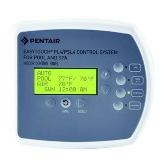
Page 29: Easytouch Pl4/Psl4 Control System Indoor Control Panel Installation
PL4/PSL4 Control System Indoor Control Panel Installation Use the following procedure to install the EasyTouch PL4/PSL4 Control System Indoor Control Panel. Read through the installation procedure before starting. The PSL4 Control System Indoor Control panel provided one touch controls for your pool, spa, lights and other functions from inside your home or a sheltered location. - Page 30 COM PORT - J20 connector: For IntelliFlo ® Pump, iS4 Spa Side Remote QuickTouch ® PL4/PSl4 Control System Indoor Control Panel and Pl4/PSL4 Control System Wireless Controller Transceiver. EasyTouch PL4/PSL4 Control System Circuit Board EASYTOUCH PL4/PSL4 Control System Installation Guide ®...
- Page 31 PL4/PSL4 Control System Indoor Control Panel To mount and connect the communication cable to the EasyTouch PL4/PSL4 Control System Indoor Control Panel: 1. Route the cable through the house wall to the location of the indoor control panel. Pull a working length of the communication cable out of the wall.
- Page 32 Front cover Screw terminal pin-outs Pin 1 GND / BLACK Pin 2 -DT / GREEN Pin 3 + DT / YELLOW Pin 4 15 V / RED EasyTouch PL4/PSL4 Control System Indoor Control Panel EASYTOUCH PL4/PSL4 Control System Installation Guide ®...
-
Page 33: Easytouch Pl4/Psl4 Control System Quicktouch Ii Wireless Controller Installation
The Transceiver is a two-way radio device with an attached antenna that communicates to and from the EasyTouch PL4/PSL4 control system via the wireless hand-held wireless control panel. Mount the Transceiver module at a convenience location (on a flat vertical surface) near the Power Center, at a minimum of 5 ft. - Page 34 9. Slide the case over the back plate. Secure the case to the back plate using the two retaining screws. 10. Proceed with “Connecting the Transceiver to the EasyTouch PL4/PSL4 Control System Power Center,” on page 27. Case...
- Page 35 PL4/PSL4 Control System Power Center WARNING Switch OFF the main system power to the EasyTouch PL4/PSL4 Control System Power Center before making any connections. 1. Unlatch the enclosure door spring latch, and open the enclosure door. 2. Remove the two retaining screws securing the high voltage cover panel, and remove it from the enclosure.
-
Page 36: Easytouch Pl4/Psl4 Control System Outdoor Control Panel Installation
SWITCH OFF THE MAIN POWER into the home at the main circuit breaker box. The EasyTouch PL4/PSL4 Control System Outdoor Control Panel installs in the top part of the Power Center enclosure. The control panel controls and distributes high voltage power to the valve actuators, control pumps, lights, and heater operations. - Page 37 Control Panel Retaining screw (fold down to (Outdoor Control Panel) access circuit board and low voltage Low voltage Raceway EasyTouch PL4/PSL4 Control System Power Center (front view) (front door and high voltage compartment panel removed) EASYTOUCH PL4/PSL4 Control System Installation ®...
-
Page 38: Easytouch Pl4/Psl4 Control System Circuit Board Connections
EasyTouch Connections The EasyTouch PL4/PSL4 Control System main circuit board is mounted in the top of the Power Center. The circuit board provides the voltage connections to the filter pump, heater, auxiliary relays, motorized valves and for temperature sensors. The COM port on the EasyTouch PL4/PSL4... -
Page 39: Easytouch Pl4/Psl4 Control System Wiring Diagram
® EasyTouch PL4/PSL4 Control System Wiring Diagram EASYTOUCH PL4/PSL4 Control System Installation ®... -
Page 40: System Start-Up
RETURN with INTAKE plugs on the EasyTouch PL4/PSL4 Control System circuit board. Testing the auxiliary relays Affix the auxiliary relay labels to the appropriate buttons on the EasyTouch PL4/PSL4 Control System control panel. If necessary, write the function on the control panel. •... -
Page 41: Solar System Installation
(such as pool fill line or jet air intake). Solar System Start-Up 1. Switch power on to the EasyTouch PL4/PSL4 Control System Power Center. 2. If pool cleaner protection has been added to the system, the pool cleaner pump motor should be activated whenever the pool cleaner timer is on. -
Page 42: Accessories
Plumbing Requirements It is important that the pool and spa plumbing system be in accordance with local codes and the Recommended Hydraulic Schematics (page 36 and 37). Before starting, please review the diagrams and the following recommended guidelines: The spa should be at or above the level of the pool. If the spa is attached to the pool, provide a dam between the two bodies of water to allow the spa to overflow into the pool. -
Page 43: Plumbing Requirements
Plumb the solar feed and return lines between the filter and the heater. Install a three-port valve at the feed line. Use a solar valve (model SOL-2T), to allow automatic draining of the panels. A solar booster pump should be used when the distance to the panels exceed 200 ft., or the panels are elevated higher than 25 ft. - Page 44 Pantone Colors: 429 Buttons 431 Background PL4/PSL4 Wireless PL4/PSL4 Wireless Controller Transceiver PL4/PSL4 Power Center Control Panel PL4/PSL4 Indoor Control Panel INTELLICHLOR PL4/PSL4 Wireless Transceiver PL4/PSL4 Power Center Control Panel Pantone Colors: 429 Buttons 431 Background Check Valve PL4/PSL4 Indoor PL4/PSL4 Wireless Control Panel Controller...
-
Page 45: Glossary
EasyTouch PL4/PSL4 Control System Systems User’s Guide (P/N 522461) High Voltage Panel/Compartment: Removable panel for the high voltage compartment of EasyTouch PL4/PSL4 Power Center. The high voltage wiring including 18 V and 24 V circuit breakers, relays and GFCI. - Page 46 EASYTOUCH PL4/PSL4 Control System Installation Guide ®...
- Page 47 NOTES EASYTOUCH PL4/PSL4 Control System Installation ®...
- Page 48 Pentair Water Pool and Spa, Inc. Those names and brands may be the trademarks or registered trademarks of those third parties.
Need help?
Do you have a question about the EASYTOUCH PL4 and is the answer not in the manual?
Questions and answers