Advertisement
- 1 IMPORTANT SAFETY INSTRUCTIONS
- 2 INTRODUCTION
- 3 PRE-INSTALLATION
- 4 INSTALLATION
- 5 PENTAIR HOME APP
- 6 WIRING DIAGRAM / REPLACEMENT PARTS
- 7 Documents / Resources
IMPORTANT SAFETY INSTRUCTIONS
 IMPORTANT NOTICE
This guide provides installation and operation instructions for this equipment. Consult Pentair with any questions regarding this equipment.
Attention Installer: This guide contains important information about the installation, operation and safe use of this product. This information should be given to the owner and/or operator of this equipment after installation or left on or near the equipment.
Attention User: This manual contains important information that will help you in operating and maintaining this product. Please retain it for future reference.
| READ AND FOLLOW ALL INSTRUCTIONS SAVE THESE INSTRUCTIONS
Carefully read and follow all safety instructions in this manual and on equipment. Keep safety labels in good condition; replace if missing or damaged. |
 This is the safety alert symbol. When you see this symbol on your system or in this manual, look for one of the following signal words and be alert to the potential for personal injury.
SERIOUS BODILY INJURY OR DEATH CAN RESULT IF THIS PRODUCT (UNIT) IS NOT INSTALLED AND USED CORRECTLY.
INSTALLERS, POOL OPERATORS AND POOL OWNERS MUST READ THESE WARNINGS AND ALL INSTRUCTIONS BEFORE USING THIS PRODUCT. This Guide provides installation and operation instructions for the product. Consult Pentair with any questions regarding this product.

This product is intended for use in swimming pool applications only.
Most states and local codes regulate the construction, installation, and operation of public pools and spas, and the construction of residential pools and spas. It is important to comply with these codes, many of which directly regulate the installation and use of this product. Consult your local building and health codes for more information.
A pool or spa pump must be installed by a qualified pool and spa service professional in accordance with the current National Electrical Code and all applicable local codes and ordinances. Improper installation may create an electrical hazard which could result in death or serious injury to pool users, installers, or others due to electrical shock, and may also cause damage to property.
Do not use this product to control an automatic pool cover. Swimmers may become entrapped underneath the cover.


RISK OF ELECTRICAL SHOCK OR ELECTROCUTION!
Always disconnect power at the circuit breaker before servicing the enclosure or equipment connected to the enclosure. Failure to do so could result in death or serious injury to service professionals, pool users or others due to electrical shock.
This product must be installed by a licensed or certified electrician or a qualified pool professional in accordance with the current National Electrical Code (NEC), NFPA 70 or the Canadian Electrical Code (CEC), CSA C22.1. All applicable local installation codes and ordinances must also be adhered to. Improper installation will create an electrical hazard which could result in death or serious injury to pool users, installers or others due to electrical shock, and may also cause damage to property.

Water temperature in excess of 100°F (37.7°C) may be hazardous to your health. Prolonged immersion in hot water may induce hyperthermia. Hyperthermia occurs when the internal temperature of the body reaches a level several degrees above normal body temperature of 98.6°F (37°C).
Effects of hyperthermia include:
- Unawareness of impending danger.
- Failure to perceive heat.
- Failure to recognize the need to leave the spa.
- Physical inability to exit the spa.
- Fetal damage in pregnant women.
- Unconsciousness resulting in danger of drowning. The use of alcohol, drugs, or medication can greatly increase the risk of fatal hyperthermia in hot tubs and spas.

HAZARDOUS PRESSURE: STAND CLEAR OF PUMP AND FILTER DURING START UP.
Circulation systems operate under high pressure. When any part of the circulating system (i.e. locking ring, pump, filter, valves, etc.) is serviced, air can enter the system and become pressurized.
Pressurized air can cause the pump housing cover, filter lid, and valves to violently separate which can result in severe personal injury or death. Filter tank lid and strainer cover must be properly secured to prevent violent separation. Stand clear of all circulation system equipment when turning on or starting up pump.
Before servicing equipment, make note of the filter pressure. Be sure that all controls are set to ensure the system cannot inadvertently start during service. Turn off all power to the pump.

Place filter manual air relief valve in the open position and stand clear of the filter until all pressure has been relieved and the pressure gauge reads 0 psi.
Before starting the system, fully open the manual air relief valve and place all system valves in the "open" position to allow water to flow freely from the tank and back to the tank. Stand clear of all equipment and start the pump.
Do not close filter manual air relief valve until all pressure has been discharged from the valve and a steady stream of water appears. Observe filter pressure gauge and be sure it is not higher than the pre-service condition.
The use of alcohol, drugs, or medication can greatly increase the risk of fatal hyperthermia in hot tubs and spas.
For units intended for use in other than singlefamily dwellings, a clearly labeled emergency switch shall be provided as part of the installation. The switch shall be readily accessible to the occupants and shall be installed at least 5 feet (1.5 m) away, adjacent to, and within sight of, the unit.


For Installation of Electrical Controls at Equipment Pad (ON/OFF Switches, Timers and Automation Load Center)
Install all electrical controls at equipment pad, such as on/off switches, timers, and control systems, etc. to allow the operation (startup, shut-down, or servicing) of any pump or filter so the user does not place any portion of his/her body over or near the pump strainer lid, filter lid or valve closures. This installation should allow the user enough space to stand clear of the filter and pump during system start-up, shut down or servicing of the system filter.
General Installation Information
|
Except for listed spa-side remote controls, install a minimum of 5 feet (1.5 m) from the inside wall of the pool and spa.
The electrical supply for this product must include a suitably rated switch or circuit breaker to open all ungrounded supply conductors to comply with the current National Electrical Code (NEC), NFPA 70 or the Canadian Electrical Code (CEC), CSA C22.1. All applicable local installation codes and ordinances must also be adhered to.
Use only copper supply conductor's rated for 60C/75C sized based on ampacity to support all loads (refer to NEC tables)
To reduce the risk of injury, do not permit children to use this product unless they are closely supervised at all times.
CUSTOMER SERVICE / TECHNICAL SUPPORT
Hours: 8:00AM to 7:30PM EST (5:00AM - 4:30PM PST)
Call: (800) 831-7133
Visit: www.pentair.com
Fax: (800) 284-4151
INTRODUCTION
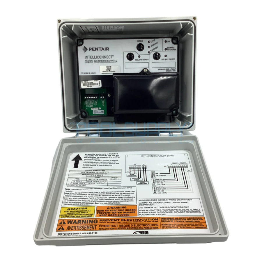
The IntelliConnect® Control and Monitoring System provides control of 120/240 VAC equipment, pumps, lighting and chlorinators. Pool and spa operations can be controlled via a mobile device with the Pentair Home app, or manually controlled from the control panel housed inside the enclosure.
Enclosure Overview
- Dimensions: 8-1/8" H x 12-1/8" W x 5-3/8" D
- Separate high voltage and low voltage wiring compartments with 1/2-inch conduit knockouts. One knockout for incoming power to power the unit and one knockout for each relay and a webbed low voltage cable snap bushing.
- Control, monitoring and scheduling via mobile device
- Two 16-Amp, 2 HP relays
- 120/240 VAC
Control Panel Overview
Buttons
MODE: Cycles through Auto, Service and Timeout modes
RELAY 1: Activates equipment wired to Relay 1. Depending on software version, when pressed, the system may enter Service Mode.
RELAY 2: Activates equipment wired to Relay 2. Depending on software version, when pressed, the system may enter Service Mode.
LEDs
AUTO: Control via mobile devices is allowed
SERVICE: Control via mobile devices is prevented
TIMEOUT: Control via mobile devices is prevented for 3 hours
LINK:
- SOLID GREEN: wireless connection established
- BLINKS GREEN: unit in access point mode or searching for a 2.4 GHz router connection
- BLINKS RED: access point mode has timed out or wireless connection can not be found
DEMAND RESPONSE: SOLID RED when a Demand Response has been activated by the electrical utility. Homeowner must contact the utility to participate.
Note: During a demand response the pump can run outside of its scheduled time. The pump could turn on, off, decrease or increase speed without warning. Always disconnect power to the pump at the circuit breaker before servicing any part of the filtration system.
RELAY 1 ON/OFF: GREEN when Relay 1 is active; RED when a fault involving Relay 1 is detected.
RELAY 2 ON/OFF: GREEN when Relay 2 is active; RED when a fault involving Relay 2 is detected.

PRE-INSTALLATION
Location and Installation Guidelines
Before installing the IntelliConnect enclosure, read the following guidelines carefully:
- Install the provided antenna onto the outer left-side of the enclosure hand tight.
Note: Older models may not include an external antenna.
- Before permanent installation, test the wireless signal strength at the desired install location (refer to Testing Wireless Signal Strength).
- 2.4 GHz bandwidth WiFi router required.
- If possible, minimize the number of obstacles that may block the wireless signal to the enclosure.
- All electrical equipment must be installed at least 5 ft. (1.5 m), [in Canada, 3 m (9.8 ft.)] from pool and/or spa, and comply with all national, state, and local codes.
- Install the enclosure at least 5 ft. (1.5 m) from the inside wall of the pool, spa and/or hot tub.
- The installation should allow the user enough space to stand clear of the filter and pump during system start-up.
| For Installation of Electrical Controls at Equipment Pad (ON/OFF Switches, Timers and Automation Load Center) Install all electrical controls at equipment pad, such as on/off switches, timers, and control systems, etc. to allow the operation (startup, shut-down, or servicing) of any pump or filter so the user does not place any portion of his/her body over or near the pump strainer lid, filter lid or valve closures. This installation should allow the user enough space to stand clear of the filter and pump during system start-up, shut down or servicing of the system filter. |
- The enclosure can be mounted outside or inside of a pool equipment shed or other structure.
- Before choosing the final location for the enclosure, consider the length of all conductors that will be connected to the enclosure. Make sure to consider cable lengths for the sensors to the enclosure location.
- Mount the enclosure on a flat vertical surface and ensure conduit knockouts are facing the ground.
Note: Failure to mount the enclosure correctly can lead to water entering the conduit knockout, causing damage to the system and creating a possible electrical shock hazard.
- Motors should be listed for pool and spa applications and have built-in thermal protection.
- Allow unobstructed access to the front of the enclosure.
- Grounding wires coming into the enclosure must be capped with appropriately sized wire nuts (not included).
Testing Wireless Signal Strength
Before permanently installing the enclosure, follow the instructions below to ensure wireless signal is strong enough at the installation site to successfully pair IntelliConnect.
- Ensure the power is turned off at the circuit breaker before wiring the IntelliConnect system.
- Unfasten the two Lid Clips on top of the enclosure and open the lid.
- Remove the retaining screw securing the high voltage wiring compartment cover and remove the high voltage cover.
- At the proposed mounting location, bring 120/240 VAC power into the high voltage wiring compartment and temporarily wire to screw terminals marked L1 and L2/N (seeFIGURE 4).
Note: Cap the ground wire to ensure electricity does not arc to a hot wire or the control board.
- Reinstall the high voltage cover over the high voltage wiring compartment and secure with the retaining screw.
- Return power to IntelliConnect at the circuit breaker.
- Follow the instructions given inPairing to a Router via Pentair Home App.
- The LINK LED will temporarily blink green when power is first returned to IntelliConnect. After a few seconds the LINK LED will be:
- BLINKING GREEN: IntelliConnect is in access point mode or is searching for a connection with the 2.4 GHz router signal.
- SOLID GREEN: Successful wireless connection between the IntelliConnect and the router has been established. Proceed to Mounting the IntelliConnect.
- BLINKING RED: Unsuccessful wireless connection to the IntelliConnect and access point mode has timed out. Power down the IntelliConnect for 10 seconds to reset access point mode and proceed to STEP 9 for recommendations on improving the signal/connection strength.
Note: Ensure the router password was entered correctly into Pentair Home before continuing to STEP 9. Entering an incorrect password will result in an unsuccessful connection.
Note: If the IntelliConnect drops a wireless connection, it may take up to 3 minutes before the LINK LED begins to blink red.
- If the wireless signal from the router is not strong enough to successfully pair with the IntelliConnect system, the signal strength may be improved by:
- Moving the router closer to IntelliConnect or to an area with fewer obstructions between them.
- Moving IntelliConnect closer to the router or to an area with fewer obstructions between them.
- Installing a wireless range extender to extend the wireless signal from the router.
INSTALLATION
Mounting the IntelliConnect
| For Installation of Electrical Controls at Equipment Pad (ON/OFF Switches, Timers and Automation Load Center) Install all electrical controls at equipment pad, such as on/ off switches, timers, and control systems, etc. to allow the operation (startup, shut-down, or servicing) of any pump or filter so the user does not place any portion of his/her body over or near the pump strainer lid, filter lid or valve closures. This installation should allow the user enough space to stand clear of the filter and pump during system start-up, shut down or servicing of the system filter. |
The enclosure must be mounted, at eye level, to a flat vertical surface, such as a wall or post.
The enclosure must be at least 5 ft. [1.5 m], (in Canada, 3 m [9.8 ft.]) from the inside wall of the pool, spa and/or hot tub.
- Position the enclosure against a vertical flat surface, ensuring it is horizontally level and square.
Note: If wall anchors are being used, place the enclosure against the mounting surface and mark the Mounting Points (FIGURE 2).

- Secure each side of the enclosure at the Mounting Points (FIGURE 2).
Connecting to Power
Some pool equipment requires connection to ground fault circuit breakers (GFCI). Check all current local and NEC (CEC) codes to determine specific requirements. For recommended field conductor gauge usage, refer to the circuit breaker label.
Wiring to Enclosure: 14 AWG minimum copper conductors for relays and other equipment sized according to the amps used.
- Open the enclosure by unfastening the two Lid Clips (FIGURE 3) at the top of the enclosure.

- Remove the Retaining Screw (FIGURE 3) securing the high voltage wiring compartment cover and remove the high voltage cover.
- Route 120/240 VAC power into the high voltage wiring compartment and wire to screw terminals marked L1 and L2/N (FIGURE 4).


 ALWAYS ensure the high voltage cover is installed and secured to the wiring compartment before powering on this equipment. Powering on this equipment while the high voltage cover is removed can lead to electrical shock. |
Powering System Relays
- Route 120/240 VAC power into the high voltage wiring compartment and wire to LINE1 and LINE2 to power Relay 1.
- Send power out from LOAD1 and LOAD2 to the equipment you wish to have on Relay 1.
- If desired, repeat steps 1 and 2 to connect equipment to Relay 2.
- After electrical connections have been completed reinstall the high voltage wiring compartment cover and secure with screw.
- Close the enclosure lid and secure it with the two Lid Clips.
Wiring Filter Pumps
IntelliConnect includes two relays, as well as terminal blocks for heater, water temperature sensor and RS-485 connections. These support manual, schedule and egg timer functions. They can be turned on and off via the Pentair Home app or by placing IntelliConnect into Service mode.
Connected equipment can NOT be controlled remotely while IntelliConnect is in Service or Timeout Mode. Remote control is only possible while in Auto Mode.
Single Speed Filter Pump
A single speed filter pump should be wired to either Relay 1 or Relay 2 (FIGURE 5). Check the electrical rating marked on the pump motor before connecting it to the system.

If a single speed filter pump is the main filtration pump it must be designated as "Single Speed Filter Pump" in the Pentair Home app.
Note: Before allowing a Salt Chlorine Generator, Heater, Booster Pump or other flow-dependent equipment to activate, the Filter Pump relay must detect at least 100 Watts on the LINE1 and LOAD1 terminals. Refer to Wiring Diagram.
IntelliFlo Variable Speed Pump
Each IntelliFlo Variable Speed Pump is shipped with a 50 ft. (15.2 m) RS-485 communication cable. This cable will be used to connect IntelliFlo to IntelliConnect's RS-485 Terminal (FIGURE 5).
Note: The IntelliFlo should have constant power supplied from a GFCI breaker.
IntelliConnect is not compatible with IntelliFlo VF (P/N 011012), IntelliFlo VS (P/N 011013) and IntelliPro VS (P/N P6E6T4H-209L) pumps.
To wire an IntelliFlo pump to IntelliConnect:
- Switch OFF power to the pump and IntelliConnect at the main circuit breaker.
- Run the RS-485 communication cable from the pump to the IntelliConnect.
- Strip the cable 3/4" (19 mm).
- Strip the GREEN and YELLOW conductors 1/2" (13 mm). Cut off and terminate unused conductors according to local and national electrical codes.
- Insert the cable conductors into the left-most Grommet Fitting (FIGURE 5) and pull the cable into the wiring compartment.
- Insert the GREEN and YELLOW conductors into the RS-485 Terminal (FIGURE 5) according to the markings on the control board and secure them in place.
Note: Multiple conductors may be inserted into a single screw terminal.
- Refer to the pump installation and user's guide for instructions on programming the pump.
SuperFlo VST or SuperMax VS External Control via RS-485 Connection
The following instructions only apply to SuperFlo VST and SuperMax VS pumps manufactured after 10/15/20. These pumps can be controlled via an RS485 signal when paired with the RS-485 Automation Wiring Kit (P/N 356324z).
Note: If the pump is manually stopped using the START/STOP button, the pump will not run until the START/STOP button is pressed. If the Start/Stop LED is illuminated, the pump is active and can be controlled externally.
If the designation "SuperFlo VST" or "SuperMax VS" does not display when adding the pump to the Pentair Home app, the pump should be designated as "Pentair VS (RS485)".
To wire a SuperFlo VST or SuperMax VS pump to IntelliConnect, follow the wiring instructions in the IntelliFlo Variable Speed Pump section.
Note: Only the GREEN and YELLOW conductors will be used when wiring the pump for external control via RS-485.
Note: When correctly connected to IntelliConnect the pump screen with alternate "Auto" and "1".
To allow a SuperFlo VST or SuperMax VS pump to be controlled via IntelliConnect:
- At the pump, press the START/STOP button to stop the pump.
- Ensure the pump address is set to "1" on the pump controller.
- Ensure IntelliConnect is operating with the latest firmware version.
- Press the "1" button and ensure the Speed LED is blinking.
- Set pump speed to 0.
- Press the "1" button twice and ensure the Duration LED is blinking.
- Set the program duration to 24 hours.
- Press the START/STOP button to restart the pump.
Wiring Flow-Dependent Equipment
Equipment wired to Relay 1 or Relay 2 (FIGURE 6), and designated as either "Other (Flow Dependent)" or "Booster Pump" in the Pentair Home app, will not energize until the filter pump has run for 2 minutes and allowed the system time to prime.

Note: A relay designated as "Other (Flow Dependent)" will not activate during Freeze Protection.
If a single speed pump is the filter pump, that relay must be designated as "Single Speed Filter Pump" in the Pentair Home app to be recognized as such.
If an IntelliFlo pump connected via RS-485 is the filter pump, IntelliConnect will recognize it as such, unless there is a separate relay designated as "Single Speed Filter Pump" in the Pentair Home app.
Booster Pump
A booster pump should be wired to one of the two Relay terminals (FIGURE 6). Check the electrical rating marked on the pump motor before connecting it to the system.
In the Pentair Home app, the booster pump should be designated as "Booster Pump". If freeze protection is activated, this relay will activate.
Wiring a Salt Chlorine Generator (SCG)
When a salt chlorine generator is connected to IntelliConnect, a single speed pump designated as "Single Speed Filter Pump" or IntelliFlo pump MUST be connected.
A salt chlorine generator should be wired to one side of the RS-485 Terminal (FIGURE 6) according to the markings on the control board.
When an IntelliChlor or iChlor SCG is wired to IntelliConnect via an RS-485 cable, a power connection to the load side of the pump relay is not required. Digital commands sent from the IntelliConnect to the SCG will not allow chlorine production when there is low/no power to the single speed pump relay or when the IntelliFlo is not running.
Only wire the RS-485 cable's YELLOW and GREEN conductors to the RS-485 Terminal. Cut off and terminate unused conductors according to local and national electrical codes.
To adjust chlorine output while in Service mode: Place the IntelliConnect into Service mode, wait for three minutes, then adjust the output at the salt cell. The chlorine generator will operate at the new output once it is placed into Auto mode.Wiring a Heater or Heat Pump
Water Temperature Sensor
When connecting a heater to IntelliConnect, a water temperature sensor (sold separately) must be installed between the filter pump and filter. Refer to the sensor manual for specific sensor installation instructions.
To wire a water temperature sensor to IntelliConnect:
- Switch OFF power to IntelliConnect at the main circuit breakers.
- Run the 22 AWG, two-conductor cable from the sensor to the IntelliConnect.
- Insert the cable into the left-most Grommet Fitting (FIGURE 7) and pull the cable into the wiring compartment.

- Strip the outer sheath of the cable 1" (25 mm), exposing the two conductors. Strip back each conductor 1/2" (13 mm).
- Insert the conductors into the Temperature Sensor terminal ("A" in FIGURE 7) and secure the individual wires in their corresponding slots.

Heater or Heat Pump
IntelliConnect contains low-voltage dry contacts that can be connected to most gas heaters or heat pumps with 24 VAC control circuits.
When a heater or heat pump is connected to IntelliConnect, a single speed pump designated as "Single Speed Filter Pump" or an IntelliFlo pump, MUST also be connected.
While IntelliConnect is in Service Mode, simultaneously pressing and holding the Relay 1 and Relay 2 buttons for 3 seconds will activate the heater. The Demand Response LED will illuminate amber.
To wire a gas heater or heat pump to IntelliConnect:
- Switch OFF power to the heater and IntelliConnect at the main circuit breakers.
- Remove the factory installed jumper from the heater "Ext Switch" or fireman's switch.
| DO NOT disconnect or remove the jumper on the thermostat, pressure switch, high limit switch or other safety devices. Disconnecting these jumpers will cause improper heater operation and could lead to personal injury or damage to the equipment. |
- At the heater, wire a two-conductor cable to the heater's Ext Switch connection. Ensure the cable meets the minimum temperature and gauge ratings given in the heater manual or installation instructions.
Note: Use caution when wiring to the Ext Switch connection. Internal heater components may be hot.
Note: Ensure this cable is not near or touching any line voltage conductors inside the heater. This could cause the heater to malfunction.
- Run the cable from the heater to the IntelliConnect.
- Insert the cable into the left-most Grommet Fitting (FIGURE 7) and pull the cable into the wiring compartment.
- Strip the outer sheath of the cable by 1" (25 mm), exposing two conductors. Strip each conductor 1/4" (6 mm).
- Insert the conductors into the Heater Terminal ("B" in FIGURE 7) and secure the individual conductors.
- At the heater control panel, set both the Pool and Spa thermostats to maximum desired temperatures and select either Pool or Spa run mode.
Note: If temperatures set at the heater control panel are lower than those set in the Pentair Home app, the heater will not heat above the heater control panel settings.
Wiring Pool Lights
A pool light should be wired to Relay 1 or Relay 2 (FIGURE 7). Check the electrical rating marked on the light housing before connecting it to the system.
PENTAIR HOME APP
Creating a Pentair Home Account
- From your chosen smart device, download Pentair Home from the Google Play® store (Android® devices) or Apple® App Store® (iOS® devices).
Note: Apple operating systems must be iOS 11 or later. Android operating systems must be version 6.0 or later.
- Open the Pentair Home app (
![]() ) from your smart device.
) from your smart device. - At the Login screen, press SIGN UP at the bottom of the screen.
- Continue to follow the in-app instructions.


Pairing to a Router via Pentair Home App
IntelliConnect must be paired to your home WiFi router before it can be added to your Pentair Home account.
The WiFi router must be within range of the IntelliConnect during the pairing process.
TO PAIR INTELLICONNECT TO A WIFI ROUTER:
- Follow the in-app pairing instructions.
- The Connection Status screen will display. This screen will indicate:
- WIFI CONNECTED: The correct password has been entered and IntelliConnect is trying to receive information through the WiFi connection.
- SERVER CONNECTED: IntelliConnect has received information from the server.
If SERVER CONNECTING continues to display, this could indicate an issue with the router, WiFi extender or internet service provider.
If IntelliConnect is connected to a WiFi extender, verify the extender is connected to the internet by pairing your smart device to the extender and opening a WiFi dependent app.
- Once the IntelliConnect has successfully paired to the WiFi router and sent information out to the internet the IntelliConnect's LINK LED will illuminate solid green.
- Continue to Adding IntelliConnect to a Pentair Home Account.
Pairing to a Router without Pentair Home
IntelliConnect must be paired to your WiFi network before IntelliConnect can be accessed from the Pentair Home app.
Pentair recommends pairing IntelliConnect via the Pentair Home app (refer to Pairing to a Router via Pentair Home App, for instructions). The following instructions cover an alternative way to pair IntelliConnect to your WiFi router. The router must be within range of the IntelliConnect during the pairing process.
TO PAIR INTELLICONNECT TO A WIFI ROUTER:
- Disconnect power to the IntelliConnect for 10 seconds, and then return power to the unit to activate an access point for 10 minutes. The LINK LED will be blinking green.
- Open your computer, smartphone or tablet's wireless settings.
- To open Wireless Settings on smart phones or tablets: Go to Settings > WiFi or Settings > Connections > WiFi.
- To open Wireless Settings on computers: Click on the wireless icon [
![]() or
or ![]() ] in the desktop system tray.
] in the desktop system tray.
- You should see an available access point titled "PNRA1PIFXXXXXXXX". Select this access point.
- Open your web browser and enter 192.168.123.1 into the address bar. Press enter.
- The pairing page will display. Select your WiFi router from the drop down SSID list and enter your router password into the security key field. See FIGURE 8.
![]()
 or
or  ] in the desktop system tray.
Note: Passwords are case sensitive.
Note: If your WiFi router does not display in the SSID drop down list and the LINK LED is still flashing green:
- The router list may need to be refreshed. Close the drop down menu and reopen. Repeat this until your router appears.
- If the router does not appear after several refreshes, the router may be too far from the IntelliConnect to receive a strong enough signal. Refer toTesting Wireless Signal Strength, for steps to correct this issue.
- Press CONNECT. See FIGURE 8.
- The Connection Status screen will display. This screen will indicate:
- WIFI CONNECTED: The correct password has been entered and IntelliConnect is trying to receive information through the WiFi connection.
- SERVER CONNECTED: IntelliConnect has received information from the server.
If SERVER CONNECTING continues to display, this could indicate an issue with the router, WiFi extender or internet service provider.
If IntelliConnect is connected to a WiFi extender, verify it is connected to the internet by pairing your smart device.
- Once the IntelliConnect has successfully paired to the WiFi router and sent information out to the internet the IntelliConnect's LINK LED will illuminate solid green.
Adding IntelliConnect to a Pentair Home Account
- At the Account Dashboard, press the Devices tab (1).
- The My Devices screen will display (FIGURE 9). Press the "+" symbol (2).
![]()
- The Add a Device screen will display (FIGURE 10). Press INTELLICONNECT.
![]()
- The Check Your IntelliConnect screen will display. Select whether your IntelliConnect has a PIF or PNR label.
- The Enter the PIF/PNR screen will display (FIGURE 11). Enter the number twice. A green check mark will display if entered correctly.
![]()
- Press NEXT (3) in the top-right corner of the screen.
- The Device Address screen will display. Enter and SAVE the correct address.
- The Device Nickname screen will display. Enter the name you wish your IntelliConnect to display on the Home Dashboard and press SAVE.


Note: Special characters are NOT allowed in your IntelliConnect nickname
- At the Getting Started with IntelliConnect screen (FIGURE 12):
![]()

- If IntelliConnect has not been paired to a WiFi network, complete the on-screen instructions then press CONNECT (4).
- If IntelliConnect has already been paired to a WiFi network, press SKIP (5).
- If there is a successful connection, "Installation Completed" will appear. Press CONTINUE.
Note: If "Installation Completed" does not display, repeat the steps above.
Freeze Protection Mode
In areas that experience a short period of freezing temperatures, Freeze Protection Mode should be activated by sliding the Freeze Protection Mode toggle to the ON position. However, freeze protection will not guarantee protection from damage to pool, equipment or property during extended periods of cold.
A strong and stable wireless connection is required for properly syncing freeze protection, as IntelliConnect uses data from an internet based weather service and updates hourly.
| If your wireless connection, internet or the weather service website is not working the IntelliConnect freeze protection feature will not function. Additional steps will be required to avoid property damage from freezing temperatures. Follow the instructions given in the pump and other equipment manuals to prevent freeze damage. |
Freeze protection is designed to run the filter pump when air temperatures drop below the freeze protection set point for a short period of time. IntelliConnect must be operating in Auto mode to allow the freeze protection feature to activate the filter pump.
Note: Freeze Protection Mode allows IntelliConnect to enable a disabled variable speed pump. If winterizing the pool filtration system, ensure power to the pump is disconnected at the circuit breaker.
Contact your local pool professional for additional information on pool winterization.
WIRING DIAGRAM / REPLACEMENT PARTS
Wiring Diagram
Both sides of the electrical connection must be run through a relay for the connected equipment to operate properly. If one side of the connection is broken, the circuitry will not be able to accurately detect circuit amperage.
Amperage detection allows IntelliConnect to safely activate a heater or salt chlorine generator. It also detects whether relay equipment is on or not.
IntelliChlor/iChlor salt chlorine generators, IntelliFlo pumps and heaters should receive power directly from the breaker (to receive constant power) and should not be wired through Relay 1 or Relay 2.

| CONTROL BOARD RATINGS | ||
| Input: 100-240 V, 100 mA, 50/60 Hz | ||
| RELAY CONTACT RATINGS (60 Hz) | ||
| General: 16 A, 277 V | ||
| PUMP | LIGHT | HEATER |
| 1 HP, 120 V | 1 kW, 120 V TUNGSTEN | 0.5 A, 24 V |
| 2 HP, 240 V | 1.3 kW, 240 V TUNGSTEN | |
| 16 FLA/96 LRA, 120 V | 10 A, 240 V BALLAST | |
| 15 FLA/90 LRA, 240 V | ||
Replacement Parts
| P/N | Description |
| 523327 | Control Board Kit |
1620 HAWKINS AVE., SANFORD, NC 27330 • (919) 566-8000 10951 WEST LOS ANGELES AVE., MOORPARK, CA 93021 • (805) 553-5000
WWW.PENTAIR.COM
Documents / Resources
References
Download manual
Here you can download full pdf version of manual, it may contain additional safety instructions, warranty information, FCC rules, etc.
Advertisement


Need help?
Do you have a question about the INTELLICONNECT and is the answer not in the manual?
Questions and answers