Table of Contents
Advertisement
Quick Links
Advertisement
Table of Contents

Related Manuals for Moxa Technologies ioMirror E3210


Summary of Contents for Moxa Technologies ioMirror E3210
- Page 1 E3210 User’s Manual www.moxa.com/product First Edition, May 2007 Moxa Technologies Co., Ltd. Tel: +886-2-8910-1230 Fax: +886-2-8910-1231 Web: www.moxa.com Moxa Technical Support Worldwide: support@moxa.com The Americas: support@usa.moxa.com...
-
Page 2: Copyright Notice
The software described in this manual is furnished under a license agreement and may be used only in accordance with the terms of that agreement. Copyright Notice Copyright © 2007 Moxa Technologies Co., Ltd. All rights reserved. Reproduction without permission is prohibited. -
Page 3: Table Of Contents
Table of Contents Chapter 1 Introduction ....................1-1 Welcome..........................1-2 Features ..........................1-3 Infrastructure Examples......................1-4 Ethernet Network ....................1-4 Fiber Optic Network ....................1-4 Wireless LAN ......................1-4 Package Checklist......................... 1-4 Specifications ........................1-5 LAN ........................1-5 Digital Input......................1-5 Digital Output ...................... - Page 4 3xxxx Read Only Registers (Function 4)..............B-1 4xxxx Read/Write Registers (Functions 3, 6, 16) ...........B-2 Function 8 .......................B-2 Appendix C Used Network Port Numbers............... 3 ioMirror E3210 Network Port Usage ..................3 Appendix D Factory Default Settings ................D-1 Appendix E Pinouts and Cable Wiring................ E-1 Port Pinout Diagrams ......................
-
Page 5: Chapter 1 Introduction
Introduction Chapter 1 The ioMirror E3210 is a peer-to-peer Ethernet I/O server that acts as a cable replacement solution for connecting digital input sensors to PLC controller or DCS systems. Typical applications involve using a pair of ioMirror servers, one on each end of the connection. -
Page 6: Welcome
Introduction Welcome The ioMirror E3210 is a cable-replacement solution that connects digital input signals to digital outputs over an IP network. It is equipped with 8 digital inputs, 8 digital outputs, and a 10/100Mbps Ethernet interface. A pair of ioMirror servers can connect remote sensor signals to a PLC controller, DCS systems, or a display device over Ethernet, eliminating the need to install additional signal wires. -
Page 7: Features
Features High speed mirroring of digital I/O signals over Ethernet The ioMirror E3210 transmits digital I/O signals over Ethernet at very high speeds, with less than 20 ms latency in a local area 100Mbps network. The extremely low latency makes ioMirror E3210 an excellent choice for transmitting low and middle-speed signals, such as liquid level or optical sensor input. -
Page 8: Infrastructure Examples
Fiber Optic Network Wireless LAN Package Checklist Standard Accessories ioMirror E3210 peer-to-peer Ethernet I/O server Document and Software CD Optional Accessories LDP1602 ioMirror LCD display kit NOTE: Notify your sales representative if any of the above items are missing, or damaged. -
Page 9: Specifications
E3210 User’s Manual Introduction Specifications 10/100BaseTx with MDI/MDIX, RJ45 Interface DHCP, BootP, TCP, UDP, IP, ICMP, ARP, HTTP, SNTP, ioMirror Protocols Modbus/TCP up to 3 sockets 1.5 KV magnetic isolation Protection Fixed, dynamic (DHCP) IP Address Default 192.168.127.254 Digital Input... -
Page 10: Power
E3210 User’s Manual Introduction Power 24 VDC nominal, 12 (min) to 48 VDC (max) Power Input 3.26 W @ 24 VDC (typical) Power Consumption 24 VDC nominal, up to 48 VDC DO Power I/O cable max 14 AWG Wiring Environmental -10 to 60°C... -
Page 11: Physical Dimensions
E3210 User’s Manual Introduction Physical Dimensions Units = mm 5.95 12.22 40.39 10.7 46.51 10.98 93.02 121.8... -
Page 12: Hardware Overview
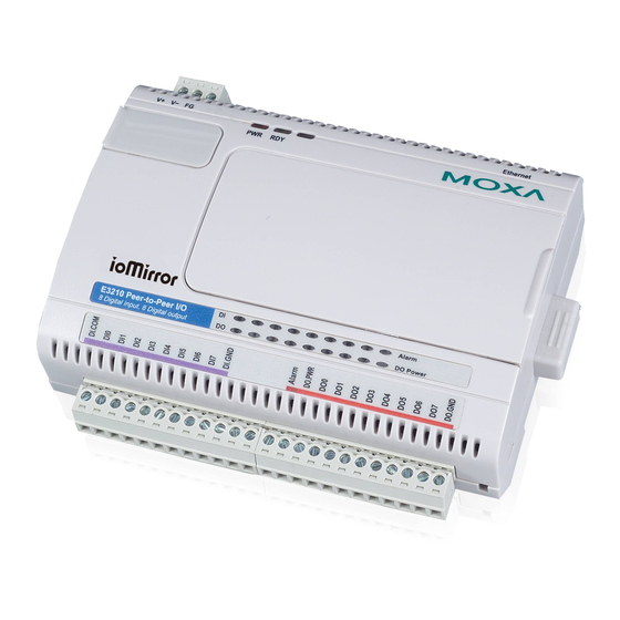
E3210 User’s Manual Introduction 44.5 35.1 57.5 Hardware Overview Please note that the LCD display module is an optional accessory. Reset Button – The reset button is used to load factory defaults. Use a pointed object, such as a straightened paper clip or toothpick, to hold the reset button down for 5 seconds. -
Page 13: Led Indicators
E3210 User’s Manual Introduction Power (TB1) I/O (TB2) (Left to right) DI COMM DI GND Signal Alarm DO PWR DO GND Signal LED Indicators Ethernet LEDs Orange Live 10Mbps Ethernet connection Ethernet Green Live 100Mbps Ethernet connection Flashing Transmitting or receiving data... -
Page 14: Chapter 2 Hardware Installation
Hardware Installation Chapter 2 This chapter explains how to install the ioMirror E3210 peer-to-peer Ethernet I/O server. The following topics are covered in this chapter: Connecting the Hardware Connecting the Power Grounding the Unit Connecting to the Network Connecting the I/O Device... -
Page 15: Connecting The Hardware
E3210 User’s Manual Hardware Installation Connecting the Hardware Connecting the Power Connect your 12 to 30 VDC power supply to the ioMirror’s terminal block. If power is properly supplied, the “Power” LED will light up red until the system is ready. -
Page 16: Setting The Ip Address
Alarm Output Setting the IP Address Static or Dynamic IP The ioMirror E3210 supports both static and dynamic IP addresses. You may need to consult with your network administrator to determine how IP addresses are assigned in your network environment: For a static IP environment, you can enter a specific IP address using ioMirrorAdmin or the web console. -
Page 17: Modifying Ip Address
E3210 User’s Manual Hardware Installation Modifying IP Address There are several ways to modify the ioMirror’s IP address. ioMirrorAdmin is a Windows utility that can be used locally or on the network to configure the unit and upgrade the firmware. Please refer to Chapter 4 for instructions on using ioMirrorAdmin. -
Page 18: Using The Web Console
Using the Web Console Chapter 3 The ioMirror can be configured using a standard web browser over a direct or network connection. This chapter explains how to open and use the web console. The following topics are covered in this chapter: Overview Opening the Web Console Navigation... -
Page 19: Overview
E3210 User’s Manual Using the Web Console Overview Opening the Web Console Use a standard web browser, such as Microsoft Internet Explorer, to open the web console. Simply point the browser to your ioMirror’s IP address. For initial configuration, use the ioMirror default IP address of 192.168.127.254. -
Page 20: Quick Reference
E3210 User’s Manual Using the Web Console Quick Reference The following is a quick reference guide to the pages in the ioMirror’s web console. Details for each page are presented later in this chapter. → Show model name, serial number, etc. -
Page 21: Ethernet Configurations
E3210 User’s Manual Using the Web Console Ethernet Configurations On the Ethernet Configurations page, you may assign the IP address, subnet mask, and gateway for your ioMirror server. You may also configure the IP address to be dynamically assigned by DHCP, DHCP/BOOTP, or BOOTP. -
Page 22: Iomirror Settings
E3210 User’s Manual Using the Web Console The Current Setting sets the channel’s current output status in order to test the DO connection. The Power On Setting sets the channel’s output status when the I/O server is first powered. The Alarm Status Setting sets the channel’s output status when the I/O server is in an alarm state. -
Page 23: System Management
E3210 User’s Manual Using the Web Console Module-to-Module and Channel-to-Channel modes Module-to-Module mode is used if you wish for all DI channels to be mapped to another ioMirror’s DO channels. Simply enter the destination IP address. Channel-to-Channel mode is used if you wish to individually map DI channels to separate or multiple ioMirror servers. -
Page 24: Network Connection
E3210 User’s Manual Using the Web Console Desired Hosts IP Address Netmask 192.168.0.1 to 192.168.0.0 255.255.0.0 192.168.1.1 to 192.168.1.126 192.168.1.0 255.255.255.128 192.168.1.129 to 192.168.1.1 255.255.255.128 Network Connection On the Network Connection page, you may view each TCP connection, which can make it easier to manage devices and mappings. -
Page 25: Load Factory Default
E3210 User’s Manual Using the Web Console Load Factory Default On the Load Factory Default page, you may reset the ioMirror back to its factory default settings. Save/Restart On the Save/Restart page, you may save all configuration changes and reboot the I/O server with... -
Page 26: Iomirroradmin And Ioeventlog
ioMirrorAdmin and ioEventLog Chapter 4 Two Windows utilities, ioMirrorAdmin and ioEventLog, are included to help you manage your ioMirror server over the network. The following topics are covered in this chapter: Overview Installation ioMirrorAdmin Searching for ioMirror Servers Wiring Guide ioMirror Configuration Firmware Update Restart System... -
Page 27: Overview
E3210 User’s Manual ioMirrorAdmin and ioEventLog Overview Two Windows utilities are provided with the ioMirror E3210. ioMirrorAdmin allows you to manage your unit over the network. You can configure the unit, upgrade the firmware, or refer to the unit’s wiring guide. -
Page 28: Iomirroradmin
E3210 User’s Manual ioMirrorAdmin and ioEventLog ioMirrorAdmin Searching for ioMirror Servers ioMirrorAdmin is designed for network operation. You will need to find your ioMirror unit on the network to use any of ioMirrorAdmin’s functions. In the System menu, select Auto Scan Remote I/O Server. -
Page 29: Wiring Guide
E3210 User’s Manual ioMirrorAdmin and ioEventLog Wiring Guide To view the ioMirror wiring guide, select Wiring Guide from the Help menu. ioMirror Configuration The ioMirror’s web console can be opened within ioMirrorAdmin. Select the desired unit in the left panel. -
Page 30: Firmware Update
E3210 User’s Manual ioMirrorAdmin and ioEventLog Firmware Update The ioMirror firmware can be updated through ioMirrorAdmin. Select the desired unit in the left panel. In the right panel, select the Firmware Update tab. You may obtain the latest firmware by visiting the MOXA website. -
Page 31: Configuration
E3210 User’s Manual ioMirrorAdmin and ioEventLog Configuration In the System menu, select Settings to configure ioEventLog. The Alarm Listen Port is the TCP port number that will be monitored for status events. You can modify this setting as necessary to receive signals through a firewall. It will need to match the settings for the ioMirror server that is being monitored. -
Page 32: Opening Log Files
E3210 User’s Manual ioMirrorAdmin and ioEventLog Opening Log Files You can view previously saved logs by selecting Open from the Log menu. You will be prompted for the date that you wish to view. The logs for the day that you select will be displayed in the Alarm Log Viewer window. -
Page 33: Controls
Menu Options Display Explanation / Actions This is the default screen. Enter this submenu to display information about the specific server you are viewing:: serial number name <ioMirror E3210> server location e3210 f/w ver lcm f/w ver ... - Page 34 E3210 User’s Manual LCD Display Kit Display Explanation / Actions Enter this submenu to view I/O channel status. Here are examples of settings that you might see: <ioMirror E3210> -00 = on i/o setting -07 = 0 Press up or down to navigate through the different I/O channels without having to go back to the previous menu.
-
Page 35: Appendix B Modbus/Tcp Address Mappings
Modbus/TCP Address Mappings Appendix B ioMirror E3210 Modbus Mapping 0xxxx Read/Write Coils (Functions 1, 5, 15) Reference Address Data Type Description 00001 0x0000 1 bit CH0 DO Value 0: Off 1: On 00002 0x0001 1 bit CH1 DO Value 0: Off 1: On... -
Page 36: 4Xxxx Read/Write Registers (Functions 3, 6, 16
E3210 User’s Manual Modbus/TCP Address Mappings Reference Address Data Type Description 34098 0x1001 1 word Unit ID (Ethernet=1) (4097) 34099 0x1002 1 word Product Code=0x2210 (4098) 38193 to 0x2000 72 word Get all DI channels CURRENT status 38264 (8192 to... -
Page 37: Appendix C Used Network Port Numbers
Used Network Port Numbers Appendix C ioMirror E3210 Network Port Usage Port Type Usage Web Server Modbus Communication BOOTPC DHCP 4045 ioMirror 4040 ioEventLog 4800 Auto search... -
Page 38: Appendix D Factory Default Settings
Factory Default Settings Appendix D The factory default configuration for the ioMirror E3210 is as follows: 192.168.127.254 IP address 255.255.255.0 Netmask 0.0.0.0 Gateway Disable Alarm system 5 sec Time out DI mode 0.5 ms Filter time DO mode DO alarm status... -
Page 39: Appendix E Pinouts And Cable Wiring
Pinouts and Cable Wiring Appendix E The following topics are covered in this appendix: Port Pinout Diagrams Ethernet Port Pinouts Digital I/O Structure Digital Input Structure Digital Output Structure Alarm Output Structure... -
Page 40: Port Pinout Diagrams
E3210 User’s Manual Pinouts and Cable Wiring Port Pinout Diagrams Ethernet Port Pinouts Signal Digital I/O Structure Digital Input Structure Digital Output Structure... -
Page 41: Alarm Output Structure
E3210 User’s Manual Pinouts and Cable Wiring Alarm Output Structure...
Need help?
Do you have a question about the ioMirror E3210 and is the answer not in the manual?
Questions and answers