Moxa Technologies NPort IA 5250 series User Manual
Industrial serial device servers
Hide thumbs
Also See for NPort IA 5250 series:
- User manual (194 pages) ,
- Quick installation manual (9 pages) ,
- Tech note (5 pages)
Table of Contents
Advertisement
Quick Links
Advertisement
Table of Contents

Related Manuals for Moxa Technologies NPort IA 5250 series


Summary of Contents for Moxa Technologies NPort IA 5250 series
- Page 1 NPort IA5150/5250 Series User’s Manual Second Edition, May 2006 www.moxa.com/product Moxa Technologies Co., Ltd. Tel: +886-2-8919-1230 Fax: +886-2-8919-1231 Web: www.moxa.com MOXA Technical Support Worldwide: support@moxa.com.tw The Americas support@moxa.com...
-
Page 2: Copyright Notice
Information provided in this manual is intended to be accurate and reliable. However, Moxa Technologies assumes no responsibility for its use, or for any infringements on the rights of third parties that may result from its use. -
Page 3: Table Of Contents
Table of Contents Chapter 1 Introduction ....................1-1 Overview ..........................1-2 Package Checklist......................... 1-2 Product Features ........................1-2 Product Specifications ......................1-3 Chapter 2 Getting Started ..................2-1 Panel Layout......................... 2-2 Connecting the Hardware ..................... 2-2 Wiring Requirements....................2-3 Connecting the Power....................2-3 Grounding NPort IA5150/5250 Series ................. - Page 4 Accessible IP Settings......................5-31 Auto Warning Settings......................5-32 Auto warning: E-mail and SNMP trap ............... 5-32 Event Type........................5-33 Monitor..........................5-36 Monitor Line....................... 5-36 Monitor Async......................5-36 Monitor Async-Settings....................5-36 Monitor Relay Output....................5-36 Change Password........................ 5-37 Load Factory Default......................5-37 Chapter 6 Configuring NPort Administrator.............6-1 Overview ..........................
-
Page 5: Chapter 1 Introduction
Introduction Chapter 1 Welcome to the NPort IA Series of industrial serial device servers. In this manual, we refer to the seven products in the series collectively as “NPort IA5150/5250 Series.” The seven models in the NPort IA5150/5250 Series are: 1. -
Page 6: Overview
NPort IA5150/5250 Series User’s Manual Introduction Overview The NPort IA5150/5250 series of device servers deliver easy and reliable serial-to-Ethernet connectivity for the industrial automation market. The NPort IA5150/5250 series is designed to allow any serial device to connect to an Ethernet network. The compact size of NPort IA device servers makes them an ideal choice for connecting RS-232/422/485 serial devices, such as PLCs, sensors, meters, motors, drives, barcode readers, and operator displays. -
Page 7: Product Specifications
NPort IA5150/5250 Series User’s Manual Introduction Product Specifications NPort IA5150-M-SC/5150I-M-SC/5150-S-SC/5150I-S-SC LAN Fiber Port 1 100BaseFX port (SC connector) NPort IA5150/5150I/5250 LAN Ethernet Switch Ports 2 10/100BaseT(X) ports (RJ45 connector) Protection Built-in 1.5 KV magnetic isolation Optical Fiber Distance Multi mode: 0 to 2 km, 1310 nm (62.5/125 µm, 500 MHz*km) Single mode: 0 to 40 km, 1310 nm (9/125 µm, 3.5 PS/(nm*km) Min. - Page 8 NPort IA5150/5250 Series User’s Manual Introduction Serial Communication Parameters Parity None, Even, Odd, Space, Mark Data Bits 5, 6, 7, 8 Stop Bit 1, 1.5, 2 Flow Control RTS/CTS (for RS-232 port only), XON/XOFF Transmission Speed 110 bps to 230.4 Kbps Software Features Protocols ICMP, IP, TCP, UDP, DHCP, BOOTP, Telnet, Rtelnet, DNS,...
-
Page 9: Chapter 2 Getting Started
Getting Started Chapter 2 In this chapter, we give instructions on installing NPort IA5150/5250 device servers. Software installation is covered in subsequent chapters. The following topics are covered in this chapter: Panel Layout Connecting the Hardware Wiring Requirements Connecting the Power Grounding NPort IA5150/5250 Series Connecting to the Network Connecting to a Serial Device... -
Page 10: Panel Layout
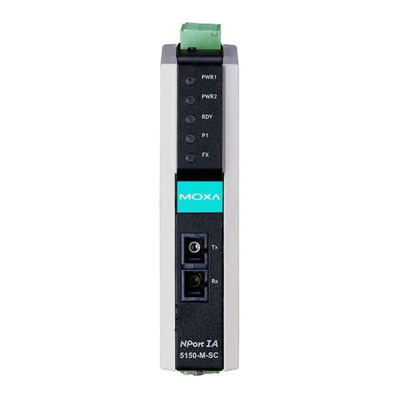
NPort IA5150/5250 Series User’s Manual Getting Started Panel Layout NPort IA5150 Series Top View Front View Bottom View PWR1 PWR2 Indicators Reset Reset Fiber optic RS-422/485 Ethernet RS-232 Dual power input 5150-M-SC and relay output NPort IA 5250 Top View Front View Bottom View PWR1... -
Page 11: Wiring Requirements
NPort IA5150/5250 Series User’s Manual Getting Started Wiring Requirements ATTENTION Safety First! Be sure to disconnect the power cord before installing and/or wiring your NPort IA5150/5250 Series. Wiring Caution! Calculate the maximum possible current in each power wire and common wire. Observe all electrical codes dictating the maximum current allowable for each wire size. -
Page 12: Connecting To The Network
NPort IA5150/5250 Series User’s Manual Getting Started SG: The Shielded Ground (sometimes called Protected Ground) contact is the left most contact of the 7-pin power terminal block connector when viewed from the angle shown here. Connect the SG wire to an appropriate grounded metal surface. -
Page 13: Led Indicators
NPort IA5150/5250 Series User’s Manual Getting Started LED Indicators The top panels of all NPort IA5150/5250 device servers have four LED indicators, as described in the following table. LED Name LED Color LED Function PWR1, Power is being supplied to power input PWR1, PWR2. PWR2 Steady on: Power is on and NPort IA is booting up. -
Page 14: Chapter 3 Initial Ip Address Configuration
Initial IP Address Configuration Chapter 3 When setting up your NPort IA5150/5250 for the first time, the first thing you should do is configure the IP address. This chapter introduces the methods that can be used to configure the device server’s IP address. Select one of the initial IP Address configuration methods to configure NPort IA5150/5250’s IP Address. -
Page 15: Initializing Nport Ia5150/5250'S Ip Address
NPort IA5150/5250 Series User’s Manual Initial IP Address Configuration Initializing NPort IA5150/5250’s IP Address 1. Determine whether your NPort IA5150/5250 needs to use a Static IP or Dynamic IP (either DHCP or BOOTP application). 2. If NPort IA5150/5250 is used in a Static IP environment, you can use NPort IA5150/5250 Administration Suite, ARP, Web Console, Telnet Console, or Serial Console to configure the new IP address. -
Page 16: Telnet Console
NPort IA5150/5250 Series User’s Manual Initial IP Address Configuration Take the following steps to use ARP to configure the IP address: 1. Obtain a valid IP address for your NPort IA5150/5250 from your network administrator. 2. Obtain NPort IA5150/5250’s MAC address from the label on its bottom panel. 3. - Page 17 NPort IA5150/5250 Series User’s Manual Initial IP Address Configuration 4. Type 2 to select Network settings, and then press Enter. 5. Type 1 to select IP address and then press Enter. 6. Use the Backspace key to erase the current IP address, type in the new IP address, and then press Enter.
- Page 18 NPort IA5150/5250 Series User’s Manual Initial IP Address Configuration 7. Press any key to continue. 8. Type m and then press Enter to return to the main menu. 9. Type s and then press Enter to Save/Restart the system. 10. Type y and then press Enter to save the new IP address and restart NPort IA5150/5250.
-
Page 19: Serial Console (19200, N, 8, 1)
NPort IA5150/5250 Series User’s Manual Initial IP Address Configuration Serial Console (19200, n, 8, 1) You may use the RS-232 console port to set up the IP address for NPort IA5150/5250. We suggest using PComm Terminal Emulator, which is available free of charge as part of the PComm Lite program suite, to carry out the installation procedure, although other similar utilities may also be used. - Page 20 NPort IA5150/5250 Series User’s Manual Initial IP Address Configuration 6. Press the “ ` ” key continuously and then power on the NPort IA5150/5250. 7. NPort IA5150/5250 will automatically switch from data mode to console mode as it receives a continuous string of “...
-
Page 21: Choosing The Proper Operation Mode
Choosing the Proper Operation Mode Chapter 4 In this chapter, we describe the various NPort IA5150/5250 operation modes. The options include an operation mode that uses a driver installed on the host computer, and operation modes that rely on TCP/IP socket programming concepts. After choosing the proper operation mode in this chapter, refer to Chapter 5 for detailed configuration parameter definitions. -
Page 22: Overview
NPort IA5150/5250 Series User’s Manual Choosing the Proper Operation Mode Overview NPort IA5150/5250 Serial Device Servers network-enable traditional RS-232/422/485 devices, in which a Serial Device Server is a tiny computer equipped with a CPU, real-time OS, and TCP/IP protocols that can bi-directionally translate data between the serial and Ethernet formats. Your computer can access, manage, and configure remote facilities and equipment over the Internet from anywhere in the world. -
Page 23: Tcp Server Mode
NPort IA5150/5250 Series User’s Manual Choosing the Proper Operation Mode ATTENTION The driver used for Real COM Mode comes with the NPort IA5150/5250 NPort Administrator. The driver is installed automatically on your computer when you install NPort IA5150/5250 Administration Suite. One of the major conveniences of using Real COM Mode is that Real COM Mode allows users to continue using RS-232/422/485 serial communications software that was written for pure serial communications applications. -
Page 24: Tcp Client Mode
NPort IA5150/5250 Series User’s Manual Choosing the Proper Operation Mode TCP Client Mode In TCP Client mode, NPort IA5150/5250 can TCP Client Mode actively establish a TCP connection to a pre-defined host computer when serial data arrives. After the data has been transferred, NPort IA5150/5250 can automatically disconnect from the host computer by using the TCP alive check TCP/IP... -
Page 25: Ethernet Modem Mode
NPort IA5150/5250 Series User’s Manual Choosing the Proper Operation Mode Ethernet Modem Mode Ethernet Modem Mode is designed for use with legacy operating systems, such as MS-DOS, that do not support TCP/IP Ethernet. By connecting one of NPort IA5150/5250’s serial port to the MS-DOS computer’s serial port, it is possible to use legacy software originally designed to transmit data via modem, but now transmit the data over the Ethernet. -
Page 26: Web Console Configuration
Web Console Configuration Chapter 5 The Web Console is the most user-friendly method available to configure NPort IA5150/5250. In this chapter, we introduce the Web Console function groups and function definitions. The following topics are covered in this chapter: Opening Your Browser Basic Settings Network Settings Serial Settings... -
Page 27: Opening Your Browser
NPort IA5150/5250 Series User’s Manual Web Console Configuration Opening Your Browser 1. Open your browser with the cookie function enabled. (To enable your browser for cookies, right click on your desktop Internet Explorer icon, select Properties, click on the Security tab, and then select the three Enable options as shown in the figure below.) 2. - Page 28 NPort IA5150/5250 Series User’s Manual Web Console Configuration ATTENTION If you use other web browsers, remember to Enable the functions to “allow cookies that are stored on your computer” or “allow per-session cookies.” NPort IA5150/5250 uses cookies only for “password” transmission. ATTENTION Refer to Chapter 3, “Initial IP Address Configuration,”...
-
Page 29: Basic Settings
NPort IA5150/5250 Series User’s Manual Web Console Configuration ATTENTION If you can’t remember the password, the ONLY way to start configuring NPort IA5150/5250 is to load factory defaults by using the Reset button. Remember to use NPort Administrator to export the configuration file when you have finished the configuration. - Page 30 NPort IA5150/5250 Series User’s Manual Web Console Configuration ATTENTION First time users should select the time zone first. The Console will display the “real time” according to the time zone compared to GMT. If you would like to modify the real time clock, select “Local time.” NPort IA5150/5250’s firmware will modify the GMT time according to the Time Zone.
-
Page 31: Network Settings
NPort IA5150/5250 Series User’s Manual Web Console Configuration Web console Setting Factory Default Necessity Enable or Disable Enable Required Telnet console Setting Factory Default Necessity Enable or Disable Enable Required ATTENTION If you disable both the “Web console” and “Telnet console,” you can still use NPort Administrator to configure NPort IA5150/5250 either locally or remotely over the network. - Page 32 NPort IA5150/5250 Series User’s Manual Web Console Configuration You must assign a valid IP address to NPort IA5150/5250 before it will work in your network environment. Your network system administrator should provide you with an IP address and related settings for your network. The IP address must be unique within the network (otherwise, NPort IA5150/5250 will not have a valid connection to the network).
-
Page 33: Snmp Settings
NPort IA5150/5250 Series User’s Manual Web Console Configuration IP configuration Setting Factory Default Necessity Static Static Required DHCP DHCP/BOOTP BOOTP ATTENTION In Dynamic IP environments, the firmware will retry 3 times every 30 seconds until network settings are assigned by the DHCP or BOOTP server. The Timeout for each try increases from 1 second, to 3 seconds, to 5 seconds. -
Page 34: Ip Address Report
NPort IA5150/5250 Series User’s Manual Web Console Configuration The SNMP contact information usually includes an emergency contact name and telephone or pager number. Location Setting Factory Default Necessity 1 to 39 characters None Optional (E.g., Floor 1, office 2) Specify the location string for SNMP agents such as NPort IA5150/5250. This string is usually set to the street address where the NPort IA5150/5250 is physically located. -
Page 35: Serial Settings
NPort IA5150/5250 Series User’s Manual Web Console Configuration Serial Settings Click on Serial Settings, located under Main Menu, to display serial port settings for ports 1 and 2. To modify serial settings for a particular port, click on either Port 1 or Port 2 under Serial Settings, located under Main Menu on the left side of the browser window. -
Page 36: Operating Settings
NPort IA5150/5250 Series User’s Manual Web Console Configuration Baud rate Setting Factory Default Necessity 110 bps to 230400 bps 115200 bps Required Data bits Setting Factory Default Necessity 5, 6, 7, 8 Required When the user sets Data bits to 5 bits, the Stop bits setting will automatically change to 1.5 bits. Stop bits Setting Factory Default... -
Page 37: Real Com Mode
NPort IA5150/5250 Series User’s Manual Web Console Configuration Real COM Mode TCP alive check time Setting Factory Default Necessity 0 to 99 min 7 min Optional 0 min: TCP connection is not closed due to an idle TCP connection. 1 to 99 min: NPort IA5150/5250 automatically closes the TCP connection if there is no TCP activity for the given time. - Page 38 NPort IA5150/5250 Series User’s Manual Web Console Configuration ATTENTION When Max connection is set to 2, 3, or 4, this means that NPort IA5150/5250 will be using a “multi connection application” (i.e., 2, 3, or 4 hosts are allowed access to the port at the same time).
- Page 39 NPort IA5150/5250 Series User’s Manual Web Console Configuration ATTENTION Delimiter 2 is optional. If left blank, then Delimiter 1 alone trips clearing of the buffer. If the size of the serial data received is greater than 1 KB, the NPort IA5150/5250 will automatically pack the data and send it to the Ethernet.
-
Page 40: Tcp Server Mode
NPort IA5150/5250 Series User’s Manual Web Console Configuration TCP Server Mode TCP alive check time Setting Factory Default Necessity 0 to 99 min 7 min Optional 0 min: TCP connection is not closed due to an idle TCP connection. 1 to 99 min: NPort IA5150/5250 automatically closes the TCP connection if there is no TCP activity for the given time. - Page 41 NPort IA5150/5250 Series User’s Manual Web Console Configuration ATTENTION The Inactivity time should at least be set larger than that of Force transmit timeout. To prevent the unintended loss of data due to the session being disconnected, it is highly recommended that this value is set large enough so that the intended data transfer is completed.
- Page 42 NPort IA5150/5250 Series User’s Manual Web Console Configuration Delimiter 2 Setting Factory Default Necessity 00 to FF (hex) None Optional Once the NPort IA5150/5250 receives both delimiters through its serial port, it immediately packs all data currently in its buffer and sends it to the NPort IA5150/5250’s Ethernet port. ATTENTION Delimiter 2 is optional.
-
Page 43: Tcp Client Mode
NPort IA5150/5250 Series User’s Manual Web Console Configuration NPort IA5150/5250 should send that series of characters during a time interval less than the Force transmit timeout for NPort IA5150/5250, and the total length of data must be less than or equal to NPort IA5150/5250’s internal buffer size. - Page 44 NPort IA5150/5250 Series User’s Manual Web Console Configuration TCP alive check time Setting Factory Default Necessity 0 to 99 min 7 min Optional 0 min: TCP connection is not closed due to an idle TCP connection. 1 to 99 min: NPort IA5150/5250 closes the TCP connection automatically if there is no TCP activity for the given time.
- Page 45 NPort IA5150/5250 Series User’s Manual Web Console Configuration Packing length Setting Factory Default Necessity 0 to 1024 Optional Default = 0, The Delimiter Process will be followed, regardless of the length of the data packet. If the data length (in bytes) matches the configured value, the data will be forced out. The data length can be configured for 0 to 1024 bytes.
- Page 46 NPort IA5150/5250 Series User’s Manual Web Console Configuration only if the internal buffer is full or if the Force transmit time interval reaches the time specified under Force transmit timeout. The optimal Force transmit timeout depends on your application, but it must be at least larger than one character interval within the specified baud rate.
- Page 47 NPort IA5150/5250 Series User’s Manual Web Console Configuration Connection control Setting Factory Default Necessity Startup/None, Startup/None Required Any Character/None, Any Character/Inactivity Time, DSR ON/DSR OFF, DSR ON/None, DCD ON/DCD OFF, DCD ON/None The meaning of each of the above settings is given in the table below. In general, both the Connect condition and Disconnect condition are given.
-
Page 48: Udp Mode
NPort IA5150/5250 Series User’s Manual Web Console Configuration UDP Mode Packing length Setting Factory Default Necessity 0 to 1024 Optional Default = 0, The Delimiter Process will be followed, regardless of the length of the data packet. If the data length (in bytes) matches the configured value, the data will be forced out. The data length can be configured for 0 to 1024 bytes. - Page 49 NPort IA5150/5250 Series User’s Manual Web Console Configuration Delimiter process Setting Factory Default Necessity Do nothing Delimiter + 1 Do Nothing Optional Delimiter + 2 Strip Delimiter [Delimiter + 1] or [Delimiter + 2]: The data will be transmitted when an additional byte (for Delimiter +1), or an additional 2 bytes (for Delimiter +2) of data is received after receiving the Delimiter.
-
Page 50: Pair Connection Mode
NPort IA5150/5250 Series User’s Manual Web Console Configuration Destination IP address 2/3/4 Setting Factory Default Necessity IP address range Begin: Empty Optional E.g., Begin: 192.168.1.11 End: Empty End: 192.168.1.20 Port: 4001 Local listen port Setting Factory Default Necessity 1 to 65535 4001 Required The UDP port that NPort IA5150/5250 listens to, and that other devices must use to contact NPort... -
Page 51: Pair Connection Slave Mode
NPort IA5150/5250 Series User’s Manual Web Console Configuration Destination IP address Setting Factory Default Necessity IP address or Domain Name blank Optional (E.g., 192.168.1.1) TCP port No. 4001 Required The Pair Connection “Master” will contact the network host that has this IP address. Data will be transmitted through the port No. -
Page 52: Ethernet Modem Mode
NPort IA5150/5250 Series User’s Manual Web Console Configuration Ethernet Modem Mode Dial-in NPort IA5150/5250 listens for a TCP/IP connection request from the remote Ethernet modem or host. NPort IA5150/5250’s response depends on the ATS0 value, as outlined below. ATS0=0 (default): NPort IA5150/5250 will temporarily accept the TCP connection and then send the “RING”... - Page 53 NPort IA5150/5250 Series User’s Manual Web Console Configuration Ethernet Modem Setting Value Notes Necessity The TCP port that other devices must use to contact this device. To avoid conflicts with TCP port valid port No. Required standard TCP ports, the default is set to 4001. TCP connection is not closed due to an idle serial line.
- Page 54 NPort IA5150/5250 Series User’s Manual Web Console Configuration 16 AT&D Serial port DTR control AT&D0=recognize DTE always ready AT&D1, AT&D2=reply DTE when DTR On (default) 17 AT&F Restore manufacturer’s settings 18 AT&G Select guard time reply “OK” only 19 AT&R Serial port RTS option command reply “OK”...
-
Page 55: Reverse Telnet Mode
NPort IA5150/5250 Series User’s Manual Web Console Configuration Local TCP port Setting Factory Default Necessity 1 to 65535 4001 Required The TCP port that other devices must use to contact this device. To avoid conflicts with standard TCP ports, the default is set to 4001. Reverse Telnet Mode TCP alive check time Setting... -
Page 56: Disabled Mode
NPort IA5150/5250 Series User’s Manual Web Console Configuration Disabled Mode When Operation mode is set to Disabled, that particular port will be disabled. Check the “Apply the above settings to all serial ports” to apply this setting to the other port. Accessible IP Settings NPort IA5150/5250 uses an IP address based filtering method to control access to itself. -
Page 57: Auto Warning Settings
NPort IA5150/5250 Series User’s Manual Web Console Configuration Allowable Hosts Input format Any host Disable 192.168.1.120 192.168.1.120 / 255.255.255.255 192.168.1.1 to 192.168.1.254 192.168.1.0 / 255.255.255.0 192.168.0.1 to 192.168.255.254 192.168.0.0 / 255.255.0.0 192.168.1.1 to 192.168.1.126 192.168.1.0 / 255.255.255.128 192.168.1.129 to 192.168.1.254 192.168.1.128 / 255.255.255.128 Auto Warning Settings Auto warning: E-mail and SNMP trap... -
Page 58: Event Type
NPort IA5150/5250 Series User’s Manual Web Console Configuration ATTENTION Consult your Network Administrator or ISP for the proper mail server settings. The Auto warning function may not work properly if it is not configured correctly. NPort IA5150/5250 SMTP AUTH supports LOGIN, PLAIN, CRAM-MD5 (RFC 2554). SNMP Trap Server SNMP trap server IP or domain name Setting... - Page 59 NPort IA5150/5250 Series User’s Manual Web Console Configuration Password changed The user has changed NPort IA5150/5250’s password. When the password changes, NPort IA5150/5250 will send an e-mail with the password changed notice before NPort IA5150/5250 reboots. If the NPort IA5150/5250 is unable to send an e-mail message to the mail server within 15 seconds, NPort IA5150/5250 will reboot anyway, and abort the e-mail auto warning.
- Page 60 NPort IA5150/5250 Series User’s Manual Web Console Configuration DCD changed A change in the DCD (Data Carrier Detect) signal indicates that the modem connection status has changed. For example, If the DCD signal changes to low, it means that the connection line is down. When the DCD signal changes to low, NPort IA will immediately send a warning.
-
Page 61: Monitor
NPort IA5150/5250 Series User’s Manual Web Console Configuration Monitor Monitor Line Click on Line under Monitor to show the operation mode and status of each connection (IPx), for each of the two serial ports. Monitor Async Click on Async under Monitor to show the current status of each of the two serial ports. Monitor Async-Settings Click on Async Setting under Monitor to show the run-time settings for each of the two serial ports. -
Page 62: Change Password
NPort IA5150/5250 Series User’s Manual Web Console Configuration Change Password Input the “Old password” and “New password” to change the password. Leave the password boxes blank to erase the password. If the password is erased, then NPort IA5150/5250 will not have password protection. -
Page 63: Configuring Nport Administrator
Configuring NPort Administrator Chapter 6 The following topics are covered in this chapter: Overview Installing NPort Administrator Configuration Broadcast Search Unlock Password Protection Configuring NPort IA5150/5250 Upgrading the Firmware Export Configuration Import Configuration Monitor Port Monitor COM Mapping On-line COM Mapping Off-line COM Mapping IP Location... -
Page 64: Overview
NPort IA5150/5250 Series User’s Manual Configuring NPort Administrator Overview Device Server Administrator lets you install and configure your NPort IA5150/5250 Series products easily over the network. Five function groups are provided to ease the installation process, allow off-line COM mapping, and provide monitoring and IP location server functions. Device Server Administrator is an integrated software suite that bundles Device Server Administrator and the IP Serial Library, and provides everything you need to manage, monitor, and modify your NPort IA5150/5250 from a remote location. - Page 65 NPort IA5150/5250 Series User’s Manual Configuring NPort Administrator 3. Click on Next to install the program using the default program name, or select a different name. 4. Click on Install to proceed with the installation.
- Page 66 NPort IA5150/5250 Series User’s Manual Configuring NPort Administrator 5. The Installing window reports the progress of the installation. 6. Click on Next to proceed with the installation.
-
Page 67: Configuration
NPort IA5150/5250 Series User’s Manual Configuring NPort Administrator 7. Click on Finish to complete the installation of NPort IA5150/5250 Administration Suite. Configuration The Administrator-Configuration window is divided into four parts. The top section contains the function list and online help area. (Windows NT does not support this .chm file format.) The five Administrator function groups are listed in the left section. -
Page 68: Broadcast Search
NPort IA5150/5250 Series User’s Manual Configuring NPort Administrator Broadcast Search The Broadcast Search function is used to locate all NPort IA5150/5250s that are connected to the same LAN as your computer. Since the Broadcast Search function searches by MAC address and not IP address, all NPort IA5150/5250s connected to the LAN will be located, regardless of whether or not they are part of the same subnet as the host. -
Page 69: Unlock Password Protection
NPort IA5150/5250 Series User’s Manual Configuring NPort Administrator ATTENTION Before modifying NPort IA5150/5250’s configuration, use Broadcast Search to locate all NPort IA5150/5250s connected to the LAN, or use Specify by IP Address to locate a particular NPort IA5150/5250. Unlock Password Protection If the NPort IA5150/5250 is password protected (indicated by “Lock”... -
Page 70: Configuring Nport Ia5150/5250
NPort IA5150/5250 Series User’s Manual Configuring NPort Administrator 3. The “Lock” status will change to “Unlock,” and the Administrator utility will keep this NPort IA5150/5250 in the Unlock status throughout this Administrator session. The meanings of the six “Status” states are given below (note that the term Fixed is borrowed from the standard fixed IP address networking terminology): Lock The NPort IA5150/5250 is password protected, “Broadcast Search”... - Page 71 NPort IA5150/5250 Series User’s Manual Configuring NPort Administrator 2. Unlock the NPort IA5150/5250 you wish to configure if it is password protected. Right click on the NPort IA5150/5250 and select Configure to start the configuration. 3. The progress bar shows that Administrator is retrieving configuration information from the specific NPort IA5150/5250.
-
Page 72: Upgrading The Firmware
NPort IA5150/5250 Series User’s Manual Configuring NPort Administrator 5. You will now be able to modify Time Zone, Local Date, Local Time, and Time Server. ATTENTION You can simultaneously modify the configurations of multiple NPort IA5150/5250s that are of the same model. To select multiple NPort IA5150/5250s, hold down the Ctrl key when selecting additional NPort IA5150/5250s, or hold down the Shift key to select a group of NPort IA5150/5250s. - Page 73 NPort IA5150/5250 Series User’s Manual Configuring NPort Administrator 2. Unlock the NPort IA5150/5250 you wish to configure if it is password protected. Right click on a specific NPort IA5150/5250 and select the Upgrade Firmware function to start upgrading the firmware. 3.
-
Page 74: Export Configuration
NPort IA5150/5250 Series User’s Manual Configuring NPort Administrator Export Configuration To export the configuration of an NPort IA5150/5250, right click on the NPort IA5150/5250 and select Export Configuration and then follow the onscreen instructions. The Export Configuration function is a handy tool that can be used to produce a text file containing the current configuration of a particular NPort IA5150/5250. -
Page 75: Monitor
NPort IA5150/5250 Series User’s Manual Configuring NPort Administrator ATTENTION You can simultaneously import the same configuration file into multiple NPort IA5150/5250s that are of the same model. To select multiple NPort IA5150/5250s, hold down the Ctrl key when selecting an additional NPort IA5150/5250, or hold down the Shift key to select a block of NPort IA5150/5250s. - Page 76 NPort IA5150/5250 Series User’s Manual Configuring NPort Administrator Monitor Add Target Rescan 1. Click on Monitor under Function. 2. Click on Monitor Add Target from the menu bar, or click the right mouse button and select Add Target. 3. Click on Rescan. 6-14...
- Page 77 NPort IA5150/5250 Series User’s Manual Configuring NPort Administrator 4. Select your targets from the list, and then click on OK. Once the Monitor function is running: 1. The NPort IA5150/5250 list will appear on the Monitor screen. 2. Right click the panel and select Settings. 6-15...
- Page 78 NPort IA5150/5250 Series User’s Manual Configuring NPort Administrator 3. Select or de-select Monitor Items. Use the single arrowhead buttons to move highlighted items from one box to the other. Use the double arrowhead buttons to move all items in one box to the other.
- Page 79 NPort IA5150/5250 Series User’s Manual Configuring NPort Administrator 5. On the Advanced Settings page, select Display warning message for new event and/or Play warning music for new event. In the second case, you must enter the path to the WAV file that you want to be played.
- Page 80 NPort IA5150/5250 Series User’s Manual Configuring NPort Administrator 8. When one of the NPort IA5150/5250s loses connection with the Monitor program, a warning alert will display automatically. The warning music will be played at the same time. 9. In the Monitor screen, you can see that the NPort IA5150/5250s that are “Not Alive” are shown in red color.
-
Page 81: Port Monitor
NPort IA5150/5250 Series User’s Manual Configuring NPort Administrator 11. The NPort IA5150/5250s that were reconnected, and are now “Alive,” will be shown in black color. Port Monitor The process described here is the same as in the previous “Monitor” section. The only difference is that you can select more items under Port Monitor than under Monitor. -
Page 82: Com Mapping
NPort IA5150/5250 Series User’s Manual Configuring NPort Administrator COM Mapping Windows Administration Suite comes with Windows 95/98/ME/NT/2000/XP Real COM drivers. After you install NPort IA5150/5250 Administration Suite, there are two ways to set up the NPort IA5150/5250 serial port as your host’s remote COM port. The first way is with On-line COM Mapping. - Page 83 NPort IA5150/5250 Series User’s Manual Configuring NPort Administrator 3. Add the target to which you would like to map COM ports. 4. The NPort IA5150/5250 list that appears is the list generated by the previous Broadcast Search. Select the NPort IA5150/5250 to which you would like to map COM ports. 5.
- Page 84 NPort IA5150/5250 Series User’s Manual Configuring NPort Administrator 6. Select the COM No. COM ports that are “In use” or “Assigned” will also be indicated in this drop-down list. If you select multiple serial ports or multiple NPort IA5150/5250s, remember to check the “Auto Enumerating”...
- Page 85 NPort IA5150/5250 Series User’s Manual Configuring NPort Administrator function, the NPort driver will keep querying NPort’s firmware several times to make sure there is really no data queued in the NPort firmware buffer, rather than just flushing the local buffer. This kind of design is used because of some special considerations. However, it might take more time (on the order of several hundred milliseconds) than a native COM1, because it needs to work via Ethernet.
- Page 86 NPort IA5150/5250 Series User’s Manual Configuring NPort Administrator 9. After setting the COM Mapping, remember to select Apply Change to save the information in the host system registry. The host computer will not have the ability to use the COM port until after Apply Change is selected.
-
Page 87: Off-Line Com Mapping
NPort IA5150/5250 Series User’s Manual Configuring NPort Administrator 11. To save the configuration to a text file, select Export COM Mapping. You will then be able to import this configuration file to another host and use the same COM Mapping settings in the other host. - Page 88 NPort IA5150/5250 Series User’s Manual Configuring NPort Administrator 2. Modify the port settings as needed. 3. Right click in the NPort list section and select Apply Change. 6-26...
-
Page 89: Ip Location
NPort IA5150/5250 Series User’s Manual Configuring NPort Administrator IP Location When NPort IA5150/5250 is used in a dynamic IP environment, users must spend more time with IP management tasks. NPort IA5150/5250 Series products help out by periodically reporting their IP address to the IP location server, in case the dynamic IP has changed. 1. - Page 90 NPort IA5150/5250 Series User’s Manual Configuring NPort Administrator 4. Click Go to start receiving the Auto IP address report from the NPort IA5150/5250 6-28...
-
Page 91: Ip Serial Lib
IP Serial LIB Chapter 7 The following topics are covered in this chapter: Overview IP Serial LIB Function Groups Example Program... -
Page 92: Overview
NPort IA5150/5250 Series User’s Manual IP Serial LIB Overview What is IP Serial Library? IP Serial Library is a Windows library with frequently used serial command sets and subroutines. IP Serial Library is designed to reduce the complexity and poor efficiency of serial communication over TCP/IP. -
Page 93: Ip Serial Lib Function Groups
NPort IA5150/5250 Series User’s Manual IP Serial LIB IP Serial LIB Function Groups Server Control Port Control Input/Output Data Port Status Miscellaneous Inquiry nsio_init nsio_open nsio_read nsio_lstatus nsio_break nsio_end nsio_close nsio_SetReadTimeouts nsio_data_status nsio_break_on nsio_resetserver nsio_ioctl nsio_write nsio_break_off nsio_checkalive nsio_flowctrl nsio_SetWriteTimeouts nsio_breakcount nsio_DTR nsio_RTS... -
Page 94: Appendix A Pinouts And Cable Wiring
Pinouts and Cable Wiring Appendix A The following topics are covered in this appendix: Port Pinout Diagrams RS-232/422/485 (male DB9) Pinouts 4W/2W RS-485/RS-422 (Terminal Block) Pinouts Power Input and Relay Output Pinouts Cable Wiring Diagrams Serial Cables... -
Page 95: Port Pinout Diagrams
NPort IA5150/5250 Series User’s Manual Pinouts and Cable Wiring Port Pinout Diagrams RS-232/422/485 (male DB9) Pinouts 1 2 3 4 5 6 7 8 9 RS-422/ RS-232 RS-485 (2W) RS-485 (4W) TxD-(A) TxD+(B) RxD+(B) Data+(B) RxD-(A) Data-(A) 4W/2W RS-485/RS-422 (Terminal Block) Pinouts RS-422/ RS-485 (2W) RS-485 (4W) -
Page 96: Cable Wiring Diagrams
NPort IA5150/5250 Series User’s Manual Pinouts and Cable Wiring Cable Wiring Diagrams Serial Cables Female DB9 to Male DB9 Male DB9 Female DB9 Male DB9 Female DB9 RS-232 NPort IA Device Cable Wiring 9 pins 9 pins Female DB9 to Male DB25 Male DB9 Female DB9 Male DB25... -
Page 97: Appendix B Well Known Port Numbers
Well Known Port Numbers Appendix B In this appendix, which is included for your reference, we provide a list of Well Known port numbers that may cause network problems if you set NPort IA5150/5250 to one of these ports. Refer to RFC 1700 for Well Known port numbers, or refer to the following introduction from the IANA. - Page 98 NPort IA5150/5250 Series User’s Manual Well Known Port Numbers TCP Socket Application Service Whois (nickname) (Login Host Protocol) (Login) Domain Name Server (domain) Finger protocol (Finger) World Wibe Web HTTP Netword news Transfer Protocol (NNTP) Network Time Protocol 160 – 223 Reserved for future use UDP Socket Application Service...
- Page 99 SNMP Agents with MIB II & RS-232 Appendix C like groups NPort IA5150/5250 has built-in SNMP (Simple Network Management Protocol) agent software that supports SNMP Trap, RFC1317 RS-232 like groups and RFC 1213 MIB-II. The following table lists the standard MIB-II groups, as well as the variable implementation for NPort IA5150/5250.
- Page 100 NPort IA5150/5250 Series User’s Manual SNMP Agents System MIB Interfaces MIB IP MIB ICMP MIB SysServices ifInUnknownProtos ipReasmFails IcmpOutTimeExcds ifOutOctets ipFragOKs IcmpOutParmProbs ifOutUcastPkts ipFragFails IcmpOutSrcQuenchs ifOutNUcastPkts ipFragCreates IcmpOutRedirects ifOutDiscards ipAdEntAddr IcmpOutEchos ifOutErrors ipAdEntIfIndex IcmpOutEchoReps ifOutQLen ipAdEntNetMask IcmpOutTimestamps ifSpecific ipAdEntBcastAddr IcmpOutTimestampReps ipAdEntReasmMaxSize IcmpOutAddrMasks IpNetToMediaIfIndex...
- Page 101 NPort IA5150/5250 Series User’s Manual SNMP Agents Address Translation MIB TCP MIB SNMP MIB AtNetAddress tcpRetransSegs snmpInTotalSetVars tcpConnState snmpInGetRequests tcpConnLocalAddress snmpInGetNexts tcpConnLocalPort snmpInSetRequests tcpConnRemAddress snmpInGetResponses tcpConnRemPort snmpInTraps tcpInErrs snmpOutTooBigs tcpOutRsts snmpOutNoSuchNames snmpOutBadValues snmpOutGenErrs snmpOutGetRequests snmpOutGetNexts snmpOutSetRequests snmpOutGetResponses snmpOutTraps snmpEnableAuthenTraps RFC1317: RS-232 MIB objects RS-232-like General Port RS-232-like Asynchronous Generic RS-232-like Group...
- Page 102 NPort IA5150/5250 Series User’s Manual SNMP Agents The Input Signal Table The Output Signal Table rs232InSigTable rs232OutSigTable rs232InSigEntry rs232OutSigEntry rs232InSigPortIndex rs232OutSigPortIndex rs232InSigName rs232OutSigName rs232InSigState rs232OutSigState...
- Page 103 Auto IP Report Protocol Appendix D NPort Series provides several ways to configure Ethernet IP addresses. One is DHCP Client. When you set up NPort to use DHCP Client to configure Ethernet IP addresses, it will automatically send a DHCP request over the Ethernet to find the DHCP Server. And then the DHCP Server will send an available IP address to the NPort.
-
Page 104: Appendix D Auto Ip Report Protocol
NPort IA5150/5250 Series User’s Manual Auto IP Report Protocol Auto IP Report Format “MOXA”, 4 bytes Info[0] Info[1] … Info[n] Info [n] Field Length Data Variable, Length is “Length Field” Length ID List ID Value Description Length Note Server Name Variable ASCII char Hardware ID... -
Page 105: Appendix E Service Information
Service Information Appendix E This appendix shows you how to contact Moxa for information about this and other products, and how to report problems. In this appendix, we cover the following topics. MOXA Internet Services Problem Report Form Product Return Procedure... -
Page 106: Moxa Internet Services
NPort IA5150/5250 Series User’s Manual Service Information MOXA Internet Services Customer satisfaction is our number one concern, and to ensure that customers receive the full benefit of our products, Moxa Internet Services has been set up to provide technical support, driver updates, product information, and user’s manual updates. -
Page 107: Problem Report Form
NPort IA5150/5250 Series User’s Manual Service Information Problem Report Form MOXA NPort IA5150/5250 Series Customer name: Company: Tel: Fax: Email: Date: 1. Moxa Product: NPort IA5150 NPort IA5150-M-SC NPort IA5150-S-SC NPort IA5150I NPort IA5150I-M-SC NPort IA5150I-S-SC NPort IA5250 2. Serial Number: _________________ Problem Description: Please describe the symptoms of the problem as clearly as possible, including any error messages you see. -
Page 108: Product Return Procedure
NPort IA5150/5250 Series User’s Manual Service Information Product Return Procedure For product repair, exchange, or refund, the customer must: Provide evidence of original purchase. Obtain a Product Return Agreement (PRA) from the sales representative or dealer. Fill out the Problem Report Form (PRF). Include as much detail as possible for a shorter product repair time.
Need help?
Do you have a question about the NPort IA 5250 series and is the answer not in the manual?
Questions and answers