Table of Contents
Advertisement
Quick Links
Advertisement
Table of Contents

Related Manuals for Datavideo SE-3000


Summary of Contents for Datavideo SE-3000
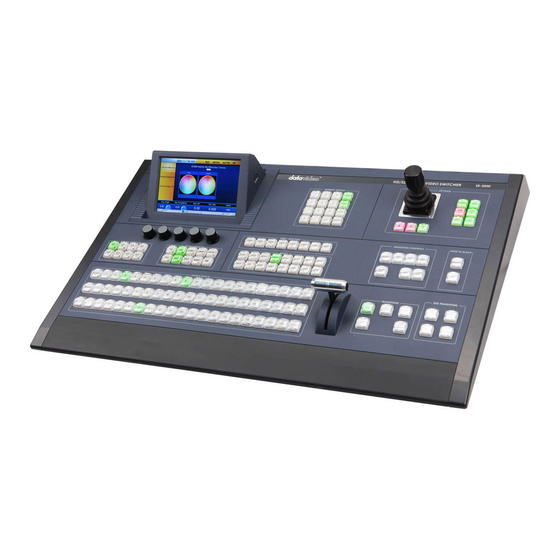
- Page 1 .8 / 16 CHANNEL SWITCHER. SE-3000 Instruction Manual www.datavideo-tek.com...
-
Page 2: Table Of Contents
Main Unit ........................13 Control Panel ......................... 13 Video Connections ......................... 14 SDI Video Inputs ......................14 Setting the Resolution of the SE-3000 ................... 14 DVI Input – Input 8 ...................... 15 Input Channels 9~16 ....................15 Video Outputs ......................... 16 Auxiliary HD-SDI Outputs 1~4 .................. - Page 3 Previewing a selected transition .................... 21 REV and NORM / REV buttons ..................21 WIPE Selection Menu......................22 Wipe ..........................22 Soft Value ........................22 Width Value ......................... 23 Level Value ......................... 23 Soft Balance ........................ 23 Wipe Border ........................23 Colour Palette ......................
- Page 4 The Rotation value ...................... 33 The X and Y values ..................... 33 The Z value ......................... 34 DVE Size ........................34 The Z value of DVE Size ..................... 34 The Soft value of DVE Size ..................34 DVE Border ........................34 Hue, Sat and Luma values ..................
- Page 5 Disclaimer of Product and Services The information offered in this instruction manual is intended as a guide only. At all times, Datavideo Technologies will try to give correct, complete and suitable information. However, Datavideo Technologies cannot exclude that some information in this manual, from time to time, may not be correct or may be incomplete.
-
Page 6: Warnings And Precautions
7. This product should only be operated from the type of power source indicated on the marking label of the AC adapter. If you are not sure of the type of power available, consult your Datavideo dealer or your local power company. -
Page 7: Warranty
Certain parts with limited lifetime expectancy such as LCD Panels, DVD Drives, Hard Drives are only covered for the first 10,000 hours, or 1 year (whichever comes first). Any second year warranty claims must be made to your local Datavideo office or one of its authorized Distributors before the extended warranty expires. -
Page 8: Introduction
Each input channel is also provided with its own Colour Processor or Proc Amp. The SE-3000 Multi Image Preview, via DVI-D or HD-SDI (BNC), can be fed to one or two large format LCD monitor screens, this helps keep the number of required monitors to a minimum. The SE-3000 can also provide four user delegated Auxiliary HD-SDI outputs, as well as providing HD Preview and Program outputs via HD-SDI (BNC) and Component (Y, Pb, Pr). -
Page 9: Features
Features • Up to 16 HD SDI Inputs (8 or 16 Inputs) • Built-in SD-to-HD up converters for up to 4 sources simultaneously (inputs 9~16) • Built-in frame syncs for each input • Dedicated DVI Input (treated as input 8 via a menu option) •... -
Page 10: Main Unit
Main Unit Front Panel The front panel of the SE-3000 Main Unit has a ventilation plate; to prevent overheating please ensure that adequate airflow is provided. The Main Unit also comes with 19” rack mounts already fitted. Rear Panel Control Panel... -
Page 11: Input & Output Connections - Main Unit
BNC connectors will not be present. Units with only 8 inputs can be upgraded to 16 inputs, please speak with your local Datavideo supplier for availability and price. AUX Outputs 1~4 4 user delegated HD-SDI Auxiliary outputs – see page 16. - Page 12 Starting from the Top left corner XLR Balanced Audio Inputs XLR Balanced Audio Outputs TALLY 37 Pin D-Sub connector. See page 51 for more information. RS-422 IN & RS-422 OUT 9 Pin D-Sub connector. See page 54 for more information. RS-232 9 Pin D-Sub connector.
-
Page 13: Control Panel To Main Unit Ethernet Connection
There are two power ON/OFF switches to look at on the SE-3000, one on the Main unit and another on the Control Panel / Keyboard. Start the Main unit first and then the Control Panel. -
Page 14: Video Connections
BNC connectors will not be present. Units with only 8 inputs can be upgraded to 16 inputs, please speak with your local Datavideo supplier for upgrade availability and price. Inputs 9~16 can be used to input Standard Definition or High Definition SDI sources depending on the INPUTS setting for each –... -
Page 15: Dvi Input - Input 8
HDCP protected video. Input Channels 9~16 NOTE: Units with only 8 inputs can be upgraded to 16 inputs, please speak with your local Datavideo supplier for upgrade availability and price. Inputs 9~16 can be used to input Standard Definition or High Definition SDI sources depending on the INPUTS setting for each. -
Page 16: Video Outputs
Auxiliary HD-SDI Outputs 1~4 It is possible to delegate any SE-3000 video input to any one of the four Auxiliary HD-SDI Outputs. These outputs can be really useful as it allows a production team options to place a small HD-SDI monitor (such as the 7”... -
Page 17: Monitor Connections
Multi Image Preview It is possible to operate the SE-3000 with just one or two monitors connected. The Multi Image Preview can be supplied from a combination of the Multi-1 HD-SDI, Multi-2 HD-SDI or DVI-D output. Using one or two of these outputs you can display all inputs plus next source Preview and Program output as well as selected image Stills 1 and 2. -
Page 18: Modifying The Chosen Multiviewer Layout
The bottom of the screen now shows the menu options for MultiViewer and the first option is also called MultiViewer. Tapping on this option in the bottom left hand corner displays the list of 5 layout options. Modifying the chosen MultiViewer Layout It is advisable to have the Multi Image Preview displayed on the Preview monitor(s) first so that you can see the effect of the following settings as you change them. -
Page 19: Modifying The Multi Image Preview Labels
Modifying the Multi Image Preview Labels The 16 input channels, shown on the Multi Image Preview, are initially labelled Input 1 to Input 16 by default. These labels can be changed to suit your needs. For example you may want to use the names of the crew, or label a channel “B-Roll”... -
Page 20: Source Select Button Group
The Transitions group of buttons allows the user to decide how to bring the selected Preset / Next source image to the Program output. The SE-3000 user can decide to use a CUT, MIX, WIPE or DVE transition. In order to use these transition options the BGND (Background) Button needs to be backlit Green in the Transition Controls area of the SE-3000 Control Panel. -
Page 21: Wipe Button
WIPE Button The WIPE button is selected when a 2D wipe effect transition between the selected Program and Preset sources is required. This WIPE effect is produced by then moving the T-Bar manually or by pressing the AUTO TRANS button. DVE Button The DVE button is selected when a 3D DVE transition between the selected Program and Preset sources is required. -
Page 22: Wipe Selection Menu
WIPE Selection Menu There are 30+ different WIPE effects to choose from when using the SE-3000 mixer. Each WIPE transition also has flexible user options to tailor the look of the transition. Example: To select a different WIPE transition, press the WIPE button in the Menus button group of the Control Panel / Keyboard. -
Page 23: Width Value
Width Value This value determines how wide the actual wipe effect is. A low value makes a narrow wipe (A and C move closer together). A large value makes a wider wipe (A and C move further apart). A value of 10 would relate to the wipe being 10% of the width of the screen. -
Page 24: Wipe Shade
Wipe Shade Note: In order for the Wipe Shade effect to work, Shaded Border (Dual Colour) must be selected first as the Wipe Source value – see the previous section Source Control. The Wipe Shade options and values are currently shown along the bottom of the display below. The Wipe Shade Menu allows control of the Wipe Shade Matte. -
Page 25: Dve Transitions Menu
DVE Transitions Menu There are over 80 different DVE Transitions to choose from when using the SE-3000 mixer. Example: To select a different DVE Transition, press the TRANS button in the Menus button group of the Control Panel / Keyboard. Ensure the DVE and BGND buttons are ON see page 20 Transitions Group. -
Page 26: Freeze Menu
Program output. See STILLS Menu on page 27 also. Example: Press the FREEZE button in the Menus button group of the SE-3000 Control Panel / Keyboard. Now look at the Touch Screen Menu Panel. -
Page 27: Stills Menu
Stills Menu The Stills menu allows the user to Grab, Store and Load Uncompressed stills with the SE-3000 Mixer. This feature is generally used after the Freeze menu function, see page 26. The Main unit has two frame stores to which stills can be loaded, and the unit has enough storage space for about 100 uncompressed stills. -
Page 28: Loading An Existing Still From Memory
Loading an existing Still from memory The Still Load Menu allows stills already stored in the SE-3000 to be loaded to either the Still 1 or Still 2 buffer. The Still menu screen (shown above) shows thumbnail pictures of up to 16 saved stills at a time. If there are more than 16 stills stored in the SE-3000 then the Arrow Up and Down buttons on the right can be used to page up or down through the saved stills. -
Page 29: Bus Matte Menu
Flex elements and any CG-350 PC generated graphics or text. Example: Press the MATTE button in the Menus button group of the SE-3000 Control Panel / Keyboard. Now look at the Touch Screen Menu Panel. -
Page 30: Storing And Recalling User Set Ups
Storing and Recalling USER Set Ups The USER menu button allows you to Store and Recall User Set Ups on the SE-3000. If you have standard configurations for your productions then this feature can save you a lot of time re-configuring the mixer after someone else has used it. -
Page 31: Loading A Previously Saved User Set Up
USER / SHOTS BOX area of the SE-3000 Control Panel / Keyboard. A third way to load a saved Set Up is to press the USER button in the Menus area of the SE-3000 Control Panel / Keyboard. Now look at the Touch Screen Menu Panel. -
Page 32: Flex™ Screen Order
Gain or Opacity controls are provided. This keyer is intended to be used with good external key and fill sources such as provided by the Datavideo CG-350 PC. It may be good idea to assign the Flex™ output to an Auxiliary monitor. Then use this full size Auxiliary monitor as a Flex™... -
Page 33: Flex™ Source Select
DVE (PIP) image displayed in the Flex output will also be on its side. Turning the F4 Function Dial next to the Touch Screen on the SE-3000 Control Panel will change the rotation value. Alternatively you could tap on the option within the Touch Screen Panel and then enter a value using the numeric keypad. -
Page 34: The Z Value
The Z value changes the size and position of the DVE (PIP) image based on a zoom function. Increase the value Z and the selected DVE (PIP) image gets smaller and moves towards the centre of the screen. Reduce the Z value and the DVE (PIP) image gets larger and moves out away from the centre of the screen. DVE Size The DVE Size options and values are currently shown along the bottom of the display below. -
Page 35: Dve Crop
DVE Crop The DVE Crop options and values are currently shown along the bottom of the display below. Left, Right, Top and Bottom edge crop values are changed using the F1~F4 Function Dials. As a dial is turned to the right the selected outside edge of the current DVE (PIP) will be cropped or lost. -
Page 36: Flex™ Key And Fill Example Cg-350 Set Up
First ensure the CG-350 software is set up for External key in settings. The Key signal from the Decklink card is then fed to input 15 on the SE-3000 (see diagram below). Tap on Flex™ Keyer Key (Foreground) and then select button 15 from the Aux Bus row on the Control Panel. -
Page 37: Chroma Key Overview
The camera, backdrop and lighting setup will all play an important role in producing the best Chroma Key result. Although the SE-3000 is equipped with excellent keying controls it is always best to start with the best keyable image that your setup is able to produce. -
Page 38: Lighting
Control Panel Button Groups used To Chroma Key with an input source the following button groups are used on the SE-3000 Control Panel. Key 1 and Key 2 Buttons – These 2 keying channels can be used with typical Green or Blue screen set ups. -
Page 39: Chroma Key Quick Set Up
Chroma Key Quick Set Up For this example we will be supplying the SE-3000 with a HD-SDI Green screen foreground video on input 10. We will select the Flex button on the Program source row and this will act as the background video for our key. -
Page 40: Chroma Matte
Chroma Matte This matte sets the centre of colour range that will be used for keying. The Chroma Matte options and values are currently shown along the bottom of the display below. adjustment moves the crosshair + around the colour palette in a clockwise or anti- clockwise direction. -
Page 41: Color Spill
Blue screen to Green screen set up quickly. Luma Key Overview Luma Keying with the SE-3000 allows you to use an image, ideally black and white, to combine two images. The black element of the key image will be replaced by the full colour background image, and the white element will be replaced by the full colour key fill image. -
Page 42: Luma Key Quick Set Up
Luma Key Quick Set Up For this example we will be supplying the SE-3000 with a HD-SDI background feed on input 10. We will select the STILL button on the Aux Bus row and this will be used for Luma keying a static white shape over the video from input 10. -
Page 43: Luma Key - Lift
TOP Button The SE-3000 is able two show Key1 over Key2 or Key2 over Key1 if they are both ON or active. Use the Top button to decide which Keyer will have Priority. See Priority Button on page 47 also. -
Page 44: Mask Menu
Mask Menu The Mask Menu provides controls for the Key Mask function for each of the SE-3000’s keyers whether Chroma or Luma in function. When the user presses the Mask Menu button, the Mask Menu for the currently selected Keyer is displayed. -
Page 45: Keyer Matte
Keyer Matte When Matte is selected in the Keyer Controls button group the current active Key is filled with a Matte colour rather than video. The Keyer Matte option allows selection of this Matte colour. Once the correct keyer has been chosen and set up correctly the Matte function can then be switched on by pressing the MATTE button in the Keyer Controls button group. -
Page 46: Using Key 1 And Key 2
The SE-3000 has several buttons for deciding the on screen order of the Key1/Key2 as well as deciding how the key will enter, or exit, from the production. In the following example we will be using the Transition Controls and Transitions group of buttons on the Control Panel whilst looking at the Preview and Program monitors. -
Page 47: Priority Button
4. If the T-Bar or AUTO TRANS button is used again then the KEY1 button will remain On but the LED above will change back from Green to Red. KEY1 is now removed from the Program output and is active only in the Preview output. 5. -
Page 48: Dsk1 And Dsk2 Quick Set Up
The DSK1 and DSK2 keyers can be used for Linear or Luma keying but cannot be set up for Chroma keying. This is because only Key1 and Key2 are designed for Chroma key use. For this example we will be supplying the SE-3000 with a HD-SDI background feed on input 10. We will select a CG-350 overlay input... -
Page 49: Saving The Dsk1 Dsk2 Set Up
Keyer set up quickly. SE-3000 Keying layers The SE-3000 has 4 dedicated keyers, Key1, Key2, DSK1 and DSK2. All four keyers can be active at the same point in the production. However, these keyers have a layering order over any selected background source. -
Page 50: Looping An External Reference Through The Se-3000
Looping an External reference through the SE-3000 The SE-3000’s built in TBCs can synchronise the input channels internally without the need for external genlock. However, you can choose to loop an external reference through the SE-3000 if you wish using the REF IN and REF LOOP (OUT) BNC connections provided on the rear of the Main unit. -
Page 51: Tally Output
SE-3000 Pin 2 to 32 and 34 must satisfy the following conditions: Dielectric strength: Max. DC 24V Current: Max. 50mA SE-3000 Pin 1 is RESERVED and should be left unconnected. SE-3000 Pins 33, 35, 36 and 37 are Ground. Example of tally connections (Max. voltage:24V) SE-3000 TALLY OUTPUT (Max. -
Page 52: Tally Connection To Two Itc-100 Units
Tally connection to two ITC-100 units It is possible using the diagram below to make a bespoke cable to connect the SE-3000 tally output to 2 x Datavideo ITC-100 units. All 5 connectors on the cabling will have male ends. Below table may also help when producing this cabling. -
Page 53: Features Awaiting Firmware Development
This connector has no function, as yet The SE-3000 features a 9pin D-Sub RS-232 port which is located on the rear panel of the Main unit. This port is not active within the current version of firmware. Please check with your local Datavideo Office for firmware updates and a PDF copy of the control protocol. -
Page 54: Rs-422 In
This connector has no function, as yet The SE-3000 features a 9pin D-Sub RS-422 IN port which is located on the rear panel of the Main unit. This port is not active within the current version of firmware. Please check with your local Datavideo Office for firmware updates and a PDF copy of the control protocol. -
Page 55: Updating The Se-3000 Firmware
Updating the SE-3000 firmware From time to time Datavideo may release new firmware to either add new features or to fix reported bugs in the current SE-3000 firmware. Customers can update the SE-3000 firmware themselves if they wish or they can contact their local dealer or reseller for assistance should they prefer this method. -
Page 56: Checking Firmware Revisions
Checking Firmware Revisions To check the software revision for the SE-3000, press the SETUP button within the Menus area of the Control Panel / Keyboard. Then look at the Touch Screen Menu Panel which should display the information required. Please check with your local Datavideo office if you feel that your unit is not on the latest version of software. -
Page 57: Specifications
Specifications Video format SD (480/59.94i, 576/50i), HD (1080/59.94i, 1080/50i, 720/59.94p, 720/50p) Y:Cb:Cr, 4:2:2 10 bit RGB, 4:4:4 8 bit SDI/HD-SDI Specifications Standard SMPTE 259M-C (270 Mbps, 525/625 component video) High Definition SMPTE 292M (1.485, 1.485/1.001 Gbps) Connector BNC (IEC169-8) Impedance 75 ohms Return Loss HD >15dB(5 MHz to 750 MHz), >10dB(750 MHz to 1.5 GHz) -
Page 58: Service And Support
It is our goal to make your products ownership a satisfying experience. Our supporting staff is available to assist you in setting up and operating your system. Please refer to our web site www.datavideo-tek.com for answers to common questions, support requests or contact your local office below.
Need help?
Do you have a question about the SE-3000 and is the answer not in the manual?
Questions and answers