Table of Contents
Advertisement
Quick Links
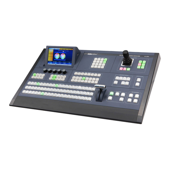
SE-3000
VISUAL QUICK START GUIDE
UPDATED DECEMBER 2012
THIS GUIDE COVERS SE-3000 FIRMWARE VERSION 9.9.9b and ABOVE
PLEASE UPDATE YOUR UNIT BEFORE USING THIS GUIDE.
ALL PREVIOUS VERSIONS OF THIS GUIDE ARE NOW CONSIDERED OUT OF DATE.
NOTE: IF YOU ARE VIEWING THIS COMPUTER ON YOUR COMPUTER AS A PDF, YOU CAN NOW USE THE TABLE OF
CONTENTS TO JUMP TO A SECTION THAT YOU WANT TO SEE. OTHERWISE, PLEASE REFER TO THE PAGE NUMBERS.
For more information about the SE-3000, please visit
www.datavideo.us and visit the SE-3000 product page.
1
Advertisement
Table of Contents

Related Manuals for Datavideo SE-3000


Summary of Contents for Datavideo SE-3000
- Page 1 SE-3000 VISUAL QUICK START GUIDE UPDATED DECEMBER 2012 THIS GUIDE COVERS SE-3000 FIRMWARE VERSION 9.9.9b and ABOVE PLEASE UPDATE YOUR UNIT BEFORE USING THIS GUIDE. ALL PREVIOUS VERSIONS OF THIS GUIDE ARE NOW CONSIDERED OUT OF DATE. NOTE: IF YOU ARE VIEWING THIS COMPUTER ON YOUR COMPUTER AS A PDF, YOU CAN NOW USE THE TABLE OF CONTENTS TO JUMP TO A SECTION THAT YOU WANT TO SEE.
- Page 2 (This page is intentionally blank)
- Page 3 It is quite easy to update the firmware yourself. Note: You must update both the processor and the control panel for the firmware to take effect. If you update only one, the menu functions on the SE-3000 will not work correctly. DOWNLOAD THE FIRMWARE 1.
- Page 4 THE SE-3000 PROCESSOR UPDATE ( Always do this first) 1. Power off the SE-3000 processor and the control panel. Remove the front panel from the processor by unscrewing the four perimeter thumb screws. Insert the USB extension cord that came with the SE-3000 into the USB slot on the circuit board.
- Page 5 3. Power on the SE-3000 processor and the control panel. The latest firmware version number will appear under the control panel’s firmware information on the LCD Press the “SET UP” button in the Menu Button Group on the Screen. control panel to check the firmware version number.
- Page 6 3000 Control Panel. 5. Now remove the USB stick from the SE-3000 control panel, and reboot the SE-3000. This is to verify everything has been updated. After the panel initializes, press the “SET UP” button on the control panel to check the firmware version number.
-
Page 8: Table Of Contents
TABLE OF CONTENTS (GO TO PAGE 7 TO SKIP THE TABLE OF CONTENTS.) 1. INTRODUCTION …………………………………………………7 1.1 KEY FEATURES …………………………………………………7 2. CONTROL PANEL BUTTONS AND MENUS …………………………………………………8 2.1 PROGRAM/PRESET BUTTON CROUP …………………………………………………9 2.2 AUX/BUS DELEGATES …………………………………………………9 2.3 KEYER CONTROL BUTTON GROUP (KEYER CONTROLS) …………………………………………………10 2.4 MENU SELECT BUTTON GROUP (MENUS) …………………………………………………10... - Page 9 3.2.1.4 KEY INVERT CONTROL …………………………………………………18 3.2.2 KEYER MATTE MENU …………………………………………………18 3.2.2.1 HUE SAT LUMA FOR KEYER MATTE …………………………………………………19 3.3 CHROMA MENU …………………………………………………19 3.3.1 CHROMA MATTE MENU …………………………………………………20 3.3.1.1 HUE, SAT,LUM A FOR CHROMA MATTE …………………………………………………20 3.3.1.2 CHROMA MATTE OPACITY …………………………………………………20 3.3.2 CHROMA KEY CONTROL MENU …………………………………………………21 3.3.2.1 KEY ACCEPTANCE CONTROL...
- Page 10 3.7.5 DVI INPUT …………………………………………………32 3.7.6 INPUT REMAPPING …………………………………………………32 3.7.6.1 CROSSPOINT SELECT DIAGRAM …………………………………………………32 3.8 OUTPUTS MENU …………………………………………………33 3.8.1 OUTPUT SOURCE SELECTION …………………………………………………33 3.8.2 MULTIVIEW MODE …………………………………………………36 3.8.2.1 MULTIVIEW OUTS …………………………………………………36 3.8.3 MULTIVIEW MAIN …………………………………………………37 3.8.2.4 MULTIVIEW DIAGRAM …………………………………………………37 3.8.2.5 MULTIVIEW INFO …………………………………………………38 3.9 WIPE MENU …………………………………………………38...
- Page 11 3.11.1 FLEX SOURCE SELECT …………………………………………………48 3.11.2 DVE 1 AND DVE 2 CONTROL …………………………………………………48 3.11.2.1DVE POSITION …………………………………………………49 3.11.2.2 DVE SIZE …………………………………………………49 3.11.2.3 DVE BORDER …………………………………………………50 3.11.2.4 DVE CROP …………………………………………………50 3.11.3 FLEX SOURCE KEYER MENU …………………………………………………51 3.12 USERS MENU (FOR USER SETTINGS) …………………………………………………51 3.12.1 LOAD MEMORY …………………………………………………52...
-
Page 12: Introduction
1. INTRODUCTION This document provides a quick overview of the SE- 3000 buttons, menus and controls. THIS GUIDE IS ALWAYS IN-PROGESS AND IS FREQUENTLY UPDATED. PLEASE CONTACT US IF YOU HAVE MORE QUESTIONS: 562.696.2324 1.1 KEY FEATURES .1 M/E SWITCHER .4 AUX OUTPUT .4 KEYERS (2 IN M/E, 2 DSK) .STORE 100 STILL IMAGES... -
Page 13: Control Panel Buttons And Menus
2. CONTROL PANEL BUTTONS & MENUS 1. LCD TOUCHSCREEN MENU 8.USER SHOTBOX 2. CONTROL KNOBS 9. MENU SELECTION BUTTON GROUP 3. NUMERIC KEYPAD 10. TRANSITION CONTROLS 4. JOYSTICK BUTTON GROUP 11. FADE TO BLACK 5. JOYSTICK 12. SOURCE SELECT BUTTON G ROUP 6. -
Page 14: Program/Preset Button Croup
2.1 Program/Preset Button Group This button group allows you to choose your program & preset bus sources. Available inputs: 1-16 (Video Sources), Black: (Black Background) Matte: (User selected Background Color) Still and Shift. 2.2 Key/Aux Button Group (labeled AUX /BUS DELEGATES ) This button group allows you to configure the key sources for Keyers 1 &... -
Page 15: Keyer Control Button Group (Keyer Controls)
2.3 Keyer Controls Button Group This button group controls the currently selected Keyer or effects that you have set up with Flex Source. Note: When ON is selected in the Keyer Controls button group; your desired keyer effect will be enabled. You must select it to see any of your keyer effects. -
Page 16: Transitions Button Group
2.6 Transitions Button Group This button group controls what your active transition is. MIX – selects the Mix transition. WIPE - selects the Wipe transition. DVE - selects the DVE transition. CUT - performs a cut transition with no effects. AUTO TRANS - performs the selected transition automatically (Mix, Wipe, DVE) in the default Mix and Effect Transition time. -
Page 17: User Shot Box
2.9 User Shot Box Button Group These buttons allow user settings to be saved and recalled with a single button press. Each Button can store 1 User Memory. The memory saves settings that you have created in Flexsource or the whole control panel. -
Page 18: Joystick Button Group
JOYSTICK: When an applicable menu option is open, the joystick controls the rotation and position of certain objects in the DVE Layers of the SE-3000. X, Y, Z: enables or disables the X, Y, Z axis of the joystick, allowing for more precise user control. -
Page 19: Parameter Control Buttons
2.11.6 Joystick When an applicable menu option is open, the joystick controls the rotation and position of certain objects in the DVE Layers of the SE-3000. In certain menus, the joystick can also control parameters like border with, shade size, etc. -
Page 20: Lcd Touch Screen Menus
3. LCD TOUCH SCREEN MENUS This section describes most of the functions of the SE-3000 Touch Screen menus. You can select and adjust controls within each menu by either touching the LCD Screen, using the control knobs below the screen or using the joystick. If you are in a submenu, you can go back to the main menu buy hitting the corresponding menu button found in the ‘MENUS’... -
Page 21: Keyer Control Menu
3.2.1 KEYER CONTROL MENU The Keyer Control Menu allows you to adjust the current Wipe Pattern. The diagonal white line on the grid shows how the lift & gain controls are being applied to the wipe pattern. You can move the end points of the line using the touch-interface on the LCD. -
Page 22: Gain Control
3.2.1.2 Key Gain Control The Gain Control adjusts the key gain. Key gain is the level of intensity that a key color has. For example, if you have selected green as your key color, adding gain will make it a very bright green. -
Page 23: Key Invert Control
3.2.1.4 Key Invert Control The invert option allows the key source to be inverted after lift & gain adjustments have been applied. It has only 2 settings: On and Off. For example, if you have the key source as a basketball with a green background, and the key background as a beach scene, the final key effect will be a basketball on the beach. -
Page 24: Hue Sat Luma For Keyer Matte
3.2.2.1 Hue Sat Luma Controls for Keyer Matte Menu Hue: selects a varied shade of the color chosen. Saturation: Adjusts the richness or vibrancy of a color. Luma: Adjusts the levels of black or white in a color. More of one or the other can make a color appear lighter or darker. -
Page 25: Chroma Matte Menu
3.3.1 Chroma Matte Menu The Chroma Matte Menu allows you to choose your key background color, also known as your Chroma matte). Most commonly this color would be blue or green, but you can select a color of your choice based on your key sources. 3.3.1.1 Hue Sat Luma Controls (Chroma Matte Menu) Hue: selects a varied shade of the color chosen. -
Page 26: Chroma Key Control Menu
( blue or green, or any other color) These adjustments will affect how the SE-3000 generates all keying effects. 3.3.2.1 Key Acceptance Control The Key Acceptance Control determines the spread of hues that are used as background. -
Page 27: Chroma Key Lift Control
3.3.2.3 Chroma Key Lift Control The Chroma Key Lift Control is used to affect the transparency of a Key source when there are very dark areas. If your sources have shadows, the shadows may be keyed out, or look transparent. This is when you would use lift so that the shadows look normal. -
Page 28: Chroma Color Spill Menu
3.3.3 Color Spill Menu Color Spill Menu The Color Spill Menu controls the Suppression or unwanted Chroma Spill from the background onto the foreground. Chroma spill is the area around a subject that is being keyed out. If you have a red apple on a red sheet, some of the apple might be keyed out because it is also red. -
Page 29: Chroma Suppress Control
3.3.3.2 Chroma Suppress Control ( Example coming soon) The Chroma Suppress Control determines what happens to the Chroma Values that are ‘captured’ within the Chroma Acceptance Angle. The Chroma Suppress Control value ranges from 0% to 100%. When set to 0%, and then only the suppression only removes hues that lay only the same axis as the Chroma Hue angle. -
Page 30: Background Supression Control
3.3.3.3 Background Suppression Control This menu controls the background suppression method. For best results, set this control to ‘off’. When BGND SUPPRESS is off, the background suppression is made by the selecting the best Luma (light or dark) value for the Chroma Key Matte (set in the Chroma Matte Menu). -
Page 31: Mask Menu
3.4 Mask Menu The Mask Menu provides controls for the Key Mask function for each keyer. When the user presses the Mask Menu button, the Mask Menu for the currently selected Keyer is displayed. To select a different keyer, select a different keyer from the Aux Bus Delegate. -
Page 32: Matte Menu
3.5 Matte Menu ( Example coming soon) The menu allows the color of the Bus Matte to be set. The Bus Matte is the matte (color) that is selected as a source on the PGM, PVW & AUX source select buses. 3.5.1 Matte Menu Hue Sat Luma Controls The Hue, Saturation and Luma values can also be set using the Control knobs... -
Page 33: Hue, Sat, Luma Controls For Matte
3.6 Freeze( Example coming soon) This menu allows you create frames stores for Inputs 1-16. A frame store is image grabbed from your live input source and “frozen” so you can load it back in as image. 3.6.1 Input selection ( Example coming soon) When the Freeze Menu is selected, buttons for all 16 sources are shown. -
Page 34: Freeze Control And Modes
3.6.2 Freeze Controls ( Example coming soon) Freeze: On/Off This sets the Freeze On or Off Modes: The Freeze Mode can be set to Frame or Field In Field Mode, Field 1 is repeated for both Fields (1 & 2) 3.7 Inputs Menu This menu provides access to the various controls for each input. -
Page 35: Input 1-16
3.7.1 Input 1-16 When the Input Menu is selected, buttons for all 16 sources are shown To adjust an input source, select the appropriate source (1-16) by touching the screen, or using the control knobs. 3.7.2 Input Format and Converter Control ( Only for inputs 9-16) Input Format &... -
Page 36: Input Name
3.7.3 Input Name Input Name Pressing ‘Name’ allows the on-screen name used by the multiviewer to be entered. The Alpha numeric Keyboard allows the name to be entered in a familiar way use ‘Back’ to delete a character. Use ‘Enter’ to when you are happy with the new name. -
Page 37: Dvi Input
For example, if you have 2 chromakey scenes, A and B, you can set the Chromakey parameters once in the built in keyer of the SE-3000, and just reassign A or B as needed. 3.7.6.1 CROSSPOINT SELECT DIAGRAM The crosspoint select diagram shows you where your inputs are being set. -
Page 38: Outputs Menu
ON. 3.8 Output Menu This menu has two functions: 1. Select outputs source for the assignable SE-3000 Outputs (other than AUX). 2. Select the Multiviewer Mode. Please see “How to connect One or Two Monitors with Multiview”, “How to Connect... - Page 39 3.8.1 Output Source Selections As well as the 4 AUX Outputs, the SE-3000 also has the following assignable outputs: Multi 1, Multi 2 (SDI) DVI Output Analog Output The primary Output Menu allows each of these outputs to be independently set to...
-
Page 40: Multiview Mode
3.8.2 Multiview Mode Menu ( Example coming soon) Multiviewer Mode Menu This menu controls the Multiviewer Mode. The Outputs from the Multiviewer are available on the following Outputs from the SE-3000: Multi 1 Multi 2 DVI Output Analog Out 3.8.2.1 Multiviewer Outs ( Example coming soon) - Page 41 3.8.2.2 Multiviewer Diagram The Multiviewer provides the following modes: Single Output Modes: Input 1- 16-16 thumbnail images showing the 16 Primary Inputs Main & Inputs 1 – 8 Two ¼ size Outputs (Main 1 & Main 2) 8 thumbnail images showing primary Inputs 1 – 8 Main &...
-
Page 42: Multiview Main
3.8.2.3 Multiviewer Main Multiviewer Main 1 – 4 Selection: The multiviewer ¼ size Outputs (Main 1-4) can be selected from the following: PGM Output - PVW Output - PGM DSK1 Output - PVW DSK1 Output - Still1 - Still2 - Flex Src Output 3.8.3 MULTIVIEWER INFO 3.8.3.1 AUTO NUMBER 3.8.3.2 LABEL INFO... -
Page 43: Multiview Info
3.8.9.2.5 Multiviewer Info The Multiviewer Info menu allows you to change how the input labels look in your multiviewer output. AUTO NUM: This generates default numbers on all the labels shown. LABEL INFO: Turns the label info on and off TRANSP LABELS: This makes the labels partially transparent so you can see the source video underneath the label. -
Page 44: Soft Control
3.9.1.1 Wipe Select Control The Wipe Select Control provides an alternative way to select the current wipe pattern. Use the control knobs to scroll through the wipe patterns, touch the control & use the numeric key pad to enter the wipe pattern number. -
Page 45: Width Control
3.9.1.3 Width Control This sets the width of the Wipe Border. The value is the width of the wipe edge as a percentage of the screen width I.e. 10% = 10% of the screen width 100% = 100% of the screen width You can adjust this value using the control knobs, or by touching the control and using the numeric keypad. -
Page 46: Soft Balance Control
3.9.1.5 Soft Balance Control This control adjusts the ‘inside’ and ‘outside’ edge softness of the Wipe Border you have selected. If the Soft Balance is set to ‘0.0’ then both the Inside & Outside edges have the same softness, as set by the ‘Soft Control’. If the Soft Balance is set to a positive number, then the inside edge is made softer. -
Page 47: Hue Sat Luma For Wipe Border
3.9.2.1 Hue, Sat, Luma for Wipe Border The Hue, Saturation and Luma values for the Wipe Border can be set using the control knobs, the numeric Keypad, or the joystick. 3.9.2.2 Source Control This control sets the source for the Wipe Border. -
Page 48: Wipe Shade Menu
3.9.3 Wipe Shade Menu The Wipe Shade Menu allows control of the Shaded Color Border of your selected wipe. In order to enable the Dual Color Shaded Border, you must first select it in the ‘Wipe Border Menu’ – see above With the Dual Color Shaded Border Mode enabled, two border colors will now be visible in the Wipe Border. -
Page 49: Shade Soft
3.9.3.2 Shade Soft The softness of the edge between the two Border colors is controlled by the Shade Soft Control. This will only be visible when you have the Dual Color Shaded border enabled. See above. 3.9.4 Wipe Position Menu Certain Wipes, allow the Wipe position to be controlled. -
Page 50: X,Y, Position For Wipes
3.9.4.1 X, Y, Position in the Wipe Position Menu These control the position of the center of the Wipe. You can adjust these values using -the Control knobs Controls -the touch the control, then use the numeric keypad -the joystick X & Y-Axis The position is in terms of screen widths: X = 0.0, Y = 0.0, is the centre of the screen To position the Wipe at the right-hand... -
Page 51: Transition Control
3.10 Transition Control Menu The Transition Control Menu provides controls for the DVE Transition generator. 3.10.1 Main Transition Menu The Main Transition Menu allows you to select your DVE Transitions. 16 DVE Transition icons are displayed at a time. The current DVE Transition will be highlighted with the yellow rectangle. -
Page 52: Transition Select Control
3.10.1.1 Transition Select Control The Transition Select Control provides an alternative way to select the current DVE Transition Use the control knobs to scroll through the DVE Transitions, or touch the control & use the numeric key pad to enter the DVE Transition number. -
Page 53: Flex Source Select
3.11.1 Flex Source Select Menu) The Flex Source Menu allows selection of the sources for the Flex Background, for the two DVEs, and PiP The AUX Bus is used to select these sources The blue buttons on the LCD Menu are used to select which of the sources is delegated from AUX Bus Your options are:... -
Page 54: 1Dve Position
3.11.2.1 DVE Position This menu allows control of the DVE (X,Y,Z) Position in 3D space. It also allows the DVE to be rotated in the Z axis. The DVEs in the Flex Source Processor are 2D DVEs, and do not allow the DVE to be rotated in X, or Y, or have Perspective. -
Page 55: Dve Border
3.11.2.3 DVE Border This menu allows control of the DVE Border. Here the Border Color, Size and softness can be adjusted. 3.11.2. DVE Crop This menu allows control of the DVE Crop The Crop Left, Right, Top & Bottom Crop Edges can be set here. -
Page 56: Flex Source Keyer Menu
3.11.3 Flex Source Keyer Menu This menu configures keyer options and is not a part of Chromakey options. No Lift, Gain, Opacity controls are provided, as this keyer is intended to be used with a good key source from a CG. You will have to use the CG source to correct key &... -
Page 57: Load Memory
3.12.1 Load Memory The Load Memory Menu allows the User Memories stored in the Processor Unit to be loaded into the Processor. The screen shows icons for up to 16 User Memories at a time If there are more than 16 User Memories stored in the Processor Unit the Arrow Up &... -
Page 58: Stills Menu
3.13 Stills Menu The Stills menu allows the user to Capture, Store, & Load Uncompressed stills on the Processor Unit. The Processor Unit has two frame stores (labeled Still 1 and Still 2) to which stills can be loaded into the PRESET or PGM Bus. It also has enough storage space for 100 uncompressed stills. -
Page 59: Grab And Save
3.13.2 Grab & Save The Grab & Save Still Menu allows new Stills be created by capturing images from input sources & saving them to the internal storage in the Processor Unit. ( See “ How to Capture Still Images” for more info) The saving process currently takes about 15 seconds. -
Page 60: Clip Menu
Audio Channel: Digital Audio can carry several channels. SE-3000 allows you to choose 2 channels to embed in the output. Note: Not all features are fully functional; please contact your local Datavideo office or reseller to learn the current status of the audio features. -
Page 61: Audio Mode
3.15.1Audio Mode Audio Mode Sets the type of audio signal being sent out by the switcher 3.15.2 Audio Source Audio Sources sets the source of the audio being sent out of the switcher. If you select Audio Follow, the audio will follow the video sources. -
Page 62: Audio Channel
3.15.3 Audio Channel The SE-3000 also supports 2 channel output, you can select which 2 channels are sending out audio in the SDI stream. 3.16 Set-Up Menu This is the he top level Setup Menu. It shows the firmware version numbers for the Control Panel Software, and the Processor Unit Software. -
Page 63: 0Utput Standard
3.16.1 Output Standard To set the Output Standard for the SE-3000, touch the 'Standard' button, and select the desired standard. 3.16.2 Genlock The Genlock Menu allows control of the Genlock function. By default Genlock is always off. The Genlock Source can be selected using the Source Select button, and you can turn it on or off by touching “ENABLE”... -
Page 64: Language Selection
3.16.3 Language Selection The Language used on the Control Panel can be selected using the Change Language Menu. To select the language to be used, press the Language Button, and select the desired language from the list. 3.16.4 Engineer Menu This menu will only contain options for Debug purposes.
Need help?
Do you have a question about the SE-3000 and is the answer not in the manual?
Questions and answers