Table of Contents
Advertisement
Advertisement
Table of Contents

Related Manuals for Datavideo SE-600


Summary of Contents for Datavideo SE-600
- Page 1 .Digital Video Switcher. SE-600 Instruction Manual www.datavideo-tek.com...
-
Page 2: Table Of Contents
Contents Warnings and Precautions ....................5 Warranty ..........................6 Disposal ................................6 Packing List ..............................6 Product Overview ......................7 Features ................................7 Connections & Controls ....................8 Keyboard Overview ............................8 Rear Panel ..............................8 Rear Panel Connections ..........................9 DVI-D Multi-Image Preview .................... - Page 3 7: MULTI. IMAGE ............................16 8: SYSTEM ..............................17 9: STORE RECALL & UPDATE ........................17 10: RESET DVI_IN ............................17 SE-600 Video Layers ......................18 PIP – Picture In Picture function ..................19 PIP Setting ..............................19 Choose your PIP sources ..........................19 Setting the size of each PIP Image .......................19 Setting the Position ............................19...
- Page 4 Further advice on the content of this manual or on the product can be obtained by contacting your local Datavideo Office or...
-
Page 5: Warnings And Precautions
7. This product should only be operated from the type of power source indicated on the marking label of the AC adapter. If you are not sure of the type of power available, consult your Datavideo dealer or your local power company. -
Page 6: Warranty
Certain parts with limited lifetime expectancy such as LCD Panels, DVD Drives, Hard Drives are only covered for the first 10,000 hours, or 1 year (whichever comes first). Any second year warranty claims must be made to your local Datavideo office or one of its authorized Distributors before the extended warranty expires. -
Page 7: Product Overview
A Multi-image preview output provides combined Source, Preview and Program screens to one monitor. Other features include an Audio Peak Meter, a Clock and a dual Logo store. The SE-600 enables you to switch seamlessly between video and audio sources and blends high-quality digital content on the fly, even without external gen-lock, thanks to a built in time base corrector. -
Page 8: Connections & Controls
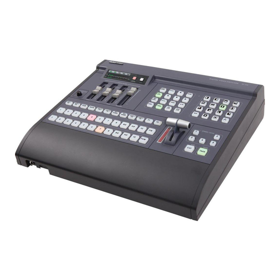
Connections & Controls Keyboard Overview 1. Audio Peak Meter T-Bar 2. Audio Mixer 10. Cut Button 3. Headphone Volume Control 11. Take Button 4. Aux Source Selection 12. Speed / Level selection 5. Main Source Row 13. Transition selection 6. Sub Source Row 14. -
Page 9: Rear Panel Connections
Rear Panel Connections DVI Inputs DVI-D (Input 7) digital signal input connector. DVI-I (Input 8) digital or analogue signal input connector. Resolutions of 1280x1024 @ 60Hz or 1024x768 @ 60Hz should be compatible depending on your graphics card or computer. Composite (CVBS) Inputs Composite video input: takes a BNC connector from the composite output of a VCR, camera, DVD player, etc. -
Page 10: Dvi-D Multi-Image Preview
Preview (PST_SUB) and one for the Program (PGM_MAIN) outputs. In between the PST and PGM images is the SE-600 Status Display and below it the Settings Display. When the Settings Menus are not in use you will see audio peak meters here instead as shown above. -
Page 11: Keyboard Controls - Video Switching
Keyboard Controls – Video Switching Main Source and Sub Source Rows The Main Source Row of buttons is the active channel, this is the Live output. The active channel will appear as the Program Output (PGM). You can switch or CUT from one source to another directly on the Main Source Row. You will see the PGM Output change as you press different keys along this row of buttons. -
Page 12: Keyboard Controls - Video Transitions
Keyboard Controls – Video Transitions Transition Selection The SE-600 features 14 programmable wipe patterns and an A/B dissolve or fade. All wipes can have an optional colour border applied, and can be set to one of five preset speeds. The active transition, speed, border width and colour are confirmed in the Multi-Viewer Status Display. -
Page 13: Keyboard Controls - Video Effects
Keyboard Controls – Video Effects SETTING BUTTON This button is used to enter the SE-600 configuration and settings menus. The menu options are displayed on the DVI-D based Multi-Image Preview output. Press the up, down, left, or right arrow buttons to navigate the menu choices or to change values. -
Page 14: Keyboard Controls - Special Effects
Item by item reset function AUX Source Selection There are four Composite Auxiliary outputs on the rear of the SE-600. Two AUX1 outputs and two AUX2 outputs. It is possible to assign either a source input, background colour, Preview (PST) or Program (PGM) to these outputs. -
Page 15: Settings Menus
PST image of the Multi-image Preview. It is possible to use the input from a computer with CG-100 software to create a text or graphic overlay on top of the SE-600 PST or PGM video. It is also possible to use a video input as a keying source to create a pleasing or original video effect. -
Page 16: 4: Logo
Multi-image Preview. A computer designed logo or station bug file can be saved to an SD card and loaded into the SE-600 memory. The Logo can then be assigned to one of two buttons and overlaid on top of the Program output. -
Page 17: 8: System
8: SYSTEM This menu option allows the user to set up the SPEED KEYS for transition duration values, Keyboard backlight brightness and define the use of GPI/O port on the rear of the mixer. Press the SETTING button and then use the arrow buttons to highlight the SYSTEM item ... -
Page 18: Se-600 Video Layers
SE-600 Video Layers The SE-600 is a Standard Definition Digital Video Switcher and as well as mixing video and audio sources it has additional functions such as Picture In Picture (PIP), CG LUMA KEY and LOGO. Before attempting to use the SE-600 PIP, CG LUMA KEY and LOGO functions it may help to first understand the order of the video layers at the SE-600 Program (PGM) outputs. -
Page 19: Pip - Picture In Picture Function
PIP – Picture In Picture function The SE-600 Picture in Picture function allows you to place one or two smaller PIP images over a chosen full size background image. The smaller PIP images can be set to one of two predefined sizes and positioned almost anywhere within the Preview/Program screen area. -
Page 20: Preparing The Pip Output In The Pst_Sub Window
Preparing the PIP output in the PST_SUB Window When preparing the PIP display output you will want to see it in the Multi-Image Preview PST_SUB output. To achieve this you need to press the PIP button on the lower Sub Source row of buttons first. No PIP Windows? If you can only see your chosen background image but no smaller PIP windows in the PST_SUB image then you need to activate one or both PIP windows. -
Page 21: Cg (Luma Key) Function
DVI, and replace the white or black parts of this image with the video from another source. It is also possible with the SE-600 to keep the pure white and black parts of the key source image and only key video using the greyscale part in between pure white and black. -
Page 22: Setting Up A Luma Key Overlay With Powerpoint
Setting up a Luma Key overlay with PowerPoint The SE-600 has 8 inputs. Inputs 7 & 8 are DVI and these can be used to connect a DVI-D cable from a computer. The computer graphics card will need 2 output connectors, one for the PC monitor and one DVI connection to go to input 7 or 8 on the SE-600. -
Page 23: How To Set Up A Window Matte For Luma Keying
Overview The SE-600 can display one or two logos in any location on the screen. If you want a larger logo it is possible to create two halves and combine them on the screen. The logos when activated will only show in the PGM_MAIN window or on Program outputs so you need to plan, prepare and set up the logos well in advance of the start of the production. -
Page 24: How To Replace The Sample Logos
For the SE-600 to recognise the logos they must be called logo1.bmp and logo2.bmp. The Logos are transferred to the SE-600 on an SD Card. This is inserted into the SD card slot on the front edge of the SE-600 keyboard. -
Page 25: Setting Up A Logo
POSITION Y sets the vertical position (up/down) and POSITION X sets the horizontal position (left/right). Luma Keying with the Logo Function With the SE-600 it is possible to Luma Key in two ways, either with the CG (LUMA KEY) function or with the Logo function. -
Page 26: Video Input Adjustment
Video Input Adjustment It is possible to adjust the Composite or DVI video signals within the Datavideo SE-600 switcher. However, it is always better to try to produce the best video signal possible from the input equipment first. For example, if the connected video equipment is a live camera then it should be possible to white balance the camera and reset its exposure level after any stage lighting has been set up. -
Page 27: Main Video Outputs
MAIN Video Outputs The SE-600 has a number of video outputs. The video outputs labelled MAIN are four assignable BNC connectors on the SE-600 rear panel. These four BNC connectors which supply the mixed Program (PGM_MAIN) pictures can be set up as: A group of three BNC connectors for Component (YUV) output plus one spare BNC for Composite (CV) output. -
Page 28: How To Assign Main And Sub Source Buttons
How to assign Main and Sub source buttons The video inputs on the rear of the SE-600 are numbered 1 to 8. The first six are Composite (BNC) connectors and inputs 7 and 8 are DVI inputs. If we are using all of the video inputs then this numbering scheme works well and matches the default video assignments of the Main Source and Sub-Source rows of buttons on SE-600 keyboard. -
Page 29: Audio Mixer Function
In fact, it may even help prevent damage to your equipment, your hearing and even protect the audio circuits of the SE-600. So if you are new to audio mixing this information should be very useful. -
Page 30: Not All Microphones Are The Same
So it helps to understand the line and mic switches associated with the balanced XLR audio inputs on the rear of the SE-600 mixer. -
Page 31: Keyboard Controls - Audio
Audio Monitor Button Use the Headphone output on the front edge of the SE-600 keyboard to accurately monitor any of the sources CH1, CH2, RCA or “Master” output. Repeated presses of the Audio Monitor button cycle an LED through the monitoring choices just above the Audio Peak Meter. -
Page 32: Audio Mixer Menu
Options 1 and 2 of the Audio Mixer Menu allow you to produce a 1KHz test tone at a set level. This test tone overrides any audio already at the SE-600 audio outputs. This can be useful when setting up equipment such as recorders and speakers before a production starts. -
Page 33: Audio Follows Video Selection (A+V)
Audio follows video selection (A+V) The Audio Mixer Menu is split across two pages. In order to see the second page of options use the arrow keys to highlight NEXT PAGE and then press ENTER. The following screen will then be shown between the PST and PGM images on the Multi-Image Preview output. -
Page 34: Changing The Multi-Image Preview
Changing the Multi-Image Preview The appearance and some of labels on SE-600 Multi-Image Preview can be changed by the user. When the SETTING button is pressed in the EFFECTS area of the 1: COUNT_DOWN_TIME SE-600 keyboard the Main Menu list, shown left, is displayed between 2: PIP the PST and PGM images on the Multi-Image Preview output. -
Page 35: Gpi / Gpo Connections
The GPI interface is a 3.5mm Jack Socket which is situated on the rear panel of the SE-600. Contact closure between the Outer and Inner contacts on the jack plug will trigger a user selected event. -
Page 36: Store And Recall Function
Store and recall function The SE-600 has the ability to store your usual settings to one of three back up memory points within the unit. This can be handy if you find someone has changed your usual set up and you need a quick way to get back to your stored standard set up. -
Page 37: Se-600Tally Outputs
SE-600Tally Outputs The SE-600 has two Tally Output ports, one for channels 1 ~ 4 and the other for channels 5~8. These ports provide bi-colour tally information to a number of other Datavideo products, such as the ITC-100 8 Channel Talkback system and LCD Monitors. -
Page 38: How To Update The Firmware
How to update the Firmware From time to time Datavideo may release new firmware to fix reported bugs in the current SE-600 firmware or to add a new feature. Customers can update the SE-600 firmware themselves if they wish or they can contact their local dealer or reseller for assistance should they prefer this method. -
Page 39: Optional Dv And Sdi Output Board
Optional DV and SDI output board The SE-600 can be supplied with, or without, an optional DV and SDI board fitted. Please check with your dealer which model you should have. The DV and SDI board has two 6pin IEEE-1394 DV ports and two SDI BNC connections. All connections on this board are outputs. -
Page 41: Rs-422 Protocol
RS-422 Protocol The SE-600 can be controlled remotely by computer using the RS-422 protocol. This is a professional feature that requires programming and or prior experience. Your dealer or local Datavideo office can supply you with a copy of the separate RS-422 Protocol document which has been written with experienced system integrators and programmers in mind. -
Page 42: Specifications
CVBS x2 and Y/C or CVBS x1 and YUV x1 ˙Aux (1) outputs: CVBS x 2 ˙Aux (2) outputs: CVBS x 2 Outputs If SE-600 fitted with Optional DV & SDI card ˙DV25 Outputs: IEEE-1394 x2 (Optional) ˙SDI (BNC) x2 (Optional) Analogue Y.U.V. Video (SONY Betacam standard) -
Page 43: Service And Support
It is our goal to make your products ownership a satisfying experience. Our support staff are available to assist you in setting up and operating your system. Please refer to our web site www.datavideo-tek.com for answers to common questions, support requests or contact your local office below.
Need help?
Do you have a question about the SE-600 and is the answer not in the manual?
Questions and answers