Datavideo SE-800 Instruction Manual
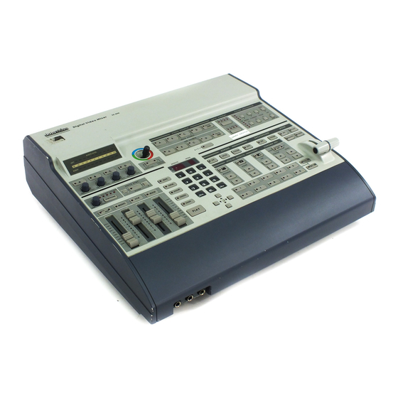
Digital video switcher
Hide thumbs
Also See for SE-800:
- Upgrade instructions (11 pages) ,
- Quick user manual (3 pages) ,
- Quick manual (2 pages)
Table of Contents
Advertisement
Advertisement
Table of Contents

Subscribe to Our Youtube Channel
Related Manuals for Datavideo SE-800


Summary of Contents for Datavideo SE-800
- Page 1 Digital Video Switcher SE-800 INSTRUCTION MANUAL Http://www.datavideo-tek.com...
-
Page 2: Table Of Contents
Introduction… … … … … … … … … … … … … … … … … … … … … … … … … .… … … … … … … … … … … 5 Introduction Product overview DV format: advantages and limitations What is a switcher? What is a frame synchronizer? Possible applications Product Registration... - Page 3 Using Transitions… … … … … … … … … … … … … … … … … … … … … … … … … … … … … … … … 35 Selecting a Transition: Fade, Wipe, Zoom Playing a Transition Manually Auto-play Using the Keypad to customize a transition...
-
Page 4: Warnings And Precautions
7. This product should only be operated from the type of power source indicated on the marking label of the AC adapter. If you are not sure of the type of power available, consult your Datavideo dealer or your local power company. -
Page 5: Radio And Television Interference
TV reception, and may void the user’ s right to operate this equipment. Declaration of Conformity Model Number: SE-800 Trade Name: Datavideo Responsible: Datavideo Corporation (USA) Address: 12300-U East Washington Blvd., Whittier CA 90606, USA Telephone: (562) 696-2324 This device complies with Part 15 of the FCC Rules. -
Page 6: Introduction
You might want to immediately take a look at the Quick Start section on page 15 for a quick overview. Product Overview Now you can shoot, mix, and edit, all within the DV25 format. Datavideo SE-800 is a 4 input channel digital switcher, featuring four multi-format inputs for each channel (your choice of DV (DV25), Component YUV, S- video (Y/C), or Composite video) and an SDI Overlay port that will allow you to use your PC as a character generator and/or graphics source. -
Page 7: What Is A Frame Synchronizer
The SE-800 has a full frame synchronizer (also known as a time base corrector or TBC) at its Main and Sub Source inputs (2 total) to insure switches without distortion and smooth, well-regulated video at its output. In addition to its digital memory, a TBC also has controls that affect the look of the video that passes through it. -
Page 8: Tech Support
Tech support Datavideo maintains three offices worldwide to support this and other products. Datavideo Technologies Co., LTD. 7F, No. 352, Sec. 2, Chung Shan Rd Chung Ho City, Taipei Hsien, Taiwan R.O.C. Tel: 886-2-2246-7979 Email: info@datavideo.com.tw Datavideo Corporation USA 12300-U East Washington Blvd. -
Page 9: Installation, Connections, Set Up
Installation, Connections, Set up Rear Panel Connections 1c 1d 1e 1. Video inputs, Channels A, B, C, D. 1a. S-Video (Y/C) input 1b. Composite video input (BNC) 1c. Monitor output, composite video (BNC) 1d. Component (YUV) video inputs (BNC) 1e. DV input (Firewire 6-pin with cable power 14.5VDC) 2. - Page 10 2. SDI Overlay In: BNC connector for bringing in a Serial Digital video signal from a computer graphics card, which will automatically be overlaid on the output mix of the SE-800. For more information, see Using SDI, page 14. 3. SDI Overlay Out: BNC. For more information, see Using SDI, page 14.
-
Page 11: Connecting Video Sources
Composite video out: BNC connector, typically connected to a program monitor. d. Black Burst out: BNC connector carrying a black burst signal (derived from the SE-800’ s internal TBCs), used to provide a sync source to any video devices connected to the SE-800 that may require sync for proper operation. -
Page 12: Some General Notes On Installation
Controls and Operations page 22 and Output and Monitor, page 13. Some General Notes on Installation There are a few other things to be aware of when you are installing and integrating the SE-800. Please make sure you have read the Warnings and Precautions section on page 3. -
Page 13: Power Up State
Connecting Audio Sources The SE-800 uses 2 kinds of plugs for audio connections: RCA and 1/4 inch jack plugs. There are lots of different names for these plugs. Fortunately for us all, they are not easily confused in the size and shape... -
Page 14: Outputs And Monitor
Take a look at the Sample Applications, page 15 for some examples. While all the outputs of the SE-800 are very high quality, keep in mind that the video quality of the various formats, in descending order, goes like this: SDI (serial digital), Y.U.V. (analog component), DV, Y/C (S-video), and composite. -
Page 15: Gpi Trigger
A GPI (General Purpose Interface) trigger is connected here by means of a mini plug (1/8”). This device allows you to make the SE-800 do certain things at the specific moment you press the trigger, such as making transitions and effects happen. For more information on what you can do with the GPI Trigger, see Using Transitions, page 35, and Using Effects, page 41. -
Page 16: Quick Start
Do this: Connect the recorder, input, and monitor devices as shown. Turn on all peripherals, then power up the SE-800. You can tell that the initialization cycle has completed when the Main Video Source LEDs (4.) and others are lit. - Page 17 Do this: Connect the recorder, input, and monitor devices as shown. Turn on all peripherals, then power up the SE-800. You can tell that the initialization cycle has completed when the Main Video Source LEDs (4.) and others are lit.
- Page 18 Do this: Connect the recorder, input, and monitor devices as shown. Turn on all peripherals, then power up the SE-800. You can tell that the initialization cycle has completed when the Main Video Source LEDs (4.) and others are lit.
- Page 19 Audio meters Audio input selectors and level controls Joy stick and mode selector Main Video source selector Sub video source selector Audio follow video switch Input format selector Color processor Border control 10. Background control 11. Mode selectors 12. T-Bar 13.
-
Page 20: Selecting Video Input Formats And Adjusting Audio Levels
We’ ll save the speech on how important monitoring is for another section. Suffice it to say that without reliable video and audio monitors, you won’ t be able to tell what’ s what in your mix. The SE-800 provides the ability to easily and reliably monitor video and audio at both the input and output stages. -
Page 21: Cutting Between Sources
Effects There are two places on the SE-800 where you can add effects: in the Special Effects section (14- 16.) and in the Auto plays section (20.). Some of these work on a single source, and some need two sources to work. - Page 22 Border control (9.), then trying different sizes, colors, and softness levels. For more information, see Using Effects, page 41 This concludes our Quick Start section. By now, you should have a good idea of some of the capabilities of your new SE-800 Digital Video Switcher!
-
Page 23: Controls And Operations
Controls and Operations SE-800 Front Panel 1. Audio meters 2. Audio input selectors and level controls 3. Joy stick and mode selector 4. Main Video source selector 5. Sub video source selector 6. Audio follow video switch 7. Input format selector (Setup video) 8. - Page 24 1. Audiometers: LED style meters, which show the signal strength at the Audio Output. The signal they measure is determined by the sources selected by the Audio Bus selectors (22.) and the levels set by the Faders (21.). The LEDs turn red at +9 dB to indicate clipping distortion.
-
Page 25: Video Source
6. A+V: Audio follow video switch. When this button is engaged (you’ ll know it is engaged because the LED is lit), the audio associated with a selected input source automatically follows the video through the dissolve. When the button is inactive, audio must be switched manually. - Page 26 11. Mode: selects the T-Bar operating mode of the SE-800, between Video (default), Audio, GPI, and Play. For more information, see Mode select in the Using Transitions section, page 35, and Mode select in the Using Effects section, page 41.
- Page 27 16. Mosaic: when engaged (and the Mosaic LED is lit), this turns the selected Main Source Video into a mosaic of colored squares. There are 8 mosaic patterns to choose from, selected by repeated presses of the up and down buttons. The effect can be applied to the whole image or one of two window sizes, which can be positioned anywhere on the screen.
- Page 28 21. Faders: sliders to control audio levels for the Main audio output mix. Each is active when the LED on the Audio bus selector button (22.) above it is lit. For more information, see Audio Inputs, Levels, and Meters, page 32. 22.
-
Page 29: Video Source
Tech note: The frozen image is a function of how the time base corrector (TBC, a.k.a. frame synchronizer) works. The SE-800 has a TBC at the Main Video Source and the Sub Video Source inputs. Their purpose is to stabilize the video signals as they come into the switcher, and to synchronize their timing so that they can be switched and otherwise combined with no disruption to the video signal. -
Page 30: Input Formats
YUV=analog component video (Betacam, DVCPro, DVCam, etc.) Settings made in this section are “remembered” by the SE-800 after you power down the unit. In other words, these settings remain in effect until they are changed or the Reset All button is pressed (see Color Processor below). - Page 31 (Brightness, Contrast, Color, and Tint) are pressed. U stands for Unity, or perhaps Unchanged. In either case, it shows that the signal passing through that particular control is being neither boosted nor cut. To see the settings for another control, press either one of that control’ s buttons. To change the settings, press the up and down arrow buttons.
-
Page 32: Rgb Color Correction
Appendix: Monitor Calibration, page 55. Settings made in this section are “remembered” by the SE-800 after you power down the unit. In other words, these settings remain in effect until they are changed or either the Reset or the Reset All button is pressed. - Page 33 Audio Input Level Calibration Procedure The first step in setting up the audio for a session with your SE-800 consists of adjusting the levels on each channel you will be using. To do this, first make sure A+V is not selected. If it is, you will only be able to adjust the audio for whichever channel is selected on the Main Video Source bus.
- Page 34 These faders correspond to the selector buttons above and control the relative volume of each input in the master output as well as the master output level. They are called faders because they are used to decrease (rather than increase) the signal levels to make a balanced and pleasing mix. When they are set at Unity, at 6, they pass the audio signal through at the same level it was at when it entered this bus.
- Page 35 When engaged, this control allows you to compensate for delays in the video as it travels through the various components, processors, and converters of the Switcher, so that the video maintains sync with the audio. This control is adjustable from +3 frames (audio advanced) to –19 frames (audio delayed) to the main Audio bus at the “Video”...
-
Page 36: Using Transitions
2 of this manual: SE-800, an Observer’ s Manual.) The SE-800 can do 4 kinds of transitions: cut, fade, wipe, and zoom. The cut is a simple switch from one input source to another, and can be accomplished by selecting a source on the Main Source Bus, and then selecting a second one. - Page 37 Auto-play The Take-button automatically plays the selected transition between the selected sources. Parameters (effect variation and speed) are displayed in the windows above the Keypad. See the next section below for more information. Using the Keypad to customize a transition The windows at the top of this section display parameter data relating to the selected effect.
- Page 38 Mode selects and use The default mode for the SE-800, and the one you will use most often, is Video. In Video only mode (Video LED is lit), the T-Bar operates as expected and as described everywhere in this manual.
- Page 39 Zoom off to lower left Zoom on from lower left Zoom off to lower right Zoom on from lower right Zoom off to center Zoom on from center Wipe (works in conjunction with Border controls except Soft): Horizontal wipe, top to bottom Horizontal wipe, bottom to top Vertical wipe, left to right Vertical wipe, right to left...
- Page 40 Horizontal compress, top to bottom Horizontal compress, bottom to top Vertical compress, left to right Vertical compress, right to left Right angle wipe off, lower right to upper left Right angle wipe on, upper left to lower right Right angle wipe off, lower left to upper right Right angle wipe on, upper right to lower left Right angle reveal, upper right to lower left Right angle reveal, lower left to upper right...
- Page 41 Right angle reveal, upper left to lower right Right angle reveal, lower right to upper left Vertical wipe, left and right to middle Vertical wipe, middle to left and right Horizontal wipe, top and bottom to middle Horizontal wipe, middle to top and bottom Vertical compress, left and right to middle Vertical expand, middle to left and right Horizontal compress, top and bottom to middle...
-
Page 42: Effects
Using Effects The SE-800 is capable of producing a wide variety of digital effects. These fall into 2 categories: single channel and dual channel effects. Single channel effects are produced on the source selected in the Main Video Source bus and need no second video input. -
Page 43: Freeze
Freeze This effect freezes the incoming video, as selected on the Main Video Source bus. Simple as that! There are no parameters, no variations. Press the button once, and the video freezes, press it again, and it returns to the selected source in full motion. The Freeze effect is single channel, and can work in conjunction with any transition. -
Page 44: Effects: Paint
1 = large window is the affected area 2 = small window is the affected area To position the Mosaic window effects, press the button under the Joystick until the LED for Position Control is lit. Then you can use the joystick to position the effect in real time, anywhere on the screen. When you exit the effect, the position will be remembered as long as the Position Control LED is lit. -
Page 45: Border
Border These controls are used in conjunction with the Picture in Picture Effect and the Zoom and Wipe transition only, and can only be activated when either the Picture in Picture or Zoom control is active. With the On button’ s LED lit, parameters for Style, Color, and Border Softness can be set by pushing the appropriate button. -
Page 46: Chroma Key
Sample applications We figured, being practical minded, that the best way to show off what the SE-800 can do is to give you some examples of how it could be used in real life situations. If you haven’ t yet looked at the Quick Start section please do so now. -
Page 47: Production Studio: Cable News/Weather Show
The point of this set up is to produce and record, in one pass, a multi source program. Personnel required for this operation, aside from the on camera talent, are 2 camera operators, a sound mixer, and the SE-800 operator, presumably you. This set up could easily be modified to produce a lecture/demonstration, cooking show, or special effects segment, for example. - Page 48 DV tape, which means that we can bring the tape back into a post-production environment and add titles and/or graphics to it by using the SDI Overlay input on the SE-800 and video card that has that capability, and record that operation to DV tape again with no generational signal loss.
-
Page 49: Live Event Switching: Club Vj
It is not your mother’ s light show any more. Advances in technology, specifically the SE-800, have dramatically widened the performance possibilities, increased the ease of set up and use, and decreased the cost. -
Page 50: Troubleshooting
These set ups can be modified for use in a lot of different situations. Please let us know how you are using your SE-800, and take a look at the web site to see how others are using their SE-800s! -
Page 51: Glossary Of Terms
Appendix Glossary of Terms analog video: a video signal that is recorded and played back using changes in magnetic levels recorded on a tape or disk, e.g., the video we see when we watch a VHS videocassette. MISCation: a video or film sequence that gives the illusion of motion by presenting a series of images or photographs. - Page 52 frame synchronizer: a digital buffer that stores a frame of video, compares the sync information to a reference, and releases the frame at a specific time to adjust for timing errors. glossary: a list of difficult or specialized words for reference. GPI: General Purpose Interface, a simple trigger device.
- Page 53 (cameras, recorders, switcher, etc.) in a video system. THD (Total Harmonic Distortion): Of a signal (most often audio), the ratio of the sum of the powers of all harmonic frequencies above the fundamental to the power of the fundamental, usually expressed in dB.
-
Page 54: Tech Notes (Video Standards, Formats, And Quality; Monitor Calibration)
Tech Notes Books are written about many of the topics below, large and complex books. Look for them if you want more information than what we have presented here. What we want to do here is to provide a bit more in depth information, deeper background, on some relevant topics, and give you a framework for further technical investigations. -
Page 55: Monitor Calibration (Procedures, Test Patterns/Bars)
The point of all this technical information is ultimately to help you to make high quality video: video that looks good and serves the purpose for which it is made. But how do we know if the video is of high quality? And what does that really mean? There are certain technical standards that video must meet simply in order to be viewable on a monitor. - Page 56 But, if you don’ t have a waveform monitor/vector scope to adjust incoming video, you can make those adjustments by eye, using the SE-800’ s color processing controls, now that you have a properly calibrated program monitor. The process for each input channel will be very similar to the process we just used to calibrate the program monitor, except we were adjusting the controls on the monitor, and now we will be adjusting the controls on the SE-800.
- Page 57 For each input you plan to be using, have a valid signal and adjust the Color Processor controls on the SE-800 in this order: 1. Set contrast to midpoint; turn color all the way down so that the image is gray;...
-
Page 58: Signal Flow Schematic
EPE:EEPROM check error. WPE:write EEPROM error. EnE:video encorder error. brE:black_burst encoder error LdE:Load Program error. “U”Flash:Internal Link error Note: Please power the SE-800 off & on to reset the system if any error code is displayed on LED display... -
Page 59: Specifications
Full Screen Position Control By Joystick with 2 Rectangular Mosaic size options Instant Playback Keys F01 to F30, 30 Programmable keys RS-232 Data Control Port Connecting Datavideo RMC-90 Remote Control Panel Connecting PC RS-232 for remote control GPI Control Remote Trigger Control with Pre-programmed effects in Sequence from F01 to F30... - Page 60 Digital Y.U.V. Interface SDI (SMPTE 259M-C 270Mbps) Color Processing Brightness +/-10% Contrast +/- 3dB Color +3/-10dB R.G.B. White Balance: +/- 10 Degrees Video Bandwidth Component 5.2 MHz S (Y/C) 5.0 MHz Composite5.0 MHz DG, DP +/- 3%, 3 degrees Signal/Noise Ratio: Video >...
-
Page 61: Useful Accessories
Useful Accessories from Datavideo Datavideo TLM-404 4”x4 TFT LCD panel Datavideo TLM-404 is a 4x4” TFT LCD monitors, 2U height design for standard 19" rack mount. NTSC/PAL video format auto recognition with video pass through 75-ohm self-terminated video output connector. The "AUX" input provides options for external format converters such as SDI and DV input converter. - Page 62 Tally control for the Datavideo TLM-404 LCD panels and three GPI triggers to control Datavideo DV Bank. Datavideo DV Bank Native DV recorder and GPI Trigger cable Built-in 120GB HDD for 9 hours native DV backup recording DV Bank is the industry-standard, stand-alone...
-
Page 63: Datavideo Bac-03 Balanced-Unbalanced Audio Converter
SE-800 or send the SE-800 output to several other DV Sources. One input to five channels output DV-DA (VP-332) Please check website (www.datavideo-tek.com) for the most up to date list, descriptions, and pricing of accessories for the SE-800. UNBAL to BAL output... - Page 64 9) is Vin (V5.0) related function. You may change it accordingly. The new firmware enables new features as below: 1). RS-232 interface control to SE-800 (For the Datavideo RMC-90 Remote control panel or for PC RS-232 interface control) 2).
- Page 65 2). On performing an effect transition, the selected A, B channel’ s LED indicators on Main Source will both be turned on. 3). During SETUP the video format type for channel A, B, C, D, you may select the main source output accordingly to enable the video output to TV display.
- Page 66 5). Selectable AGC ON/OFF control Procedure to turn Off/On the video input Auto Gain Control (AGC) S1. Click on Setup button to select channel A, B, C or D S2. Select Effect: “02” and “Enter” S3. Click on the “SPD” key to toggle speed LED display “Y”...
- Page 67 7). Internal Chroma- Key ON/OFF control To turn Off/On internal Chroma-key function for application of EXT SDI CG overlay. S1. Click on SETUP button to cycle 4 channels LED on. S2. Select Effect: “02” and “Enter” S3. Click on the “SPD” key to toggle on speed LED display “Y”...
- Page 68 SE800 RS-232 Remote Control Command Released date: Dec-01-2003 1 Physical layer 1.1 Control output format: RS-232C Communication rate: 57600 BPS Data format: 8 bits serial, LSB first, 1 start bit, 1 stop bit, odd parity 2. Data link layer 2.1 Frame format Header Length Data0 Data1 Data2 Data3 1) Header...
- Page 69 3. Application layer The application layer designates the command structure and contents. 3.1 Command data format Command Operated group 1) The command group 03h(base 16) = SE800 control command 2) The operated refer to section 4. 3.2 Return data format Command parameter status...
- Page 70 5. The SE800 control key code 01h = key_main_A 02h = key_main_B 03h = key_main_C 04h = key_main_D 05h = key_main_BK 06h = key_sub_A 07h = key_sub_B 08h = key_sub_C 09h = key_sub_D 0ah = key_sub_BK 0bh = key_audio_A 0ch = key_audio_B 0dh = key_audio_C 0eh = key_audio_D 0fh = key_a+v...
- Page 71 38h = key_8 39h = key_9 3ah = key_enter 3bh = key_speed 3ch = key_up 3dh = key_down 3eh = key_left 3fh = key_right 40h = key_mosaic 41h = key_mosaic_up 42h = key_mosaic_down 43h = key_paint 44h = key_paint_up 45h = key_paint_down 46h = key_pip 47h = key_pip_up 48h = key_pip_down...
- Page 72 6. The return parameter of SE800 control command status Parameter Parameter Parameter Error code Effect 1) The error code 01h = Time out (over 15ms) 02h = length error 03h = checksum error 04h = not support command 05h = operated error 2) The effect No.
- Page 73 Bit3 of LED5 = LED of key_f4 Bit4 of LED5 = LED of key_f5 Bit5 of LED5 = LED of key_f6 Bit6 of LED5 = LED of key_f7 Bit0 of LED6 = LED of key_f8 Bit1 of LED6 = LED of key_f9 Bit2 of LED6 = LED of key_f0 Bit3 of LED6 = LED of key_f10 Bit4 of LED6 = LED of key_f20...
- Page 74 7. EXAMPLE 1) RMC90 control SE800, key command = key_take The command stream = F0h,21h,0eh,03h,12h,00h,00h,00h,00h,00h,00h,34h,33h,ffh Length = 14 bytes=0eh checksum= (f0h+21h+0eh+03h+12h+00h+00h+00h+00h+00h+00h) = 34h checksum_low =04h+30h = 34h checksum_high=03h+30h = 33h 2) SE800 return data, The return data stream = Fch,21h,14h,03h,00h,00h,00h,01h,01h,03h,01h,00h,00h,00h,00h,00h,00h,00h,3ah,33h,ffh Length =21 bytes=15h Checksum = (fch+21h+13h+03h+00h+01h+01h+03h+01h+0+0+0+0+0+0+0+0) = 3ah checksum_low =0ah+30h = 3ah...
- Page 76 All the trademarks are the properties of their respective owners. P/N: 082060305E6 Datavideo Technologies Co., Ltd. All rights reserved 2004.
Need help?
Do you have a question about the SE-800 and is the answer not in the manual?
Questions and answers