Table of Contents
Advertisement
Quick Links
Advertisement
Table of Contents

Related Manuals for Datavideo SE-650


Summary of Contents for Datavideo SE-650
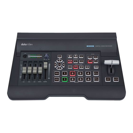
- Page 1 HD 4-CHANNEL DIGITAL VIDEO SWITCHER SE-650 Instruction Manual...
-
Page 2: Table Of Contents
Table of Contents FCC COMPLIANCE STATEMENT ......................5 WARNINGS AND PRECAUTIONS ......................5 WARRANTY ............................6 ..........................6 TANDARD ARRANTY ..........................6 HREE ARRANTY DISPOSAL ............................7 CHAPTER 1 INTRODUCTION ......................8 ............................8 EATURES ..........................9 YSTEM IAGRAM CHAPTER 2 CONNECTIONS AND CONTROLS ................... 10 .......................... - Page 3 -P K ..........................27 EYER 4.4.1 P-In-P Source .......................... 27 4.4.2 Keyer ............................28 4.4.3 Keyer Control ......................... 28 4.4.4 CK Setup ..........................28 4.4.5 Mask ............................28 ............................29 4.5.1 Logo Image ..........................29 4.5.2 Logo Control ........................... 29 4.5.3 Logo Source (Logo Src) ......................
- Page 4 SERVICE AND SUPPORT ........................80 Disclaimer of Product & Services The information offered in this instruction manual is intended as a guide only. At all times, Datavideo Technologies will try to give correct, complete and suitable information. However, Datavideo Technologies cannot exclude that some information in this manual, from time to time, may not be correct or may be incomplete.
-
Page 5: Fcc Compliance Statement
7. This product should only be operated from the type of power source indicated on the marking label of the AC adapter. If you are not sure of the type of power available, consult your Datavideo dealer or your local power company. -
Page 6: Warranty
• The product warranty period begins on the purchase date. If the purchase date is unknown, the product warranty period begins on the thirtieth day after shipment from a Datavideo office. • All non-Datavideo manufactured products (product without Datavideo logo) have only one year warranty from the date of purchase. -
Page 7: Disposal
Disposal For EU Customers only - WEEE Marking This symbol on the product or on its packaging indicates that this product must not be disposed of with your other household waste. Instead, it is your responsibility to dispose of your waste equipment by handing it over to a designated collection point for the recycling of waste electrical and electronic equipment. -
Page 8: Chapter 1 Introduction
It offers two HD SDI and two HDMI inputs. Output options include one user assignable HD SDI, two HDMI outputs. The SE-650 also features an audio mixer with microphone and unbalance RCA audio inputs; more features include Chroma Keyer, Luma Keyer, PIP, Wipe Generator, Still stores and Tally. -
Page 9: System Diagram
1.2 System Diagram... -
Page 10: Chapter 2 Connections And Controls
The SE-650 provides two HD-SDI video input channels for connecting HD-SDI video sources. HD-SDI Video Output 1 The SE-650 provides an HD-SDI video output channel which can be connected to an HD-SDI video display. HDMI Video Output 1-2 The SE-650 provides two HDMI video output channels which can be connected to any HDMI video monitors. - Page 11 Datavideo peripheral devices such as ITC-100, ITC-200, AM-100 or other monitor models, allowing the peripheral device to communicate with the SE-650 or send tally signal to be displayed on the monitor. MIC IN – CH1/CH2 Two Channels of unbalanced MIC input.
-
Page 12: Front Panel
Power Switch Power switch ON/OFF DC IN DC in socket connects the supplied 12V / 19W PSU. The connection can be secured by screwing the outer fastening ring of the DC In plug to the socket. 2.2 Front Panel Volume Control Switcher Transition PIP/Keyer... -
Page 13: Transition Effects
The white represents the current Program image and the black represents the WIPE-IN image. There are a total of 2 WIPE presets offered on the SE-650; the WIPE buttons allow the user to make a selection directly from the control panel for the first 2 and remaining 30 WIPE effects are selectable from the menu (Start). - Page 14 Wipe transition effect selection, border and position can be configured in the OSD menu (Start). Note: When WIPE and MIX buttons are enabled at the same time, the SE-650 enters the Clip Transition mode. PIP/Keyer PIP Enable/Disable buttons Picture in Picture puts the selected Sub Video Source in a window on the Main Program view, with control over window size and placement.
- Page 15 PIP PVW: Shows the configured PIP on PVW and multiview outputs. Holding down this button also allows selection of the PIP source from the Preview Source row. The selected source button will flash. Note: You are also allowed to apply the chromakey effect to the PIP window.
-
Page 16: Volume Control
Program / Preview Outputs Program Source Row Pressing the number buttons along the PROGRAM row selects a video source for the PGM view. BKG button: Pressing the BKG button will switch the background to the Matte background or color bars. Still button: Pressing the STILL button will switch the Main Program view to a still picture, which can be selected in the OSD menu. - Page 17 Headphone Jack Headphones jack accepts a stereo mini jack plug for stereo headphones. The headphone volume is controlled by the Headphone volume control knob. Audio Meters LED style meters, which show the signal strength at the Main Program Audio Output. The signal measured is determined by the level set with the Master slider.
-
Page 18: Chapter 3 Network Setup
Chapter 3 Network Setup The Ethernet port on the back panel of the SE-650 allows the user to import Still/Clip image or User memory using the Switcher Image Import/Export software discussed in Chapter 5. This chapter discusses direct connection between the SE-650 and your Windows computer as well as the remote setup in detail. -
Page 19: Installing The Switcher Image Import/Export Software To A Windows Computer
Installing the Switcher Image Import/Export software to a Windows Computer The SE-650 can be connected to a simple IP network and accessed using Windows-based software. If you have not already set up the SE-650 with a computer then please follow the instructions in the previous section. -
Page 20: Router Based Dhcp Setup
The computer software can also access the SE-650 over an existing TCP/IP LAN type network. In order to initially set up the SE-650, you may need the assistance of your local I.T. specialist to help with the network settings. To help guide you, we have included a simplified network setup example below, further advice may be available through your dealer locally or your Datavideo regional office. -
Page 21: Setting The Target Ip Address With The Switcher Image Import/Export Software
13. The computer, because it is set for DHCP, will already have an IP address automatically assigned to it in this list. 14. The SE-650 will also be listed with its default IP address of 192.168.1.101 if it is not changed. 15. Click save / apply then reboot the router again. - Page 22 Gateway: 192.168.1.1 DHCP Setup - If the IP set up method is changed to DHCP then each time the SE-650 is started, it may be given a different IP address by the network. Only use this method if you know how to find the SE- 650 on the internal IP network.
-
Page 23: Chapter 4 Osd Menu
4.1.2 Type The SE-650 provides three major types of transition effect, which are MIX, WIPE and Clip. Please note in addition to selecting the transition effect on the OSD menu, you are also allowed to press the MIX button, WIPE button or press MIX and WIPE buttons at the same time to enable the respective transition effects. -
Page 24: Position
Zero value positions the wipe center at the screen center. 4.1.6 Matte The user can configure the Matte by adjusting Luma, Saturation and Hue in this sub-option. 4.2 Keyer Keyer of the SE-650 provides the user with the capability of image keying. Advanced mode options Keyer Keyer... -
Page 25: Key Source
Gain adjusts the light/white areas of the key image. Opac adjusts the transparency of the overall foreground key image. 4.2.3 Key Source This sub-option allows the user to assign the key source; various options are listed below: • Bars • Matte – Set in Start/Matte •... -
Page 26: Mask
K Bgnd (Key Background): Key Background adjusts the performance of the chroma key in dark or black areas. Apply more Key Background if the dark areas are becoming too transparent. Hi-Light: Hi-light boosts the foreground key in high luminance area. Lo-Light: Lo-light boosts the foreground key in low luminance area. -
Page 27: Border
Horizontal Position (X) Positive value moves the PIP window to the right. Negative value moves the PIP window to the left. Zero value positions the PIP window at the screen center. Vertical Position (Y) Positive value moves the PIP window up. Negative value moves the PIP window down. -
Page 28: Keyer
• Freeze • Still 1 • Still 2 • Input 4 • Input 3 • Input 2 • Input 1 • Black Priority sets the key image to either the top layer or bottom layer. 4.4.2 Keyer The “Keyer” option defines the keyer mode, which is either Chroma or Full mode. Chroma Mode: Chromakeying on PIP screen Full Mode: Enabling of full PIP screen mode with the PIP window covering the entire screen. -
Page 29: Logo
Note: We do not recommend using the two-source logo (Split) as it requires two physical connection ports. An example of Linear Keyer in Self mode: HDMI input port is connected to a Windows notebook running Datavideo’s CG-200 software. 4.5.2 Logo Control Logo Control adjusts lift, gain and opacity of the logo image. -
Page 30: Fill Source
4.5.6 Logo Insertion The SE-650 allows the user to place a logo on the video by enabling the logo feature. First of all, create a 1920x1080 (16:9) logo against a black or white background on a laptop. Once the logo is created, please follow the steps outlined as follows to insert the logo layer. -
Page 31: Stills
Note: To make sure the saved logo will be loaded to Still 2 on the next machine boot, before rebooting your machine, please first go to Load Still and load the logo saved at Step 5 to Still 2. 6. Browse to the Logo option and select Still 2 as the logo source (Logo Src). Logo Fill should be assigned to Still 2 as well. -
Page 32: Save Still
4.6.2 Save Still “Save Still” allows the user to save the still image to a specific memory location. The user should determine the source of the still image first. The available sources are listed below: • Still 1 • Still 2 •... - Page 33 • First connect the SE-650 to a Windows computer using an RJ-45 Ethernet cable. • Since the SE-650 has a default IP address of 192.168.1.101 so the computer should be given the IP settings that match the same IP range as the switcher.
- Page 34 5. When you see the safety warning requesting for permission to allow an unknown publisher to make changes to the PC, please click “Yes” to continue. 6. Wait for the installation to finish.
- Page 35 7. After the setup is complete, you will see the following window; click “Finish” to launch SwitcherImageImEx immediately. 8. After the setup is finished, a shortcut will be created in Start Menu > Programs > datavideo > tools > SwitcherImageImEx 9.
- Page 36 2. If the available device is scanned and found, the connection will be automatically established. After the connection is successfully established, the Connect Status will show “Connected” (will display Not Connected if disconnected). 3. After clicking the Setup button, the network information will be displayed in the blue area (identical to the SE-1200 MU user control interface).
- Page 37 4. After clicking Import-Export, you will be able to see four options which are Import Still, Import User, Import Clip and Export. 5. When in Import Still, click a Still number first and enter a location for storing the still. Then click Import Still again, the interface for selecting picture files will appear.
-
Page 38: Loading Still Images
SwitcherImageImEx from your computer. 4.6.6 Loading still images The SE-650 allows the user to load still images saved on the machine to the Multiview screen. Please follow the steps outlined below to load the still picture. 1. Press the MENU button to open the OSD menu on the Multiview display. -
Page 39: User Mems
Once “Load” is pressed, the selected clip will be loaded into the Still 2 window and replace the previously displayed video or image. Note: The SE-650 comes with pre-loaded clip files. The SE-650 also allows the user to import customized clip files. It is recommended to use 32-bit with Alpha png format. -
Page 40: Loading The Existing Clip For Stinger Transition Effect
4.7.5 Importing the Clip for Stinger Transition Effect from the PC On the SE-650, you will be able to add a clip between sources. Besides using the existing clips on the machine, you are also allowed to import your own clip (a series of bmp/png/jpg/pic files) to the SE- 650 from the PC using the Switcher Image Import/Export utility, which can be downloaded from the SE-650 product page. - Page 41 Select Import-Export from the yellow menu options. The clip number allows you to select a location where you can save the clip. To import a clip from the computer into the SE-650, select Import Clip.
-
Page 42: How To Create The Png Sequence For Stinger Transition Effect
After the clip file is created, there are two ways to convert the file to the PNG sequence format readable by the SE-650 switcher in Adobe After Effects. In this section, we will show you how you can create the PNG sequence for the Stinger transition effect. - Page 43 2. The Render Queue will be displayed in the bottom pane. 3. Click Output Module and on the Main Options window, click the Format dropdown list and select PNG Sequence.
- Page 44 4. Click the Channels dropdown list and select the “RGB + Alpha” option.
- Page 45 5. Click “Output To” and then change the location where your files are rendered. Click Render after that. The next section outlines the file conversion procedure using the Media Encoder CC. Media Encoder CC 1. Click Composition → Add to Media Encoder Queue (or alternatively, you can also click File Export ...
- Page 46 3. Click the Format dropdown list and then select PNG. 4. Click the Preset dropdown list and select “PNG Sequence with Alpha.”...
- Page 47 5. Make sure “Export As Sequence” and “Include Alpha Channel” are checked and then click OK. 6. Select “Output File” to choose the render files destination. Click the green button to render. 7. Once completed, the status will display “Done.” After the sequential files are created and ready, see section 5.4.2 to import the Clip file to the switcher.
-
Page 48: Important Things To Note While Creating Stinger Transition Effects
The length of a good stinger transition animation should be approximately 0.5 to 2 seconds. 2. The SE-650 allows a maximum of 200 image files in an animation sequence The number of image files will determine the length of stinger transition time. -
Page 49: Inputs
4.8 Inputs This feature allows the user to configure the color of the Inputs 1-4. In addition, the user can shuffle the contents of Inputs 1-4 and Stills. Advanced mode options Inputs Input 1 Black 0 White 100 Chrom Input 2 Black 0 White 100 Chrom... -
Page 50: Outputs
In this sub-option, you can turn ON/OFF the embedded audio component at the SDI-out and HDMI- out. Mode (Off/Analog): The SE-650 can only accept external audio using the analogue RCA inputs on the rear panel. By changing the Mode sub-option from Analogue to OFF will mute the incoming RCA audio. -
Page 51: Tally Mode
59.94/60 Hz, the audio follows SMPTE standard. Src: If “Follow” is selected, the audio will enter Audio follow Video mode, i.e. playback of the audio of the output video. If “Src” is selected, the SE-650 will play all enabled audio sources. 4.9.3 Tally Mode Tally output port generally sends two tally signals to each channel. -
Page 52: Standard
4.10.1 Standard This option allows the user to choose the appropriate output resolution such as 1080i/50. Once done, simply select “Save” to confirm the selected output resolution. The available resolutions are 1080i/50/59.94/60, 720p/60/59.94/50. 4.10.2 Menu Mode The user is allowed to switch between full and simplified menu versions. Select “Advanced” for full menu display or “Basic”... -
Page 53: Chapter 5 Applications
5.2 Logo Insertion The SE-650 allows the user to place a logo on the video by enabling the logo feature. First of all, create a 1920x1080 (16:9) logo against a black or white background on a laptop. Once the logo is created, please follow the steps outlined as follows to insert the logo layer. -
Page 54: Still Images
• First connect the SE-650 to a Windows computer using an RJ-45 Ethernet cable. • Since the SE-650 has a default IP address of 192.168.1.101 so the computer should be given the IP settings that match the same IP range as the switcher. - Page 55 Installation 1. Download SwitcherImageImEx_vx.x.x.msi from the product page and save it on the local disk. 2. Click the installation file icon to start the Setup Wizard. 3. Click “Next” 4. Click “Install”...
- Page 56 5. When you see the safety warning requesting for permission to allow an unknown publisher to make changes to the PC, please click “Yes” to continue. 6. Wait for the installation to finish. 7. After the setup is complete, you will see the following window; click “Finish” to launch SwitcherImageImEx immediately.
- Page 57 8. After the setup is finished, a shortcut will be created in Start Menu > Programs > datavideo > tools > SwitcherImageImEx 9. Click SwitcherImageImEx to open the program. How to use 1. When the program is executed for the first time, it will automatically scan the network and if multiple network interface cards are found, please select the card that is on the same network as the device.
- Page 58 2. If the available device is scanned and found, the connection will be automatically established. After the connection is successfully established, the Connect Status will show “Connected” (will display Not Connected if disconnected). 3. After clicking the Setup button, the network information will be displayed in the blue area (identical to the SE-1200 MU user control interface).
- Page 59 4. After clicking Import-Export, you will be able to see four options which are Import Still, Import User, Import Clip and Export. 5. When in Import Still, click a Still number first and enter a location for storing the still. Then click Import Still again, the interface for selecting picture files will appear.
-
Page 60: Loading Still Images
SwitcherImageImEx from your computer. 5.3.2 Loading still images The SE-650 allows the user to load still images saved on the machine to the Multiview screen. Please follow the steps outlined below to load the still picture. 1. Press the MENU button to open the OSD menu on the Multiview display. -
Page 61: Stinger Transition Effect
5.4.1 Loading the existing Clip for Stinger Transition Effect The SE-650 allows you to generate the stinger transition effect. To do this, the user should first load the clip saved on the machine to the Still 2 window of the Multiview screen first. Please follow the steps outlined below to load the clip. -
Page 62: Importing The Clip For Stinger Transition Effect From The Pc
5.4.2 Importing the Clip for Stinger Transition Effect from the PC On the SE-650, you will be able to add a clip between sources. Besides using the existing clips on the machine, you are also allowed to import your own clip (a series of bmp/png/jpg/pic files) to the SE- 650 from the PC using the Switcher Image Import/Export utility, which can be downloaded from the SE-650 product page. - Page 63 To import a clip from the computer into the SE-650, select Import Clip. Note: The Switcher Image Import/Export utility does the conversion from bmp/png/jpg to the .pic file format. All you need is to give the utility a starting file location and it will give the utility an idea where to start linking all images up into a sequential animation file.
-
Page 64: How To Create The Png Sequence For Stinger Transition Effect
After the clip file is created, there are two ways to convert the file to the PNG sequence format readable by the SE-650 switcher in Adobe After Effects. In this section, we will show you how you can create the PNG sequence for the Stinger transition effect. - Page 65 3. Click Output Module and on the Main Options window, click the Format dropdown list and select PNG Sequence. 4. Click the Channels dropdown list and select the “RGB + Alpha” option.
- Page 66 5. Click “Output To” and then change the location where your files are rendered. Click Render after that. The next section outlines the file conversion procedure using the Media Encoder CC. Media Encoder CC 1. Click Composition → Add to Media Encoder Queue (or alternatively, you can also click File Export ...
- Page 67 3. Click the Format dropdown list and then select PNG. 4. Click the Preset dropdown list and select “PNG Sequence with Alpha.”...
- Page 68 5. Make sure “Export As Sequence” and “Include Alpha Channel” are checked and then click OK. 6. Select “Output File” to choose the render files destination. Click the green button to render. 7. Once completed, the status will display “Done.” After the sequential files are created and ready, see section 5.4.2 to import the Clip file to the switcher.
-
Page 69: Important Things To Note While Creating Stinger Transition Effects
The length of a good stinger transition animation should be approximately 0.5 to 2 seconds. 2. The SE-650 allows a maximum of 200 image files in an animation sequence The number of image files will determine the length of stinger transition time. -
Page 70: User Memory
5.5 User Memory The user memory allows the user to save the current switcher settings to different presets. You will be able to import/export these memory presets from/to the PC. In this section, we will show you how you can import and export these user memory presets step by step. 5.5.1 Export/Import User Memory Preset to/from the PC 1. - Page 71 3. As soon as “Import User” is clicked, the PC hard disk browser window will open; select a .mem file to import a user settings file. 4. To export, simply click “Export” and the following window will open; select a preset number to export the user settings to the PC in .mem file.
-
Page 72: Loading User Memory Preset
5.5.2 Loading User Memory Preset The SE-650 allows the user to load user memory presets saved on the machine to the Multiview screen. Please follow the steps outlined below to load the user memory preset. 1. Press the MENU button to open the OSD menu on the Multiview display. -
Page 73: Chapter 6 Appendices
Appendix 1 Tally Outputs The SE-650 has a D-sub 15 pin female tally output port. These connections provide bi-colour tally information to a number of other Datavideo products, such as the ITC-100 eight channel talkback system and the TLM range of LCD Monitors. The ports are open collector ports and as such do not provide power to tally light circuits. -
Page 74: Appendix 2 Firmware Upgrade
Firmware Upgrade Datavideo usually releases new firmware containing new features or reported bug fixes from time to time. Customers can either download the SE-650 firmware as they wish or contact their local dealer or reseller for assistance. This section outlines the firmware upgrade process which should take approximately 10 minutes to complete. -
Page 75: Appendix 3 Frequently-Asked Questions
Appendix 3 Frequently-Asked Questions This section describes problems that you may encounter while using SE-650. If you have any questions, please refer to related sections and follow all suggested solutions. If problem still exists, please contact your distributor or the service center. -
Page 76: Appendix 4 Dimensions
Appendix 4 Dimensions All measurements in millimeters (mm) -
Page 77: Appendix 5 Specifications
Appendix 5 Specifications Interfaces 4 sets of input Video Inputs 2 x HDMI 2 x HD-SDI 2 x HDMI (HDMI 1 is user assignable / HDMI 2 is Multiview) Video Outputs 1 x HD-SDI (User assignable) 1 x Stereo RCA (L/R) Audio Inputs 2 x Mono Microphone De-embedded Digital Audio (2 CH) - Page 78 NOTE...
- Page 79 NOTE...
-
Page 80: Service And Support
Service & Support It is our goal to make owning and using Datavideo products a satisfying experience. Our support staff is available to assist you to set up and operate your system. Contact your local office for specific support requests. Plus, DATAVIDEO WORLDWIDE OFFICES please visit www.datavideo.com to access our FAQ section.
Need help?
Do you have a question about the SE-650 and is the answer not in the manual?
Questions and answers