Table of Contents
Advertisement
Advertisement
Table of Contents

Related Manuals for Daikin BRC1C71


Summary of Contents for Daikin BRC1C71
-
Page 2: Table Of Contents
EDUS39-605A-C Controls 1. Control Systems..................2 2. Control Devices...................3 2.1 BRC1C71 Wired Remote Controller............. 3 2.2 BRC4C / 7C / 7E Wireless Remote Controller / Receiver ......11 2.3 BRC2A71 Simplified Remote Controller............. 13 2.4 DCS302C71 Central Remote Controller ............ 16 2.5 DCS301C71 Unified ON/OFF Controller............ -
Page 3: Control Systems
FXNQ~MVJU FXHQ~MVJU FXDQ~MVJU Item Type Wireless BRC7C812 BRC4C82 BRC7E818 — BRC7E83 BRC4C82 Remote controller Wired BRC1C71 Wired 7-day programmable remote controller BRC1D71 Remote sensor KRCS01-1 Installation box for adaptor PCB — KRP1C93 KRP1B101 KRP1B98 Central remote controller DCS302C71 5-1 Electrical box... -
Page 4: Control Devices
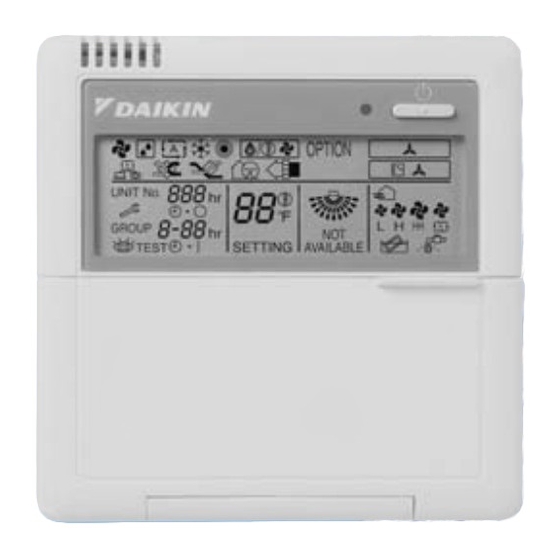
EDUS39-605 Control Devices 2. Control Devices BRC1C71 Wired Remote Controller The optional Remote Controller for indoor units provides versatile system control. Remote controller wiring for a simplified BRC2A71 Remote Controller is the same as that of the standard BRC1C72 Remote Controller. Because the functions of the simplified remote controller are limited, we recommend using in combination with a central remote controller. -
Page 5: Group Control
Control Devices EDUS39-605 2.1.3 Two Remote Controllers 1 indoor unit is controlled by 2 remote controllers from 2 separate locations This is a convenient system for operating an office indoor unit from the reception area, or an indoor unit from a local or remote location. - Page 6 EDUS39-605 Control Devices 2.1.5 Remote Controller and Changeover Switch: Name and Function of Each Switch and Display 1. ON/OFF button Press tto start; press again to stop system. 2. Operation lamp red The lamp lights during operation. 3. Display indicates changeover under control It is impossible to changeover heat/cool with the remote controller when this icon is displayed.
- Page 7 Control Devices EDUS39-605 Refer to the indoor unit manual. 19.Fan speed control button Select the fan speed. 20.Operation mode selector button Select the operation mode. o 21.Air flow direction adjust button Refer to the chapter Operation procedure - Adjusting the air flow direction. 22.Fan only/air conditioning selector switch Set the switch to for fan only operation or to...
- Page 8 EDUS39-605 Control Devices 2.1.6 Installation Controls...
- Page 9 Control Devices EDUS39-605 18 – 2AWG Controls...
- Page 10 EDUS39-605 Control Devices 2.1.7 Field Setting Wired Remote Controller BRC1C71 If optional accessories are mounted on the indoor unit, its settings may have to be changed. Refer to the instruction manual for each setting. Procedure 1. When in the normal mode, press the button for a minimum of four seconds, and the FIELD SET MODE is entered.
- Page 11 3. Mode not displayed if the indoor unit is not equipped with that function. 4. When returning to the normal mode, [ ] may be displayed in the LCD in order for the remote controller to initialize itself. 2.1.8 Dimensions BRC1C71 18-2 AWG 3D045753 Controls...
-
Page 12: Brc4C / 7C / 7E Wireless Remote Controller / Receiver
EDUS39-605 Control Devices BRC4C / 7C / 7E Wireless Remote Controller / Receiver BRC7C812 2-7/16 11/16 C:3D005912D BRC4C82 1/32 2-3/4 11/16 1-3/8 2-7/16 11/16 2-3/16×3/8 1-15/16 C:3D007898A Controls... - Page 13 Control Devices EDUS39-605 BRC7E83 3D049336 BRC7E818 11/16 2-7/16 C:3D034905B Controls...
-
Page 14: Brc2A71 Simplified Remote Controller
EDUS39-605 Control Devices BRC2A71 Simplified Remote Controller 2.3.1 Name and Function BRC2A71 REMOTE CONTROLLER: NAME AND FUNCTION OF EACH SWITCH AND DISPLAY DISPLAY “ ” (UNDER CENTRALIZED ON/OFF BUTTON CONTROL) When this display shows, the system is UNDER Press the button and the system will start. Press the CENTRALIZED CONTROL. -
Page 15: Initial Setting
Control Devices EDUS39-605 2.3.2 Installation 1. Remove the upper part of remote controller. Insert a minus screwdriver into the slot between the upper and the lower part of remote controller. NOTE 1. Do not directly touch the PC board with your hand. 2. - Page 16 EDUS39-605 Control Devices NOTES " " 2If controlling with one remote controller, be sure to set it to MAIN. 2Set the remote controller before turning power supply on. " " is displayed for about one minute when the power supply is turned on, and the remote controller cannot be operated in some cases.
-
Page 17: Dcs302C71 Central Remote Controller
Control Devices EDUS39-605 DCS302C71 Central Remote Controller You can connect up to 64 groups of indoor units (maximum 128 units) and operate or monitor ON/OFF, temperature settings, and so forth, by individual zone or together. Up to 2 units are connectable within 1 system and up to 4 units in case of the double central control mode. - Page 18 EDUS39-605 Control Devices System Configuration for Group / Zone Control Group control Group control configuration allows all indoor units to be connected by the same remote controller connected to terminal P1 and P2, and all the units in group have the same setting and the same operation. The group of indoor units is controlled by the master indoor unit’s remote controller.
- Page 19 Control Devices EDUS39-605 System Configuration (Control by 2 central remote controllers) Up to 128 indoor units can be connected in one system. 2 or 4 central remote controllers are required. It is possible to control the same unit from 2 locations. Up to 16 unified ON/OFF controllers can be connected using 8 controllers covering 2 locations.
- Page 20 EDUS39-605 Control Devices 2.4.2 Specifications / Dimensions Specifications DCS302C71 Power supply voltage / frequency AC100~240V ±10% 50/60Hz Power consumption Max. 8W Setting data backup Non-volatile memory preserves data semi-permanently Effects of instantaneous power failure No effect for 20 mili-sec. or less Forced OFF input No-voltage normal open contact Operation on the local side cannot be carried out...
- Page 21 Control Devices EDUS39-605 2.4.3 Names and Functions of Operating Part Display part DISPLAY (OPERATION MODE) Displays operating state. DISPLAY(VENTILATION DISPLAY (OPERATION OPERATION LAMP (RED) UNIFIED OPERATION UNIFIED STOP BUTTON CLEANING DISPLAY) MODE) BUTTON Lit white any of the indoor Press to stop all indoor This is displayed when a Ventiair Displays operating state.
- Page 22 EDUS39-605 Control Devices 2.4.4 Description of Functions Individual Screen, All Screen, Zone Screen This controller can perform operations in the following screens: INDIVIDUAL SCREEN for performing group operations. ALL SCREEN for performing operations for all units at once. ZONE SCREEN for performing zone operations. Basic functions Function Descriptions of outline...
- Page 23 Control Devices EDUS39-605 Cool/Heat changeover and settings Function Descriptions of outline Possible control The operation mode of the outdoor unit can be changed by the local remote controller or by the central remote controller. For test operation, change setting of cool/heat selector switch of the outdoor unit.
- Page 24 EDUS39-605 Control Devices Use the following procedure to set operation mode: Continue to push Operation switch Push Operation switch of the remote for about 4 seconds. controller, which you want to set the sign blinks on all the indoor units selection eligibility.
- Page 25 Control Devices EDUS39-605 Control with Two Central Remote Controllers The central remote control equipment is the newly designed C type that allows 2 central remote controllers to be connected as shown in the following example: Note: If a timer number is registered by the sub central remote controller, the timer mode for the local remote controller (mode no.
- Page 26 EDUS39-605 Control Devices Sequential Start Operation command from central control equipment Each unit operates in sequence. For example, if you set simultaneous operation by the central remote controller for groups 1-00 ~ 4-15, and 5-00 ~ 8-15, two outdoor units start simultaneously. Registering Zone It is possible to set multiple groups as one zone and control each zone separately.
- Page 27 Control Devices EDUS39-605 Batch deletion of zone registration Pressing the ALL for at least four seconds while pressing the FILTER SIGN RESET button when ZONE SET is displayed deletes all zone registrations. Zone setting To set all zones for uniform operation, the central remote controller should display Zone 0 with the following modes selected: Operation mode Control mode...
- Page 28 EDUS39-605 Control Devices Changing the Fan Direction and Fan Strength Changing the fan direction and strength is accessed from the following screen: . INDIVIDUALLY Registration Press the ALL/INDIVIDUAL button to enter the individual screen. The unit opens the individual screen automatically if nothing is done for one minute. Using the arrow keys, move the to select the units to fan direction adjustment or fan strength...
- Page 29 Control Devices EDUS39-605 Once the desired timer number is displayed, press the SET button. Press the SET button within 10 seconds after the timer number is displayed. The display will return to how it was after 10 seconds. The display for timer number 1 will stop blinking and then timer number 2 will start blinking. Select the desired timer number by pressing the TIMER NO.
- Page 30 EDUS39-605 Control Devices 2.4.5 Wiring Instructions Wiring instructions For control wiring of DIII-NET, you can select from the following 3 types of wiring methods: 1. Series method: Wiring is connected by a single line from the central controller. 2. Bus method: Up to 16 branches are possible.
- Page 31 Control Devices EDUS39-605 2.4.6 Instructions for Initial Setting Group No. Setting for Central Control Equipment Group No. should be set for each group by the remote controller for indoor unit when you operate the system with central remote controller and unified ON/OFF controller. For the same control group, set only one of the units. Remote controller for indoor unit Simplified remote controller 1.
- Page 32 EDUS39-605 Control Devices Cautions Even in the systems without remote control, connect the remote controller once to set the Group Number for addressing the central control equipment and after it is set, remove the remote controller. When you set the group No., be sure to supply power to the central remote controller, the unified ON/OFF controller, and the indoor unit.
- Page 33 Control Devices EDUS39-605 2.4.7 Selection of Control Mode No. Select whether to accept or reject operations by local remote controller such as Turning on/off, temperature adjustment and operation mode setting respectively, and decide the control mode No. shown in the right side of the following table: Example: Operation from local remote Operation from local remote...
- Page 34 EDUS39-605 Control Devices Timing Chart for Scheduled Operation and each Control Mode No. (VRV system) are as follows: 1. Remote controller rejection: Code No. 0, 1, 10, 11 2. Remote controller off only accepted: Code No. 2, 3, 12, 13 3.
- Page 35 Control Devices EDUS39-605 5. Remote controller permission timer: Code No. 8, 9, 18, 19 It switches to the cord of "Remote Controller Permission Timer" Remote Controller Permission Timer Last command Operation Cord Schedule Schedule priority ON Time OFF Time ON Time OFF Time Schedule Timer Operation by Central...
- Page 36 EDUS39-605 Control Devices 2.4.8 Setting of Central Remote Controller: Be sure to set 1 ~ 3 before electrical power is supplied. 1. Connector for setting MAIN for control is provided when shipped from factory When only one central remote controller is used, never remove the connector for setting MAIN for control. When plural central remote controllers are used or a central remote controller is used with other central controllers, the setting should be made according to the following table: Pattern of central control equipment connection.
- Page 37 Control Devices EDUS39-605 4. Forced reset switch When changing the setting of the connector for the main controller, you can reset simply by setting it to the reset side once and returning to the normal side, without turning the power OFF. For normal operation, set the switch to the normal OFF side.
- Page 38 EDUS39-605 Control Devices Heating Mode Heating 72°F Fan Mode Fan Operation Examples of functionality with Refreshed Operation: If the setting is changed by DCS302C71, the unit operates by this setting from the next operation. if originally set to 79°F cooling by DCS302C71, the next operation also operates at 79°F for cooling mode. Even if it has changed into heating operation, or fan-only operation with wired or wireless remote control, it operates at 79°F in cooling mode.
- Page 39 Control Devices EDUS39-605 Setting Contents and Setting No. No. of setting switch Mode No. Setting contents Setting of sequential operation function – Setting of refresh function – Setting of restriction items from sub-central remote Disabled Enabled – controller while in double central control function Forced OFF all Forced OFF only Forced thermostat...
- Page 40 EDUS39-605 Control Devices Installation (1) Open the upper part of remote controller. Insert a – screwdriver (2 locations) into the recess between the upper part and the lower part of remote controller and twist the screwdriver lightly. – screwdriver (2 locations) PC board is attached with both the upper and lower part of remote controller.
-
Page 41: Dcs301C71 Unified On/Off Controller
Control Devices EDUS39-605 DCS301C71 Unified ON/OFF Controller Turns up to 16 groups of indoor units (max. 128 units) on/off (operation/stop) by individual group or simultaneously and enables view of operation/malfunction at the same time. For a maximum of 16 groups of indoor units (max. 128 units), unified operation/stop or individual operation/stop can be performed with this optional accessory. - Page 42 EDUS39-605 Control Devices The groups of indoor units are as follows: 1. One indoor unit without remote controller 2. One indoor unit controlled by one or two remote controllers 3. A maximum of 16 indoor units controlled in groups by one or two remote controllers 2.5.2 Electric Wiring General Instructions All wiring, components, and materials procured on the site must comply with the applicable local and national codes.
- Page 43 Control Devices EDUS39-605 Examples of Wiring for Transmission 1. Series Wiring 2. Bus Type Wiring: Can be branched up to 16 branches Example of 3 branches 3. Star Type Wiring: Can be branched up to 16 branches Example of 3 branches Note: 1.
- Page 44 EDUS39-605 Control Devices Wiring to the Indoor Unit and Outdoor Unit WARNING: Do not connect the power supply wiring to the control terminal strip. If connected by mistake, it may damage or burn electrical parts of optional controllers for centralized control and indoor unit and can be dangerous. Be sure to check wirings before turning the power ON.
- Page 45 Control Devices EDUS39-605 2.5.4 Installation 1. Open the upper part of remote controller. Insert a minus screwdriver (2 locations) into the recess between the upper part and the lower part of remote controller and twist the screwdriver lightly. PC board is attached with both the upper and lower part of remote controller. Do not damage the board with the screwdriver.
- Page 46 EDUS39-605 Control Devices 2. Switch for Setting Each Address (DS1) The following switches are used to set group control address: Group Numbers 1-00 through 1-15 are in the same control group when the unit is shipped from the factory. After setting, attach the number seal applicable to respective control range of the attached switch display sticker, as shown in the diagram below.
- Page 47 Control Devices EDUS39-605 5. Control Mode Selector (DS2) The following four patterns of control mode can be set: Control Mode Individual Centralized Timer Operation Possible by ON/OFF Control Impossible Remote Controller by Remote Controller Content Operation/stop is After operation by unified When used in conjunction Operation/stop is controlled controlled by both unified...
-
Page 48: Confirming Operation
EDUS39-605 Control Devices 2.5.6 Setting Group No. for Centralized Control Set the group number of each group of the indoor unit from the remote controller. In no remote controller, also connect the remote controller and set the group number and remove the remote controller. 1. -
Page 49: Dst301Ba61 Schedule Timer
Control Devices EDUS39-605 DST301BA61 Schedule Timer Enables you to connect and control weekly schedules for up to 128 indoor units. Simultaneous control of up to 128 indoor units is managed by a week schedule. The start and stop time for twice a day can be set for the week in increments of 1 minute. - Page 50 EDUS39-605 Control Devices 2.6.2 Names and Functions DST301BA61 DST301BA61 Fig. 1 DST301BA61 Fig. 2 3P124623-5C Controls...
- Page 51 Control Devices EDUS39-605 BUTTON FOR SELECTING DAYS OF A WEEK UNIFIED OPERATION BUTTON Press to perform the unified operation regardless of Press to select the day of the week. the programmed time. HOUR/MINUTE BUTTON UNIFIED STOP BUTTON Press to adjust the present time and the programmed Press to perform the unified stop regardless of the time.
- Page 52 EDUS39-605 Control Devices 2.6.3 Dimension Schedule Timer DST301BA61 Unit (in) 2 3/16 × 1/4 1 3/4 4 3/4 1 7/16 3 1/2 C:3D049544 2.6.4 Installation and Initial Setting 1. Remove the upper part of the remote controller. Insert a minus screwdriver (2 locations) into the recess between the upper part and the lower part of the remote controller and turn the screwdriver lightly.
- Page 53 Control Devices EDUS39-605 Attach the lower part to the electrical box (part to be procured in the field) with the provided installation screws. Select a flat face as an installation place. Do not tighten the installation screws excessively or it might damage the lower part of the remote controller.
- Page 54 EDUS39-605 Control Devices 4. Forced Reset Switch (SS1) When changing the setting of the connector for individual use, the switch can be reset simply by setting it to the reset side once and returning to the normal side. This procedure enables to reset without turning off the power. Set the normal side at normal operation.
- Page 55 This schedule timer is provided with the malfunction-diagnosing function. The malfunction code flashes if there are any communication malfunctions between the optional controllers for centralized control. In addition, the operation lamp also flashes if there are any malfunctions with the indoor unit. Check the display and contact your DAIKIN dealer to report the trouble area indicated.
-
Page 56: Brc1D71 7-Day Programmable Controller
EDUS39-605 Control Devices BRC1D71 7-Day Programmable Controller New, advanced functions are as follows: Includes ventilation mode and airflow rate switching, the main functions of HRV series. 24-hour clock function with 1-hour backup for power failures. Programming function for each day of week. Scheduling for start/stop and temperature limits with 5 settings/ Programming can be enabled or disabled. -
Page 57: Features And Functions
Control Devices EDUS39-605 2.7.2 Features and Functions The BRC1D71 is a state-of-the-art remote controller that offers full control. BASIC REMOTE CONTROLLER FUNCTIONS ON/OFF Operation mode change-over Temperature adjustment Air volume adjustment Air flow direction adjustment CLOCK FUNCTIONS 24 hours real time clock Day of the week indicator SCHEDULE TIMER FUNCTIONS Maximum of 5 actions can be programmed for each day of the week... - Page 58 EDUS39-605 Control Devices 2.7.4 Name and Function of Switches and Icons (Refer to figure 1) ON/OFF BUTTON MAXIMUM SET TEMPERATURE Press the ON/OFF button to start or stop the system. The maximum set temperature indicates the maximum set temperature when in limit operation. OPERATION LAMP Lights during operation or blinks if a malfunction occurs.
- Page 59 Control Devices EDUS39-605 VENTILATION MODE BUTTON of the week. The ventilation mode button operates the ; refer to OPERATION CHANGE/ BUTTON manual for more details. This button is a multi-purpose button. Depending on the previous manipulations of the user, it can have following VENTILATION AMOUNT BUTTON functions: Sets the ventilation amount;...
- Page 60 EDUS39-605 Control Devices 2.7.5 Installation 3. Wire the indoor unit The kit includes the following parts: Remote controller Wood screws P2 P1 P2 P1 Wall plugs Machine screws indoor unit 1. Remove the upper part of remote controller lower part of the remote controller upper part of the remote controller wired from the rear wired from the top...
- Page 61 Control Devices EDUS39-605 If controlling one indoor unit or one group of 6. Field settings indoor units with two remote controllers If optional accessories are mounted on the indoor unit, the Change the MAIN/SUB changeover switch setting as indoor unit setting may have to be changed. Refer to the described below.
- Page 62 EDUS39-605 Control Devices Mode FIRST SECOND CODE NO. Note 2 CODE Note 1 Description of setting Approx. Approx. Ultra long 10.000 5.000 life filter hrs. hrs. Filter Contamination - Heavy/Light are settings Approx. Approx. for for spacing of display time to clean air filter: Long life —...
-
Page 63: Dcs601C71 Intelligent Touch Controller
Control Devices EDUS39-605 DCS601C71 intelligent Touch Controller 2.8.1 Features Central remote controller offering more advanced functionality and easier operation than the previous DSC302C71 controller. Up to 64 groups of indoor units may be connected to 1 unit of this controller. This controller aims to be a product positioned between the current central controlling device (central controller DCS302C71) and the controller D-BIPS for large scale buildings (in both the viewpoints of application area... -
Page 64: System Overview
EDUS39-605 Control Devices Handy Automated Control The intelligent Touch Controller offers the following automated controls: • Change Over Settings : automatically switches between cooling and heating according to the room temperature. • Temperature Limit Setting : prevents the temperature from rising too high or too low in unmanned rooms. •... - Page 65 Control Devices EDUS39-605 2.8.3 Options Connecting Unification adaptor allows using the contact for normal and abnormal operation signal and collective start/stop with a contact. For details, contact the vendor you purchased the product from. Monitoring from PC is possible by Web E-mail functions.
-
Page 66: Part Names And Functions
EDUS39-605 Control Devices 2.8.5 Part Names and Functions Front and Side View PCMCIA Card Slot Color LCD with Touch Panel Touch Pen Used when updating the Provides a display for monitoring Use the touch pen for operation. intelligent Touch Controller and operation. - Page 67 Control Devices EDUS39-605 2.8.6 Monitoring Screen Labels and Functions Display Mode Selection Contents of the List Currently Displayed Zone/Group Currently Displayed Select between Zone and Group. When Group List is displayed The name of the zone/group currently “Zone: Zone Name” selected is highlighted in blue flame.
- Page 68 EDUS39-605 Control Devices Icons Contents of the List Currently Displayed Zone/Group Currently Displayed Display Mode Selection When Group List is displayed The name of the zone/group currently Press the button ana display “Zone: Zone Name” selected is highlighted in blue frame. change between Zone and Group.
- Page 69 Control Devices EDUS39-605 Lists: Contents of the List Currently Displayed Zone/Group Currently Displayed Display Mode Selection The name of the zone/group Press the button and display When Group List is displayed currently selected is highlighted change between Zone and Group. “Zone: Zone Name”...
- Page 70 EDUS39-605 Control Devices 2.8.7 Electrical Wiring Connection Controls...
- Page 71 Control Devices EDUS39-605 Controls...
- Page 72 EDUS39-605 Control Devices Controls...
- Page 73 Control Devices EDUS39-605 1P167242A Controls...
- Page 74 EDUS39-605 Control Devices 2.8.8 DCS004A71 Web Software for the intelligent Touch Controller Functions and Outline This software enables you to operate and monitor air conditioners linked to the intelligent Touch Controller on your Windows PC, which is connected to the intelligent Touch Controller and the Ethernet communication (LAN). ∗...
-
Page 75: Adaptors
Adaptors EDUS39-605 3. Adaptors KRCS01-1 Remote Sensor The built-in temperature control thermistor of the indoor unit is mounted in the intake port of the main body. Some differences can occur between the temperature setting of the built-in thermistor and the actual indoor temperature. In such cases, remove the thermistor from the indoor unit and remount it near the living area so that the remote sensor can sense the temperature of the living area. -
Page 76: Dta104A 53/ 61/ 62 Required Outdoor Unit External Control Adaptor
EDUS39-605 Adaptors DTA104A 53/ 61/ 62 Required Outdoor Unit External Control Adaptor Must be installed on Indoor Units C:1PA63164D-1 Controls... - Page 77 Adaptors EDUS39-605 C:1PA63164D-2 Controls...
-
Page 78: Dta109A51 Diii Net Expander Adaptor
EDUS39-605 Adaptors DTA109A51 DIII NET Expander Adaptor Controls... - Page 79 Adaptors EDUS39-605 Controls...
- Page 80 EDUS39-605 Adaptors Controls...
-
Page 81: Krp1B71 / 72 / 73 Adaptor For Wiring
Adaptors EDUS39-605 KRP1B71 / 72 / 73 Adaptor for wiring Controls... - Page 82 EDUS39-605 Adaptors C:2P164806 Controls...
-
Page 83: Krp4A71 / 72 / 73 / 74 Wiring Adaptor For Electrical Appendices
Adaptors EDUS39-605 KRP4A71 / 72 / 73 / 74 Wiring Adaptor for Electrical Appendices Controls... - Page 84 EDUS39-605 Adaptors 1P161220 Controls...
- Page 85 Adaptors EDUS39-605 Controls...
- Page 86 EDUS39-605 Adaptors Controls...
- Page 87 Adaptors EDUS39-605 C:1P161221 Controls...
-
Page 88: Dcs302A72 Unification Adaptor For Computerized Control
EDUS39-605 Adaptors DCS302A72 Unification Adaptor for Computerized Control 3.6.1 Function When connected to the central remote controller, this kit enables unified display (operation/malfunction) and unified control (operation/stop). 1. Unified Display 2. Unified Control 3.6.2 Labels and Functions C:1P127045 Controls... - Page 89 Adaptors EDUS39-605 3.6.3 Installation Securely install the adaptor inside the electric panel box (field supplied) with the 4 attached screws. Install the adaptor 16 feet from the central remote controller to enable cable connection. Note 1. Do not damage the PC board with your screwdriver or other tools. 2.
- Page 90 EDUS39-605 Adaptors Wiring to External Input Devices Wire specifications: 2- conductor, 18 AWG, stranded, non-shielded copper cable / PVC or vinyl jacket Max. length: 490 ft. 1. Control Input: Unified Operation/Stop Wire according to input carrying voltage or not, as shown in the following diagrams: (1) Input with Voltage: (2) Input with Non Voltage: Controls...
- Page 91 Adaptors EDUS39-605 2. Control Mode Switch (RS1) Setting (1) For Normal Operation by Input A Position Input A OFF → ON: Unified Operation ON → OFF: Unified Stop Input B can be disregarded. (2) For Instantaneous Operation by Input A and B Use an instantaneous input of 400 milli-sec.
- Page 92 AMERICAS 1645 Wallace Drive, Suite 110 Carrollton, TX75006 info@daikinac.com www.daikinac.com May 2007 EDUS39-605A-C Printed in U.S.A. 05/2007...
Need help?
Do you have a question about the BRC1C71 and is the answer not in the manual?
Questions and answers