Table of Contents
Advertisement
Available languages
Available languages
Safe Operation Practices • Set-Up • Operation • Maintenance • Service • Troubleshooting • Warranty
O
'
M
peratOr
s
anual
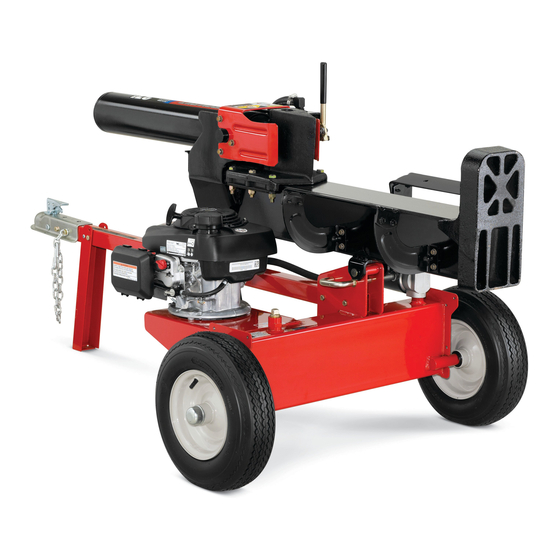
LS 27 TB — Log Splitter
WARNING
READ AND FOLLOW ALL SAFETY RULES AND INSTRUCTIONS IN THIS MANUAL
BEFORE ATTEMPTING TO OPERATE THIS MACHINE.
FAILURE TO COMPLY WITH THESE INSTRUCTIONS MAY RESULT IN PERSONAL INJURY.
TROY-BILT LLC, P.O. BOX 361131 CLEVELAND, OHIO 44136-0019
Printed In USA
Form No. 769-09000
(May 20, 2013)
Advertisement
Chapters
Table of Contents

Related Manuals for Troy-Bilt TB 27 LS


Summary of Contents for Troy-Bilt TB 27 LS
- Page 1 Safe Operation Practices • Set-Up • Operation • Maintenance • Service • Troubleshooting • Warranty ’ peratOr anual LS 27 TB — Log Splitter WARNING READ AND FOLLOW ALL SAFETY RULES AND INSTRUCTIONS IN THIS MANUAL BEFORE ATTEMPTING TO OPERATE THIS MACHINE. FAILURE TO COMPLY WITH THESE INSTRUCTIONS MAY RESULT IN PERSONAL INJURY.
-
Page 2: Table Of Contents
To The Owner Thank You Thank you for purchasing a Troy-Bilt Log Splitter. It was carefully If applicable, the power testing information used to establish engineered to provide excellent performance when properly the power rating of the engine equipped on this machine can be operated and maintained. -
Page 3: Safe Operation Practices
Important Safe Operation Practices WARNING! This symbol points out important safety instructions which, if not followed, could endanger the personal safety and/or property of yourself and others. Read and follow all instructions in this manual before attempting to operate this machine. Failure to comply with these instructions may result in personal injury. - Page 4 If your machine is equipped with an internal combustion Never fuel machine indoors. engine and is intended for use near any unimproved forest, Never remove gas cap or add fuel while the engine is brush, or grass covered land, the engine exhaust should be hot or running.
-
Page 5: Maintenance And Storage
When splitting in the vertical position, stabilize the log Do not alter this machine in any manner, alterations such before moving the control handle. Split as follows: as attaching a rope or extension to the control handle, or adding to the width or height of the wedge may result in Place log on the end plate and turn until it leans personal injury. - Page 6 Safety Symbols This page depicts and describes safety symbols that may appear on this product. Read, understand, and follow all instructions on the machine before attempting to assemble and operate. Symbol Description READ THE OPERATOR’S MANUAL(S) Read, understand, and follow all instructions in the manual(s) before attempting to assemble and operate WARNING—...
-
Page 7: Assembly & Set-Up
Assembly & Set-Up Contents of Carton • One Log Splitter • One Tongue Assembly • One Operator’s Manual • One Engine Operator’s Manual NOTE: This Operator’s Manual covers several models. Log splitter Remove the spring clip and clevis pin from the jack stand features may vary by model. - Page 8 Align the holes in the tongue with the holes in the tank Disconnect the dislodger from the beam weld bracket by bracket and secure with the hardware just removed. See removing the six hex screws. See Figure 3-4. Figure 3-2. NOTE: The high pressure hose, which runs from the gear pump to the bottom of the control valve, must be above Hex Screws...
- Page 9 Lift and slide the cylinder up to the top of beam and into Cut the metal strap securing the log splitter to the bottom the weld brackets. See Figure 3-6. of the crate and remove the wood under the engine and/or any other wood, then roll the log splitter off the bottom of the shipping crate.
- Page 10 Set-Up Check the fluid level using the dipstick. See Figure 3-9. Do not overfill. Gas and Oil Fill-Up NOTE: Approved fluids include Shell Tellus® S2 M 32 Hydraulic Fluid, Dexron® III/Mercon® automatic transmission fluid, Pro- Service the engine with gasoline and oil as instructed in the engine Select™...
-
Page 11: Controls & Features
Controls & Features Control Handle Cylinder Log Dislodger Horizontal Beam Lock Tongue Beam Assembly End Plate Wedge Jack Stand Tray Vertical Beam Lock Figure 4-1 Wedge NOTE: This Operator’s Manual covers several models. Log splitter features may vary by model. Not all features in this manual are The wedge is used to split the wood. -
Page 12: Operation
Operation Starting & Stopping the Engine To lock the beam in the vertical position, pull out on the vertical beam lock and rotate it to secure the beam. See Refer to the Engine Operator’s manual packed with your log Figure 5-2. splitter for instructions on starting and stopping the engine. - Page 13 Using the Control Handle Splitting the Wood The control handle has three positions. See Figure 5-4. Start the engine as instructed in the Engine Operator’s manual included with the log splitter. Place the log against the end plate and only split the wood Neutral Reverse in the direction of the grain.
- Page 14 Operating Tips Transporting the Log Splitter WARNING! Do not tow faster than 45mph and Always: check the local, state and federal requirements Use clean fluid and check the fluid level regularly. before towing on any public road. Use an approved hydraulic fluid. Approved fluids include Shell Tellus®...
-
Page 15: Maintenance & Adjustment
Maintenance & Adjustments WARNING! If your engine has a vertical set-up shown in Figure 6-2, Do not make any adjustments without refer to Figure 6-2 for changing the hydraulic fluid. stopping the engine, disconnecting the spark plug wire, grounding it against the engine and relieving the hydro system pressure. - Page 16 Hose Clamps Reinstall the cylinder, hoses, pumps, filter and suction hose. Tighten the hose clamps to 50-60 in-lbs. Check the clamps on the return hose before each use and check Check the fluid level using the dipstick. Do not overfill. the clamps on the suction hose once a season.
-
Page 17: Service
Service Flexible Pump Coupler Install the nylon “spider” onto the engine coupling half. Install the pump coupling half and key on the pump shaft. The flexible pump coupler is a nylon “spider” insert, located Rotate the coupling half until the set screw faces down. Do between the pump and the engine shaft. -
Page 18: Troubleshooting
Troubleshooting Problem Cause Remedy Cylinder rod will not move 1. Broken drive shaft. 1. See authorized service dealer. 2. Shipping plugs left in hydraulic hoses. 2. Disconnect hydraulic hoses, remove shipping plugs, reconnect hoses. 3. Set screws in coupling not adjusted properly. 3. - Page 19 Problem Cause Remedy Wood will not split or wood 1. Small gear section damaged. 1. See authorized service dealer. splits too slowly 2. Pump check valve leaking. 2. See authorized service dealer. 3. Excessive pump inlet vacuum. 3. Make certain pump inlet hoses are clear and unblocked.
-
Page 20: Replacement Parts
Replacement Parts Component Part Number and Description 737-0348A Vented Dipstick 735-04103 Spider Bushing 718-04395 Coupling, .875 718-04392 Coupling, .500 710-1842A Set Screw 723-0405 Hydraulic Oil Filter 737-04308 Inlet Filter 727-04290 Inlet Hose 727-04288 Hydro Hose 727-0443 Return Hose 727-04362 Hydro Hose 726-0132 Hose Clamp 634-0186 Complete Wheel, 16.0 x 4.8 x 8.0... - Page 21 Notes...
- Page 22 10— n ection oteS...
- Page 23 10 — n ection oteS...
-
Page 24: Warranty
MANUFACTURER’S LIMITED WARRANTY FOR The limited warranty set forth below is given by Troy-Bilt LLC with Routine maintenance items such as lubricants, filters, blade respect to new merchandise purchased and used in the United States sharpening, tune-ups, brake adjustments, clutch adjustments, and/or its territories and possessions, and by MTD Products Limited deck adjustments, and normal deterioration of the exterior finish with respect to new merchandise purchased and used in Canada and/... - Page 25 Medidas importantes de seguridad • Configuración • Funcionamiento • Mantenimiento • Servicio • Solución de problemas • Garantía anual del peradOr LS 27 TB — Máquina rompe troncos ADVERTENCIA LEA Y RESPETE TODAS LAS NORMAS DE SEGURIDAD E INSTRUCCIONES INCLUIDAS EN ESTE MANUAL ANTES DE PONER EN FUNCIONAMIENTO ESTA MÁQUINA.
- Page 26 Al propietario Gracias Gracias por comprar una MTD máquina rompe troncos. La estándar sin previo aviso y sin generar responsabilidad por misma ha sido diseñada cuidadosamente para brindar excelente obligaciones de ningún tipo. rendimiento si se la opera y mantiene correctamente. En su caso, los datos de prueba de potencia utilizados para Por favor lea todo este manual antes de operar el equipo.
-
Page 27: Medidas Importantes De Seguridad
Medidas importantes de seguridad ADVERTENCIA: La presencia de este símbolo indica que se trata de instrucciones de seguridad importantes que se deben respetar para evitar poner en peligro su seguridad personal y/o material y la de otras personas. Lea y cumpla todas las instrucciones de este manual antes de intentar operar esta máquina. - Page 28 Si la máquina está equipada con un motor de combustión Utilice sólo los recipientes para gasolina autorizados. interna y existe la intención de usarla cerca de un terreno Apague todos los cigarrillos, cigarros, pipas y otras agreste cubierto de bosque, arbustos o pasto, el escape del fuentes de ignición.
- Page 29 Use únicamente la mano derecha para operar los controles. Periódicamente controle que todas las tuercas y pernos, abrazaderas de mangueras y accesorios hidráulicos estén Nunca intente cortar más de un tronco a la vez. ajustados, para verificar que el equipo se encuentra en Para los registros que no están cortados en ángulo recto, el condiciones de trabajo seguras.
- Page 30 Símbolos de seguridad En esta página se presentan y describen los símbolos de seguridad que pueden aparecer en este producto. Lea, entienda y cumpla todas las instrucciones incluidas en la máquina antes de intentar realizar el montaje de la unidad y utilizarla. Símbolo Descripción LEA LOS MANUALES DEL OPERADOR...
-
Page 31: Montaje Y Configuración
Montaje y Configuración Contenido de la caja • Una máquina rompetroncos • Un montaje de lengüeta • Un Manual del operador • Un Manual del operador del motor NOTE: Ce manuel utilisateur couvre plusieurs modèles. Retire del gato que está sobre la lengüeta la abrazadera de Caractéristiques máquina rompe troncos peut varier selon le resorte y el pasador de horquilla y luego gire el gato hacia modèle. - Page 32 Alinee los orificios de la lengüeta con los orificios del Desconecte el liberador del soporte soldado de vigueta soporte del tanque y fíjela con los elementos de ferretería retirando los seis tornillos hexagonales. Vea la Figura 3-4. que se acaban de retirar. Vea la Figura 3-2. Tornillos NOTA: La manguera de alta presión, que se extiende desde de cabeza...
- Page 33 Levante y deslice el cilindro hacia arriba hasta el tope de la Corte la tira de metal que sujeta la máquina rompetroncos vigueta y dentro de los soportes soldados. Vea la Figura 3-6. a la base de la aja y extraiga la madera que está debajo del motor y/o cualquier otra madera, luego haga rodar la máquina fuera de la base de la caja de embalaje.
- Page 34 Presión de los neumáticos Desconecte la bujía y cebe la bomba tirando del arrancador de retroceso hasta el máximo. Repita este paso aproximada- La presión de operación máxima recomendada es 30 psi. En mente 10 veces. ninguna circunstancia supere la presión en psi recomendada por Vuelva a conectar el cable de la bujía y arranque el motor el fabricante.
-
Page 35: Controles Y Características
Controles y Características Manija de control Liberador de Cilindro la madera Bloqueo de la viga horizontal Lengüeta Montaje de la vigueta Fin del mural Cuña Gato Bandeja de troncos Vertical: Vigueta Tuerca Cuña NOTE: Ce manuel utilisateur couvre plusieurs modèles. Caractéristiques máquina rompe troncos peut varier selon le La cuña se usa para cortar la madera. -
Page 36: Funcionamiento
Funcionamiento Arranque y detención del motor Para trabar la vigueta en posición vertical, tire del bloqueo de vigueta vertical hacia afuera y gírelo para Consulte el manual del operador del motor embalado con la ajustar la vigueta. Vea la Figura 5-2. máquina rompetroncos por las instrucciones sobre cómo arrancar y detener el motor. - Page 37 Uso de la manija de control Cómo cortar madera La manija de control tiene tres posiciones. Vea la Figura 5-4. Ponga en marcha el motor como se indica en el manual del operador del motor que se incluye con la máquina Neutral rompetroncos.
- Page 38 Consejos de operación Transporte de la máquina rompetroncos Baje la vigueta a la posición horizontal. Asegúrese de que la Siempre: vigueta esté trabada firmemente con el bloqueo de vigueta horizontal. Use líquido limpio y controle el nivel de líquido periódicamente. Retire la abrazadera de resorte y el pasador de horquilla del gato.
-
Page 39: Mantenimiento Y Ajustes
Maintenance & Adjustments ¡ADVERTENCIA! Si el motor tiene un motor horizontal de configuración se Siempre detenga el motor, muestra en la Figura 6-1, consulte la Figura 6-1 para cambiar el desconecte el cable de la bujía y haga masa contra aceite hidráulico. - Page 40 Con mucho cuidado desenrosque el filtro de entrada y Si Rellene el depósito necesario dentro del rango marcado limpiarlo con aceite penetrante. Vea la Figura 6-3. en la varilla. Vea la Figura 6-4. Varilla Filtro de entrada Sólo de fluidos hidráulicos Figura 6-3 Figura 6-4...
- Page 41 Almacenamiento fuera de temporada Si el rompe troncos no se usa por más de 30 días, prepárelo para su almacenamiento de la siguiente manera: ¡ADVERTENCIA! Nunca almacene la máquina con combustible en el tanque en un área del edificio donde los vapores puedan alcanzar una llama expuesta o chispas, o donde existan fuentes de ignición, tales como calentadores de agua, calefactores de ambientes, hornos, secadoras de...
-
Page 42: Servicio
Service Acoplador flexible de la bomba Deslizar el nuevo medio de acoplamiento del motor en el eje del motor hasta que el extremo del eje quede al ras con la parte El acoplador flexible de la bomba es un inserto de nylon “araña”, interior del medio de acoplamiento. -
Page 43: Solución De Problemas
Solución de Problemas Problema Causa Solución La varilla del cilindro no se 1. El eje de accionamiento está roto. 1. Consulte al distribuidor de servicio autorizado. mueve 2. Se han dejado los tapones de envío en las 2. Desconecte las mangueras hidráulicas, retire los mangueras hidráulicas. - Page 44 Problema Causa Solución La madera no se parte o se 1. La sección de engranajes pequeños está dañada. 1. Consulte al distribuidor de servicio autorizado. divide la madera con demasiada 2. La válvula de retención de la bomba tiene pérdidas. 2.
- Page 45 Notas...
- Page 46 9— n ección otaS...
- Page 47 9 — n ección otaS...
-
Page 48: Garantía
GARANTÍA LIMITADA DEL FABRICANTE PARA La siguiente garantía limitada es otorgada por Troy-Bilt LLC con Los artículos necesarios para el mantenimiento de rutina respecto a nuevos productos adquiridos y utilizados en Estados como por ejemplo lubricantes, filtros, afiladores de cuchillas, Unidos y/o sus territorios y posesiones, y por MTD Products Limited sincronización del motor, los ajustes de los frenos, del embrague con respecto a nuevos productos adquiridos y utilizados en Canadá...
Need help?
Do you have a question about the TB 27 LS and is the answer not in the manual?
Questions and answers