Troy-Bilt LS 33 TB Operator's Manual
Hide thumbs
Also See for LS 33 TB:
- Operator's manual (40 pages) ,
- Operator's manual (48 pages) ,
- Operator's manual (48 pages)
Advertisement
Safe Operation Practices • Set-Up • Operation • Maintenance • Service • Troubleshooting • Warranty
O
'
M
peratOr
s
anual
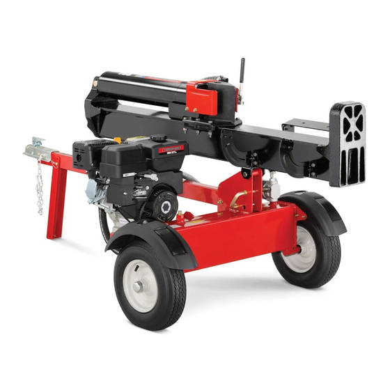
LS 33 TB — Log Splitter
WARNING
READ AND FOLLOW ALL SAFETY RULES AND INSTRUCTIONS IN THIS MANUAL
BEFORE ATTEMPTING TO OPERATE THIS MACHINE.
FAILURE TO COMPLY WITH THESE INSTRUCTIONS MAY RESULT IN PERSONAL INJURY.
TROY-BILT LLC, P.O. BOX 361131 CLEVELAND, OHIO 44136-0019
Printed In USA
Form No. 769-06755
(February 18, 2011)
Advertisement
Table of Contents

Related Manuals for Troy-Bilt LS 33 TB


Summary of Contents for Troy-Bilt LS 33 TB
- Page 1 READ AND FOLLOW ALL SAFETY RULES AND INSTRUCTIONS IN THIS MANUAL BEFORE ATTEMPTING TO OPERATE THIS MACHINE. FAILURE TO COMPLY WITH THESE INSTRUCTIONS MAY RESULT IN PERSONAL INJURY. TROY-BILT LLC, P.O. BOX 361131 CLEVELAND, OHIO 44136-0019 Printed In USA Form No. 769-06755...
-
Page 2: Table Of Contents
Choose from the options below: ◊ Visit us on the web at www.troybilt.com ◊ Call a Customer Support Representative at (800) 828-5500 or (330) 558-7220 ◊ Write us at Troy-Bilt LLC • P.O. Box 361131 • Cleveland, OH • 44136-0019... -
Page 3: Safe Operation Practices
Important Safe Operation Practices WARNING! This symbol points out important safety instructions which, if not followed, could endanger the personal safety and/or property of yourself and others. Read and follow all instructions in this manual before attempting to operate this machine. Failure to comply with these instructions may result in personal injury. - Page 4 If your machine is equipped with an internal combustion Never fuel machine indoors. engine and is intended for use near any unimproved forest, Never remove gas cap or add fuel while the engine is brush, or grass covered land, the engine exhaust should be hot or running.
-
Page 5: Maintenance And Storage
When splitting in the vertical position, stabilize the log Do not alter this machine in any manner, alterations such before moving the control handle. Split as follows: as attaching a rope or extension to the control handle, or adding to the width or height of the wedge may result in Place log on the end plate and turn until it leans personal injury. - Page 6 Safety Symbols This page depicts and describes safety symbols that may appear on this product. Read, understand, and follow all instructions on the machine before attempting to assemble and operate. Symbol Description READ THE OPERATOR’S MANUAL(S) Read, understand, and follow all instructions in the manual(s) before attempting to assemble and operate WARNING —...
-
Page 7: Assembly & Set-Up
Assembly & Set-Up Contents of Carton • One Log Splitter • One Operator’s Manual • One Engine Operator’s Manual WARNING! Crate Disassembly Do not remove the beam support or attempt to remove the machine from the crate until Use a pry bar or claw hammer to loosen and remove the after you have completed all assembly steps. - Page 8 Pull the beam lock outward, line it up with the hole in the Removing the Supports beam bracket and release the beam lock. See Fig 3-3. CAUTION: Do not attempt to move the logsplitter Fasten the tongue tube to the frame by reinstalling the two off of the crate base until after the crate supports three-inch hex screws removed earlier and tightly securing and plastic tie-straps have been removed.
- Page 9 Carefully reposition the logsplitter off of the crate by lifting Set-Up up on the tongue tube, near the hitch coupling, and slowly rotating the machine clockwise. See Fig. 3-6. Gas and Oil Fill-Up Service the engine with gasoline and oil as instructed in the engine manual packed with your log splitter.
- Page 10 NOTE: Approved fluids include Shell Tellus® S2 M 32 Hydraulic Fluid, Dexron® III/Mercon® automatic transmission fluid, Pro-Select™ AW-32 Hydraulic Oil or 10WAW-ISO viscosity grade 32 hydraulic oil. It is not recommended that fluids be mixed, to top off the reservoir tank during initial set-up use Shell Tellus®...
-
Page 11: Controls & Features
Controls & Features Control Dislodger Handle Hitch Coupling Log Tray Jack Stand Horizontal Vertical Beam Lock Beam Lock Dipstick Figure 4-1 Engine Controls Log Dislodger See the Engine Operator’s Manual for the location and function The log dislodger is designed to remove any partially split wood of the controls on the engine. -
Page 12: Operation
Operation Pre-Start Checklist Vertical Remove the dipstick and check hydraulic fluid level. Refill if necessary. Approved fluids include Shell Tellus® S2 M 32 Hydraulic Fluid, Dexron® III / Mercon® automatic transmission fluid, Pro-Select™ AW-32 Hydraulic Oil or 10WAW-ISO viscosity grade 32 hydraulic oil. Check the engine oil level. - Page 13 Return Wedge To Stop Wedge To Split Wood Horizontal Beam Lock Figure 5-3 Figure 5-4 Using the Control Handle Splitting the Wood The control handle has three positions. See Fig. 5-4. Start the engine as instructed in the Engine Operator’s manual included with the log splitter.
- Page 14 Operating Tips Transporting the Log Splitter Lower the beam to its horizontal position. Make certain the Always: beam is locked securely with the horizontal beam lock. Use clean fluid and check the fluid level regularly. Remove the spring clip and clevis pin from the jack stand. Use an approved hydraulic fluid.
-
Page 15: Maintenance & Adjustment
Maintenance & Adjustments WARNING! Allow the fluid to drain into a suitable container. Do not at any time make any adjustments without first stopping engine, Reinsert the filter and reconnect the hose. Fill the reservoir disconnecting spark plug wire and grounding it as instructed in the Assembly &... - Page 16 Off-Season Storage If the log splitter will not be used for more than 30 days, prepare for storage as follows: WARNING! Never store machine with fuel in the fuel tank inside of building where fumes may reach an open flame or spark, or where ignition sources are present such as hot water and space heaters, furnaces, clothes dryers, stoves, electric motors, etc.
- Page 17 Service Flexible Pump Coupler Align the pump coupling half with the nylon “spider” by rotating the engine using the starter handle. Slide the The flexible pump coupler is a nylon “spider” insert, located coupling half into place while guiding the three mounting between the pump and the engine shaft.
-
Page 18: Troubleshooting
Troubleshooting Problem Cause Remedy Engine fails to start Spark plug wire disconnected. Connect wire to spark plug. Fuel tank empty or stale fuel. Fill tank with clean, fresh gasoline. Choke, if equipped, not in CHOKE position. Move choke to CHOKE position. Faulty spark plug. - Page 19 Problem Cause Remedy Slow cylinder shaft speed Gear sections damaged. See authorized service dealer. while extending and Excessive pump inlet vacuum. Make certain pump inlet hoses are clear and retracting. unblocked-use short, large diameter inlet hoses. Slow engine speed. See authorized service dealer. Damaged relief valve.
-
Page 20: Replacement Parts
Replacement Parts Component Part Number and Description 737-0348A Vented Dipstick 735-04103 Spider Bushing 718-04395 Coupling, .875 718-04392 Coupling, .500 710-1842 Set Screw 723-0405 Hydraulic Oil Filter 737-04308 Inlet Filter 727-0451 Inlet Hose 727-04288 Hydro Hose 727-0443 Return Hose 727-04362 Hydro Hose 726-0132 Hose Clamp 634-0186... - Page 21 Notes...
- Page 22 Otes...
- Page 23 Otes...
-
Page 24: Warranty
MANUFACTURER’S LIMITED WARRANTY FOR The limited warranty set forth below is given by Troy-Bilt LLC with c. Service completed by someone other than an authorized service respect to new merchandise purchased and used in the United States dealer. and/or its territories and possessions, and by MTD Products Limited d.
Need help?
Do you have a question about the LS 33 TB and is the answer not in the manual?
Questions and answers