Troy-Bilt LS 27 Operator's Manual
Operation manual
Hide thumbs
Also See for LS 27:
- Operator's manual (44 pages) ,
- Operator's manual (40 pages) ,
- Operator's manual (48 pages)
Table of Contents
Advertisement
Safe Operation Practices • Set-Up • Operation • Maintenance • Service • Troubleshooting • Warranty
O
'
M
peratOr
s
anual
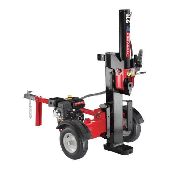
LS 27 TB — Log Splitter
WARNING
READ AND FOLLOW ALL SAFETY RULES AND INSTRUCTIONS IN THIS MANUAL
BEFORE ATTEMPTING TO OPERATE THIS MACHINE.
FAILURE TO COMPLY WITH THESE INSTRUCTIONS MAY RESULT IN PERSONAL INJURY.
TROY-BILT LLC, P.O. BOX 361131 CLEVELAND, OHIO 44136-0019
Printed In USA
Form No. 769-06118
(May 19, 2010)
Advertisement
Table of Contents

Related Manuals for Troy-Bilt LS 27


Summary of Contents for Troy-Bilt LS 27
- Page 1 READ AND FOLLOW ALL SAFETY RULES AND INSTRUCTIONS IN THIS MANUAL BEFORE ATTEMPTING TO OPERATE THIS MACHINE. FAILURE TO COMPLY WITH THESE INSTRUCTIONS MAY RESULT IN PERSONAL INJURY. TROY-BILT LLC, P.O. BOX 361131 CLEVELAND, OHIO 44136-0019 Printed In USA Form No. 769-06118...
-
Page 2: Table Of Contents
Choose from the options below: ◊ Visit us on the web at www.troybilt.com ◊ Call a Customer Support Representative at (800) 828-5500 or (330) 558-7220 ◊ Write us at Troy-Bilt LLC • P.O. Box 361131 • Cleveland, OH • 44136-0019... -
Page 3: Safe Operation Practices
Important Safe Operation Practices WARNING! This symbol points out important safety instructions which, if not followed, could endanger the personal safety and/or property of yourself and others. Read and follow all instructions in this manual before attempting to operate this machine. Failure to comply with these instructions may result in personal injury. - Page 4 If your machine is equipped with an internal combustion Never fuel machine indoors. engine and is intended for use near any unimproved forest, Never remove gas cap or add fuel while the engine is brush, or grass covered land, the engine exhaust should be hot or running.
-
Page 5: Maintenance And Storage
When splitting in the vertical position, stabilize the log Do not alter this machine in any manner, alterations such before moving the control handle. Split as follows: as attaching a rope or extension to the control handle, or adding to the width or height of the wedge may result in Place log on the end plate and turn until it leans personal injury. - Page 6 Safety Symbols This page depicts and describes safety symbols that may appear on this product. Read, understand, and follow all instructions on the machine before attempting to assemble and operate. Symbol Description READ THE OPERATOR’S MANUAL(S) Read, understand, and follow all instructions in the manual(s) before attempting to assemble and operate WARNING—...
-
Page 7: Assembly & Set-Up
Assembly & Set-Up Contents of Carton • One Log Splitter • One Tongue Assembly • One Operator’s Manual • One Engine Operator’s Manual WARNING! Remove the spring clip and clevis pin from the jack stand Use extreme caution unpacking this on the tongue and then pivot the jack stand towards the machine. - Page 8 Align the holes in the tongue with the holes in the tank Disconnect the dislodger from the beam weld bracket by bracket and secure with the hardware just removed. See removing the six hex screws. See Fig. 3-4. Fig. 3-2. NOTE: The high pressure hose, which runs from the gear pump to the bottom of the control valve, must be above Hex screws...
- Page 9 Cut the metal strap securing the log splitter to the bottom Lift and slide the cylinder up to the top of beam and into of the crate and remove the wood under the engine and/or the weld brackets. See Fig. 3-6. any other wood, then roll the log splitter off the bottom of the shipping crate.
- Page 10 Set-Up Check the fluid level using the dipstick. See Fig. 3-9. Do not overfill. Gas and Oil Fill-Up NOTE: Approved fluids include Shell Tellus® 32 Hydraulic Fluid, Dexron® III/Mercon® automatic transmission fluid, Service the engine with gasoline and oil as instructed in Pro-Select™...
-
Page 11: Controls & Features
Controls & Features Control Handle Cylinder Log Dislodger Horizontal Beam Lock Beam Assembly Tongue End Plate Wedge Jack Stand Tray Vertical Beam Lock Figure 4-1 Engine Controls Log Dislodger See the Engine Operator’s Manual for the location and function The log dislodger is designed to remove any partially split wood of the controls on the engine. -
Page 12: Operation
Operation Starting & Stopping the Engine To lock the beam in the vertical position, pull out on the vertical beam lock and rotate it to secure the Refer to the Engine Operator’s manual packed with your log beam. See Fig. 5-2. splitter for instructions on starting and stopping the engine. - Page 13 Using the Control Handle To stabilize the log, place your left hand on the side of the log opposite the beam as shown in Fig. 5-1. The control handle has three positions. See Fig. 5-4. WARNING! Never place a hand on the ends of the log, between the log or end plate and the splitting Neutral wedge.
-
Page 14: Operating Tips
Operating Tips Transporting the Log Splitter Lower the beam to its horizontal position. Make certain the Always: beam is locked securely with the horizontal beam lock. Use clean fluid and check the fluid level regularly. Remove the spring clip and clevis pin from the jack stand. Use an approved hydraulic fluid. -
Page 15: Maintenance & Adjustment
Maintenance & Adjustments WARNING! Carefully unthread the inlet filter and clean it with Do not make any adjustments without penetrating oil. See Fig. 6-2. stopping the engine, disconnecting the spark plug wire, grounding it against the engine and relieving the hydro system pressure. Always wear safety glasses during operation or while performing any adjustments or repairs. - Page 16 Beam If necessary Refill the reservoir within range marked on the dipstick. See Fig. 6-3. • Lubricate both sides of the beam (where it comes into contact with the splitting wedge), before each use, with engine oil. Dipstick Off-Season Storage If the log splitter will not be used for more than 30 days, prepare it for storage as follows: WARNING!
-
Page 17: Service
Service Flexible Pump Coupler Align the pump coupling half with the nylon “spider” by rotating the engine using the starter handle. Slide the The flexible pump coupler is a nylon “spider” insert, located coupling half into place while guiding the three mounting between the pump and the engine shaft. -
Page 18: Troubleshooting
Troubleshooting Problem Cause Remedy Cylinder rod will not move Broken drive shaft. See authorized service dealer. Shipping plugs left in hydraulic hoses. Disconnect hydraulic hoses, remove shipping plugs, reconnect hoses. Set screws in coupling not adjusted properly. See authorized service dealer. Loose shaft coupling. - Page 19 Problem Cause Remedy Wood will not split or wood Small gear section damaged. See authorized service dealer. splits too slowly Pump check valve leaking. See authorized service dealer. Excessive pump inlet vacuum. Make certain pump inlet hoses are clear and unblocked.
-
Page 20: Replacement Parts
Replacement Parts Component Part Number and Description 737-0348A Vented Dipstick 735-04103 Spider Bushing 718-04474 Coupling, .875 718-04392 Coupling, .500 710-1842 Set Screw 723-0405 Hydraulic Oil Filter 737-04308 Inlet Filter 727-04356 Inlet Hose 727-04288 Hydro Hose 727-0443 Return Hose 727-04362 Hydro Hose 726-0174 Hose Clamp 634-0186 Wheel Assembly, 16.0 x 4.8 x 8.0... - Page 21 Notes...
- Page 22 10— n ectiOn Otes...
- Page 23 10 — n ectiOn Otes...
-
Page 24: Warranty
MANUFACTURER’S LIMITED WARRANTY FOR The limited warranty set forth below is given by Troy-Bilt LLC with c. Service completed by someone other than an authorized service respect to new merchandise purchased and used in the United States dealer. and/or its territories and possessions, and by MTD Products Limited d.
Need help?
Do you have a question about the LS 27 and is the answer not in the manual?
Questions and answers