Table of Contents
Advertisement
®
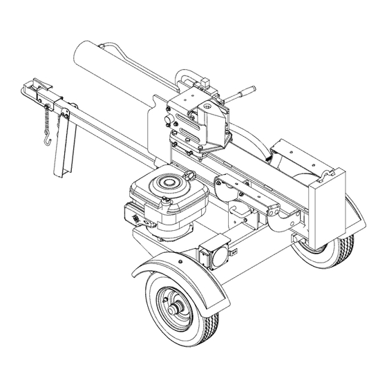
Operator's Manual
27 Ton
Log Splitter
Model 570
IMPORTANT:
Read safety rules and instructions
carefully
before operating
equipment.
Warning:
This unit is equipped with an internal combustion
engine and should not be used on or near any unimproved
forest-
covered, brush-covered
or grass-covered
land unless the engine's exhaust system is equipped with a spark arrester meeting
applicable local or state laws (if any). If a spark arrester is used, it should be maintained
in effective working order by the operator.
In the State of California the above is required by law (Section 4442 of the California Public Resources Code). Other states may have
similar laws. Federal laws apply on federal lands. A spark arrester for the muffler is available through your nearest engine authorized
service dealer or contact the service department,
P.O. Box 368022 Cleveland, Ohio 44136-9722.
TROY-BILT
LLC, P.O. BOX 361131
CLEVELAND,
OHIO 44136-0019
PRINTED IN U.S.A.
FORM NO. 769-01326
(7/2004)
Advertisement
Table of Contents
Troubleshooting

Related Manuals for Troy-Bilt 570


Summary of Contents for Troy-Bilt 570
- Page 1 ® Operator's Manual 27 Ton Log Splitter Model 570 IMPORTANT: Read safety rules and instructions carefully before operating equipment. Warning: This unit is equipped with an internal combustion engine and should not be used on or near any unimproved forest-...
-
Page 2: Customer Support
TABLEOFCONTENTS Content Page Content Page Important Safe Operation Practices Maintaining Your Log Splitter Assembling Your Log Splitter Storing Your Log Splitter Know Your Log Splitter Trouble Shooting Illustrated Parts List Operating Your Log Splitter Adjusting Your Log Splitter Warranty FINDINGMODELNUMBER This Operator's Manual is an important part of your new log splitter. -
Page 3: Section 1: Important Safeoperation P Ractices
SECTION 1: IMPORTANT SAFEOPERATION P RACTICES ARNING: This symbol points out important safety instructions which, if not followed, could endanger the personal safety and/or property of yourself and others. Read and follow all instructions in this manual before attempting to operate this machine. Failure to comply with these instructions may result in personal injury. -
Page 4: Your Responsibility
If gasoline is spilled, wipe it off the engine and Maintenance and Storage equipment, move machine to another area. Wait 5 Stop the engine, disconnect the spark plug and ground it minutes before starting the engine. against the engine before cleaning, or inspecting the Never store the machine or fuel container inside machine. -
Page 5: Section 2: Assembling Your Log Splitter
SECTION 2: ASSEMBLING YOUR LOG SPLITTER Unpacking fromCrate Attaching theTongue • With the log splitter still standing upright, remove • Pry top, sides, and ends off the crate. Set panels two hex bolts, lock washers, and hex nuts from the aside to avoid tire puncture or personal injury. -
Page 6: Preparingthelog Splitter
PreparingtheLog Splitter • Disconnect the log cradle from the beam on the side of the control valve. See Figure 4. • Lubricate the beam area (where the splitting wedge will slide) with engine oil; do not use grease. • Remove vented reservoir dipstick, which is located in front of the engine on top of the reservoir tank. -
Page 7: Section 3: Know Your Log Splitter
SECTION 3: KNOW YOUR LOG SPLITTER Compare the illustration in Figure 7 below with the controls on your log splitter, and get familiar with its features before starting to operate. Know how to stop the machine quickly in the event of an emergency. How it works Reverse "... -
Page 8: Section 4: Operating Y Our Logsplitter
SECTION 4: OPERATING Y OUR LOGSPLITTER BeforeEachUse WARNING: Read, understand, and follow all • Remove the dipstick and check hydraulic fluid level. instructions and warnings on the machine and Refill if necessary. in this manual before operating. • Check engine oil level. Refill if necessary. WARNING: Wear leather work gloves, •... -
Page 9: Operating Tips
• Tolockthebeam inthevertical p osition, pullouton Attempt to remove partially split wood from the thevertical beam lockandrotate it tosecure the wedge with your hands. Fully retract wedge to beam. S eeFigure 7. dislodge wood with log dislodger. • Stand infrontoftheunittooperate thecontrol handle andtostabilize thelog.SeeFigure 8A. -
Page 10: Section 5: Adjusting Your Log Splitter
If coupler hitch is too loose on ball: Turn adjustment nut one turn clockwise. ARNING: and check local, state, and federal Do not tow faster than 45mph Connect the safety chains to the towing vehicle. requirements before towing on any public road. Plug in the tail lights, if so equipped, to the tail light connector on the tow vehicle. - Page 11 • Remove three nuts and lock washers that secure Hydraulic Fluid the pump to the coupling shield. Two nuts are at the • Check the hydraulic fluid level in the log splitter bottom corners and one is in the top center. reservoir tank before each use.
-
Page 12: Section 7: Storing Your Logsplitter
SECTION 7: STORING YOUR LOGSPLITTER Prepare your log splitter for storage at the end of the • Drain fuel tank. Always drain fuel into approved season or if the log splitter will not be used for 30 days container outdoors, away from open flame. Be sure or more. -
Page 13: Hydraulic Troubleshooting
Hydraulic Troubleshooting Problem Cause Remedy Broken drive shaft. See authorized service dealer. Cylinder rod will not move Shipping plugs left in hydraulic Disconnect hydraulic hoses, remove hoses. shipping plugs, reconnect hoses. Set screws in coupling not adjusted See operator's manual for correct properly. -
Page 14: Section 9: Parts Listformodel 570
SECTION 9: PARTS LISTFORMODEL 570 16 13 \\\\ For Taillight. Ground Wire 48.. 81 \ 79 _ t If equipped... - Page 15 Model570 Ref. Ref. Part No. Part No. Part Description Part Description 718-0769 781-0686 Hydraulic Cylinder Log Tray Bracket 727-0634 681-0161 Hydraulic Tube Frame Assembly 710-1018 726-0214 Hex Cap Screw 1/2-20 x 2.75 Push Cap 732-0583 737-0192 90 Degree Solid Adapter Compression Spring 710-0521 Hex Bolt 3/8-16 x 3"...
- Page 16 MANUFACTURER'S LIMITED WARRANTY FOR: ® The limited warranty set forth below is given by Troy-Bilt LLC Troy-Bilt does not extend any warranty for products with respect to new merchandise purchased and used in the sold or exported outside of the United States, its United States, its possessions and territories.
Need help?
Do you have a question about the 570 and is the answer not in the manual?
Questions and answers