
Related Manuals for JAI CV-M9 GE


Summary of Contents for JAI CV-M9 GE
- Page 1 GigE Vision Digital 3CCD Progressive Scan RGB Color Camera CV-M9 GE Operation Manual Hardware Part 10 April 2007 /GJ Camera revision: Manual version: 1.0...
-
Page 2: Table Of Contents
CV-M9 GE - Table of Contents - 1. General......................3 2. Standard Composition ..................3 3. Main Features ....................3 4. Locations and Functions..................4 5. Pin Assignment....................5 5.1. 12-pin Multi-connector (DC-in/GPIO/Iris Video) ..........5 5.2. Digital Output Connector for Gigabit Ethernet ........... 5 6. - Page 3 CV-M9 GE 8.5.2. LVAL a-synchronous accumulation............29 8.5.3. Continuous operation ................ 30 8.5.4. Edge Pre-select Trigger Mode .............. 30 8.5.5. Pulse Width Control Trigger Mode ............32 8.5.6. Sequential Trigger Mode (EPS) ............. 33 8.5.7. Delayed Readout Mode (EPS, PWC)............34 8.5.8.
-
Page 4: General
For further information on GenICam please go to www.emva.org. As a programming application interface, JAI provides an SDK (Software Development Kit). This SDK includes software documentation, register information, code examples and objects such as Transport Layer and Device Drivers (Optimized Filter Driver and Standard Windows Stack). -
Page 5: Locations And Functions
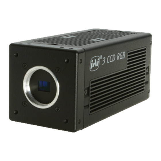
CV-M9 GE 4. Locations and Functions ⑨ 8-M3depth5 (depth0.2) ⑥ ⑤ ④ HI R OSE 12pin C onnector W.B. POWE R DC IN ② / TRIG / TRIG ⑦ GigE LINK ACT. ③ HONDAGigabit-Ethernrt Jac k ⑧ ① Lens mount of C-mount type. *1) RGB Prism with 3 x 1/3”... -
Page 6: Pin Assignment
CV-M9 GE 5. Pin Assignment 5.1. 12-pin Multi-connector (DC-in/GPIO/Iris Video) Type: HR10A-10R-12PB-01 (Hirose) male. Pin no. Signal Remarks (Seen from rear of camera.) +12 V DC input Iris video Only for Continuous mode LVDS + / TTL IN 1 LVDS - / TTL IN 2... -
Page 7: Gpio (Inputs And Outputs)
CV-M9 GE 6. GPIO (Inputs and outputs) 6.1. Overview All input and output signals pass through the GPIO (General Purpose Input and Output) module. The GPIO module consists of a Look-Up Table (LUT – Cross-Point Switch), 4 Pulse Generators and a 12-bit counter. -
Page 8: Inputs And Outputs Table
CV-M9 GE 6.2. Inputs and outputs table Signals Description diagram LVAL_IN LVAL (Line Valid) from camera timing circuit (See chapter 8.4 for timing relationship) DVAL IN DVAL from camera FVAL_IN FVAL (Frame Valid) from camera timing circuit (See chapter 8.4 for timing relationship) -
Page 9: Equivalent Circuit For Ttl 1 And 2 Inputs
CV-M9 GE 6.2.1. Equivalent circuit for TTL 1 and 2 inputs This circuit is for TTL IN 1 and TTL IN 2 through +3.3V pins 6 and 7 at the 12-pin Hirose connector. It is a DC- coupled input. 2.2K... -
Page 10: Equivalent Circuit For Ttl Out 1 And 2 Outputs
CV-M9 GE 6.2.4. Equivalent circuit for TTL OUT 1 and 2 outputs This circuit is for TTL OUT 1 and 2 through pins 8 and 9 at the Hirose 12-pin connector. The output is sent from a 75 ohm source which is a complementary Emitter-follower circuit. -
Page 11: 12Bit Counter
CV-M9 GE 6.3.3. 12-bit counter Address Internal Name Access Size Setting Value (and range) 0: 25MHz 0xB000 Clock source 1: Pixel Clock 0x000: N=1 0x001: N=2 0xB004 Divide by N 0x002: N=3 0xFFF: N=4096 6.3.4. Pulse generator (20 bit x 4) There are 4 pulse generators (designated 0 through 3) that can be used to create various timing scenarios by programming start point, endpoint, length and repeats. - Page 12 CV-M9 GE Address Internal Name Access Size Setting Value (and range) 0x00: Infinite 0x01: 1 time 0xB038 Repeat Count 2 0xFF: 255 times 0xB03C End point Counter 2 0x00001 to 0xFFFFF 0x00: Free Run 0x01: High Level Clear 0xB040 Counter Clear 2...
-
Page 13: Gpio Programming Examples
CV-M9 GE 6.4 GPIO programming examples 6.4.1 Trigger Phase Control 100clock delay to the input Trigger Address Register Value 0xA040 Trigger Mode 1 = EPS(Edge pre-select) 0xB000 Clock Choice 1 = Pixel Clock 0xB004 Counter Dividing Value 0 = Pass through... -
Page 14: Internal Trigger Generator
CV-M9 GE 6.4.2 Internal Trigger Generator Create a trigger signal and trigger the camera Address Register Value 0xA040 Trigger Mode 1 = EPS 0xB000 Clock Choice 1 = Pixel Clock 0xB004 Counter Dividing Value 963 = 1/964 dev(Line Rate) 0xB008... -
Page 15: Multi Een Control With Pwc
CV-M9 GE 6.4.3 Multi EEN Control with PWC Camera EEN converts to 3 pulses and feed camera in PWC mode Address Register Value 0xA040 Trigger Mode 2 = PWC(Pulse width control) 0xB000 Clock Choice 1 = Pixel Clock 0xB004 Counter Dividing Value... -
Page 16: Gige Vision Streaming Protocol (Gvsp)
CV-M9 GE 7. GigE Vision Streaming Protocol (GVSP) 7.1. Digital Video Output (Bit Allocation) Although the CV-M9GE is a digital camera, the image is generated by an analog component, the CCD sensor. There are three CCD sensors in this camera. One for each R, G and B channel. -
Page 17: Functions And Operations
8. Functions and Operations 8.1. GigE Vision Standard Interface The CV-M9 GE is designed in accordance with the GigE Vision standard. In transmits digital images over CAT5e or Cat6 Ethernet cables. All camera functions are also controlled via the GigE Vision interface. -
Page 18: Basic Functions
CV-M9 GE To ensure the integrity of packets transmitted from the camera is recommended to follow these simple guidelines: 1. Whenever possible use a peer-to-peer network. 2. When connecting several cameras going though a network switch, make sure it is capable of handling jumbo packets and that it has sufficient memory capacity. -
Page 19: White Balance (By Individual R, G And B Channel Shutter Settings)
CV-M9 GE Manual white balance By adjusting the Red (Register 0xA0C8); Blue (Register 0xA0CC) and Master Gain (Register 0xA0C4) gains settings, it is possible to achieve a proper white balance output from the camera for a wide range of color temperatures. The recommended method is to point the camera at a white target, and adjust gain settings until image on the screen matches the target. -
Page 20: Knee Function
CV-M9 GE 8.3.4. Knee function The video signal is digitized to 3x12-bit 1279 and the most significant 3x8 or 3x10-bit 1023 are presented at the output. By using a look-up table function it is possible to compress the video signal to change the 1/16 dynamic range. -
Page 21: Electronic Shutter
CV-M9 GE 8.3.6. Electronic Shutter The CV-M9GE has two conventional shutter functions, Preset Shutter and Programmable Exposure, as well as the GenICam standard “Exposure Time Abs” function: Preset shutter (Register 0xA004) 12 pre-set (fixed) shutter speeds, OFF (1/30); 1/60; 1/100; 1/120; 1/250; 1/500; 1/1,000;... -
Page 22: Color Bar For Test
CV-M9 GE Shutter and Mode matrix Preset Programmable RGB common RGB individual RGB common RGB individual Continuous 8.3.7. Color bar for test The CV-M9GE camera has a build in color bar generator. When it is activated, the output image will be as shown below. The RGB values are shown for both 8 and 10 bit output. -
Page 23: Sensor Layout And Timing
CV-M9 GE 8.4. Sensor Layout and timing 8.4.1. CCD Sensor Layout blank Read Out 1077 (Vertical) Optical Black Lines Reserved Lines Active Pixels 1024(H)x768(V) Reserved Lines Optical Black Lines 1420 Clock 1024 dumm blan k Read Fig. 15. CCD sensor layout Important Note: In GigE Vision, only Active Pixel Area is output through the GigE interface. -
Page 24: Horizontal Timing
CV-M9 GE 8.4.2. Horizontal timing 1ck = 33.750MHz (29.63ns/ck) 1 LVAL period 1420ck 1077ck 343ck LVAL FVAL Raising Edge FVAL Falling Edge FVAL 1328ck 86ck (20us) 590ck 676ck Exposure Period XEEN (Hirose 12pin) 45ck Dummy+ OB Reserved Reserved Effective Pixels... -
Page 25: Partial Scanning
CV-M9 GE 8.4.4. Partial Scanning 1L= 1420 C lock (42 .07us ) 4 9 2 L 1L = 42.07 μs 4 8 8 L FVAL LVAL H igh Speed F r o n t o f F r am e... -
Page 26: Vertical Binning
CV-M9 GE 1L ine = 1420 C lock (42 .07us ) 1 FVA L p e r i o d 2 7 6 L 2 7 2 L FVAL LVAL H igh Speed F r o n t o f F r a m e... - Page 27 CV-M9 GE 1 FVAL Pe r iod F V A L 3 9 6 L L V A L 3 9 2 L FVAL LVAL 0 . 5 L E xpo su re Pe r iod XEEN ( H i rose 12p in )
-
Page 28: Operation Modes
CV-M9 GE 8.5. Operation Modes This camera can operate in 5 primary modes. 1. Continuous Mode Pre-selected exposure. 2. Edge Pre-select Mode (EPS) Pre-selected exposure. 3. Pulse Width Control Mode (PWC) Pulse width controlled exposure. 4. Sequential Trigger Pre-selected exposure (EPS) 5. - Page 29 CV-M9 GE Edge Pre-Select Mode : Full Frame 1L = 1420C l ock ( 42. 07us) Ext . Tr i g FVAL LVAL Exposur e Pr i od XEEN ( H i r ose 12pi n) 1. 5L ( Exposur e)
-
Page 30: Lval A-Synchronous Accumulation
CV-M9 GE 8.5.2. LVAL a-synchronous accumulation In LVAL a-synchronous mode, the accumulation will start immediately after the trigger leading edge. The exposure start delay is 9.7 μsec. (In V-binning mode, this delay will be 39.7 μsec) In EPS mode the exposure stops 0.5 L after the selected shutter time, (in number of LVAL). -
Page 31: Continuous Operation
CV-M9 GE 8.5.3. Continuous operation For applications not requiring asynchronous external trigger, but where a continuous stream of images is required, this mode should be used. In this mode it possible to use an auto-iris lens (video drive). The CV-M9GE provides an auto-iris lens video signal at pin 4 of the 12-pin Hirose connector. -
Page 32: Image Quality
CV-M9 GE In EPS trigger mode, R, G and B exposure can be set individually. Provided the gain in each channel is set to the same value, this function allows white balance to be achieved with the same noise level (S/N ratio) for all channels. Please note that extreme differences in exposure time, e.g. -
Page 33: Pulse Width Control Trigger Mode
CV-M9 GE 8.5.5. Pulse Width Control Trigger Mode In this mode the accumulation time is equal the trigger pulse width. Here it is possible to have long time exposure. The maximum recommended time is < 2 second. The accumulation can be LVAL synchronous or LVAL a-synchronous. -
Page 34: Sequential Trigger Mode (Eps)
CV-M9 GE 8.5.6. Sequential Trigger Mode (EPS) Shutter, Gain and ROI values can be preset for up to 10 sequences. Along with every trigger input, the image data with the preset sequence is output as described below. Trigger Sequence Sequence 1... -
Page 35: Delayed Readout Mode (Eps, Pwc)
CV-M9 GE Important Note for using this mode 1. When this mode is used, it is necessary to set "Video Sending Flag" to OFF at first and then set the trigger mode to "Continuous" (Register 0xA040 to 0). The shutter mode must then be set at Individual Shutter (0xA000 set to 2) regardless of the trigger modes. -
Page 36: Smear-Less Mode
CV-M9 GE 8.5.8. Smear-less Mode This function will reduce the unwanted smear signal from a highlighted scene when a short exposure time is used. It works in EPS and PWC trigger modes, but a dummy readout is performed before the active accumulation is started. It will remove the smear above the highlighted parts in the image, but there is still smear left below highlighted areas. -
Page 37: Operation Mode And Functions Matrix
CV-M9 GE 8.6. Operation Mode and Functions matrix Shutter Partial Smear- LVAL Auto Iris Mode Preset / Binning (Value) Scanning less Sync/Async output Program. 0x00 Continuous applicable Note 2. Edge Pre- 0x01 select (EPS) Pulse Width 0x02 Control applicable (PWC) -
Page 38: Register Map
CV-M9 GE 9. Register Map The below table provides detailed information for the hardware registers used for controlling the camera and obtaining information on the status of the camera. The content of this register map is also found in the XML file, as stipulated by the GenICam standard. - Page 39 CV-M9 GE number of available stream number of stream This camera only 0x0904 channel channels has 1 Bit 31:multiple read This is a capability register Bit 30:WRITEMEM indicating which one of the 0x0934 GVCP capability non-mandatory GVCP commands 29:ACKETRESEND are supported by this Bit 28:EVENT device.
- Page 40 CV-M9 GE Standard camera functions registers: Value / Range of Default Address Function Description value value 0= Preset shutter (RGB common) Sets exposure time for image 1= Programmable capture. exposure (RGB Mode 0 and 1 are for common common) 0xA000 Shutter mode RGB setting.
- Page 41 CV-M9 GE 0= OFF 0xA084 Vertical Binning 2 line binning 1= ON 0xA08C Color test pattern 0=Off, 1=On 0=Manual/One push 1=Continuous AWB 0xA0C0 White Balance 2=3200K 3=4600K 4=5600K 0xA0C4 Master Gain Level -132 to +429 0 0xA0C8 Gain level for Red...
- Page 42 CV-M9 GE 0=Factory area 1=User area1 Allow the user to recall all 0xA180 Load Settings 2=User area2 camera settings. 3=User area3 1=User area1 Allows use to save all camera Save Settings into 0xA184 2=User area2 settings. Last used area number...
- Page 43 CV-M9 GE 0xA360 Sequence Shutter B-5 0 to 791 Pre-program Blue-5 shutter 0xA364 Sequence Shutter B-6 0 to 791 Pre-program Blue-6 shutter 0xA368 Sequence Shutter B-7 0 to 791 Pre-program Blue-7 shutter 0xA36C Sequence Shutter B-8 0 to 791 Pre-program Blue-8 shutter...
- Page 44 CV-M9 GE 0xA424 ROI1 Size Y Height H.Max 0xA428 ROI1 Offset X Horizontal offset 0xA42C ROI1 Offset Y Vertical offset 0xA430 ROI2 Size X Width WidthMax Height 0xA434 ROI2 Size Y Height 0xA438 ROI2 Offset X Horizontal offset 0xA43C ROI2 Offset Y...
- Page 45 CV-M9 GE 0xA848 Seq. ROI size-Y 7 ROI1 size y-7 0xA84C Seq. ROI size-Y 8 ROI1 size y-8 0xA850 Seq. ROI size-Y 9 ROI1 size y-9 0xA854 Seq. ROI size-Y 10 ROI1 size y-10 0xA858 Seq. ROI offset-X 1 ROI1 offset x-1 0xA85C Seq.
- Page 46 CV-M9 GE 0x00: infinite 0x01: 1 time Defines the number of repeats 0xB010 Repeat, Counter 0 (loops) 0xFF: 255 times Defines the end point of the 0xB014 End point Counter 0 0x00001 to 0xFFFFF counter Free Run High Level Clear...
- Page 47 CV-M9 GE 0x06:HIROSE TTL IN 3 Selector 0xB06C 0x07:HIROSE LVDS IN Pulse Generator 0 0x09:SOFT TRIG 0 Selector 0x0D:Pulse Gen. 0 0xB070 Pulse Generator 1 0x0E:Pulse Gen. 1 0x0F:Pulse Gen. 2 Selector 0xB074 0x10:Pulse Gen. 3 Pulse Generator 2 0x7F:No Connection...
-
Page 48: External Appearance And Dimensions
Note: Rear protrusion on C-mount lens must be less than 4.0mm Fig. 31. Outline. 11. Specifications 11.1. Spectral response The shown responses are for prism and CCD sensors combined. Wave length (nm) Wave length (nm) Fig. 31. Spectral response for CV-M9 GE - 47 -... -
Page 49: Specification Table
CV-M9 GE 11.2. Specification table Specifications CV-M9GE Scanning system Progressive Frame rate 30 fps (792 lines per frame) Line frequency 23.768 kHz (1420 clk per line) V binning 19.622 kHz (1720 clk per line) Pixel frequency 33.75 MHz CCD sensors 3 x 1/3”... -
Page 50: Appendix
CV-M9 GE 12. Appendix 12.1. Precautions Personnel not trained in dealing with similar electronic devices should not service this camera. The camera contains components sensitive to electrostatic discharge. The handling of these devices should follow the requirements of electrostatic sensitive components. -
Page 51: References
CV-M9 GE 12.3. References 1. This manual can for CV-M9 GE can be downloaded from www.jai.com 2. Datasheet for CV-M9 GE can be downloaded from www.jai.com 3. Specifications for the CCD sensor Sony ICX-204AL can be found on www.jai.com - 50 -... -
Page 52: Index
CV-M9 GE Index Auto Iris Lens ........21 inter-packet delay........17 Basic functions ........17 Lens mount ........4, 38 binning ....... 3, 25, 26, 29, 34, 38 LVDS ........5, 7, 8, 9, 38 Bit Allocation ........15 Blemishes ......... 39 network interface cards (NICs) ....16... -
Page 53: User's Record
Company and product names mentioned in this manual are trademarks or registered trademarks of their respective owners. JAI A-S cannot be held responsible for any technical or typographical errors and reserves the right to make changes to products and documentation without prior notification.
Need help?
Do you have a question about the CV-M9 GE and is the answer not in the manual?
Questions and answers