
Related Manuals for JAI 141MCL-RA


Summary of Contents for JAI 141MCL-RA
- Page 1 User's Manual CM-141MCL/141MCL-RA CM-141PMCL/141PMCL-RA CB-141MCL/141MCL-RA CB-141PMCL/141PMCL-RA Digital Monochrome / Color Progressive Scan Camera Document Version: Ver.1.2 CM/CB-141MCL_Ver.1.2_Feb2010 1001E-1002...
-
Page 2: Warranty
JAI Ltd., Japan and may only be used by the purchasers of the product. JAI Ltd., Japan makes no warranty for the use of its product and assumes no responsibility for any errors which may appear or for damages resulting from the use of the information contained herein. - Page 3 Supplement The following statement is related to the regulation on “ Measures for the Administration of the control of Pollution by Electronic Information Products “ , known as “ China RoHS “. The table shows contained Hazardous Substances in this camera. mark shows that the environment-friendly use period of contained Hazardous Substances is 15 years.
- Page 4 Supplement The following statement is related to the regulation on “ Measures for the Administration of the control of Pollution by Electronic Information Products “ , known as “ China RoHS “. The table shows contained Hazardous Substances in this camera. mark shows that the environment-friendly use period of contained Hazardous Substances is 15 years.
-
Page 5: Table Of Contents
CM-141MCL/PMCL/RA / CB-141MCL/PMCL/-RA General ... 4 Camera nomenclature ... 4 Main Features ... 5 Locations and Functions ... 6 4.1. CM-141MCL/CB-141MCL ... 6 4.2. CM-141PMCL/CB-141PMCL ... 7 Pin Assignment ... 8 12-pin Multi-connector (DC-in/GPIO/Iris Video) ... 8 Digital Output Connector for Mini CameraLink ... 8 5.2.1 CM-141MCL/-RA and CB-141MCL/-RA ... - Page 6 CM-141MCL/PMCL/-RA / CB-141MCL/PMCL/-RA Camera Control Tool for CM-141 MCL / CB-141 MCL ... 34 Camera Control Tool Interface ... 34 8.1.1 Camera Control Tool Bar ... 34 The About Window ... 34 Communication Window ... 35 Camera Control Window ... 36 Using the Camera Control Tool ...
-
Page 7: General
Hereafter, CM-141MCL/CB-141MCL will represent a whole series except for specific descriptions. The CM-141MCL and CB-141MCL are JAI C3 Compact series digital cameras utilizing a Mini Camera Link interface. Both standard optical configurations (CM-141MCL/CB-141MCL) and right angle configurations (CM-141MCL-RA/CB-141MCL-RA) are available. Also, versions with Power over Mini Camera Link are available as CM/CB-141PMCL and CM/CB-141PMCL-RA. -
Page 8: Main Features
CM-141MCL/PMCL/-RA / CB-141MCL/PMCL/-RA 3. Main Features Member of C3 Compact camera series Mini Camera Link interface 1392 (h) x 1040 (v) 6.45 µm square pixels 2/3 inch progressive scan – monochrome and Bayer mosaic color versions ... -
Page 9: Locations And Functions
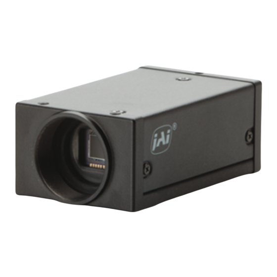
CM-141MCL/PMCL/RA / CB-141MCL/PMCL/-RA 4. Locations and Functions 4.1. CM-141MCL/CB-141MCL ② ① 1. Lens mount 2. CCD sensor 3. 26-pin multi connector 4. 12-pin connector 5. LED 6. Mounting holes *1) Note: Rear protrusion on C-mount lens must be less than 10.0mm. *2) Note: When an Mini Camera Link cable is connected to the camera, please do not excessively tighten screws by using a screwdriver. -
Page 10: Cm-141Pmcl/Cb-141Pmcl
CM-141MCL/PMCL/-RA / CB-141MCL/PMCL/-RA 4.2. CM-141PMCL/CB-141PMCL C mount ① 1. Lens mount 2. CCD sensor 3. 26-pin multi connector 4. LED 5. Mounting holes *1) Note: Rear protrusion on C-mount lens must be less than 10.0mm. *2) Note: When an Mini Camera Link cable is connected to the camera, please do not excessively tighten screws by using a screwdriver. -
Page 11: Pin Assignment
CM-141MCL/PMCL/RA / CB-141MCL/PMCL/-RA 5. Pin Assignment 5.1 12-pin Multi-connector (DC-in/GPIO/Iris Video) Type: HR10A-10R-12PB (Hirose) male. (Seen from the rear of camera) Fig.3. 12-pin connector. Note: 12-pin connector is only present on CM-141MCL/-RA and CB-141MCL/-RA. 5.2 Digital Output Connector for Mini Camera Link Type: 26-pin SDR connector(3M or Honda type) 5.2.1 CM-141MCL/-RA and CB-141MCL/-RA Fig.4. -
Page 12: Cm-141 Pmcl /-Ra And Cb-141 Pmcl/-Ra
CM-141MCL/PMCL/-RA / CB-141MCL/PMCL/-RA 5.2.2 CM-141 PMCL /-RA and CB-141 PMCL/-RA Fig.5. Mini-CL connector Important Note for PMCL version CM-141 PMCL/-RA and CB-141 PMCL/-RA cameras feature “Safe Power” circuit which is stipulated by the PoCL standard. This circuit is used to verify the presence of camera and PoCL cable before the frame grabber provides power. -
Page 13: Input And Output Circuits
This can be selected by a DIP switch located on the rear board. As changing the position requires removal of the circuit board, it is necessary to consult with JAI sales representatives. Factory default is complementary emitter followers. EEN is also found in Camera Link. -
Page 14: Camera Link Interface
CM-141MCL/PMCL/-RA / CB-141MCL/PMCL/-RA 5.4.4 Camera Link interface The digital video is available via Camera Link, with 8-,10- or 12-bit pixel depth, using the CL Base configuration. The digital output signals follow the Camera Link standard using Channel Link chip sets. The data bits from the digital video, FVAL, LVAL, DVAL and EEN are multiplexed into the twisted pairs, which are a part of the Camera Link. -
Page 15: Video Output Bit Allocation
CM-141MCL/PMCL/RA / CB-141MCL/PMCL/-RA 5.4.5 Video Output Bit allocation CCD out Black Setup 3.6%, 25mV 300mV 100% 342mV↑ 114% 1023 Black Level Analog Out [mV] Fig.10. Digital output (10bit output) Analogue Out (Equivalent) 8bit 8LSB 700mV 222LSB 255LSB 800mV White Clip Level 100% Level Digital Out 10bit... -
Page 16: Functions And Operations
CM-141MCL/PMCL/-RA / CB-141MCL/PMCL/-RA 6. Functions and Operations 6.1. Basic functions The CM-141MCL and CB-141MCL cameras are progressive scan cameras with 12-, 10- or 8-bit video output via a Mini Camera Link interface. The cameras have 2/3, 1/2, 1/4 or 1/8 partial scanning or variable partial scanning for faster frame rates. -
Page 17: Cb-141Mcl Bayer Mosaic Filter
CM-141MCL/PMCL/RA / CB-141MCL/PMCL/-RA 6.1.2 CB-141MCL Bayer mosaic filter CB-141MCL is a color camera based on a CCD sensor with a Bayer RGB color mosaic. The color image reconstruction is done in the host PC. The color sequence in the video signal is the same for all scanning formats. - Page 18 CM-141MCL/PMCL/-RA / CB-141MCL/PMCL/-RA Image Height Image start line/end line How to calculate total line number and frame rate in variable partial scan mode Variable partial scan The start line setting Read out height Total lines = OB period in the upper part of the frame (L) + Fast Dump period in the upper part of the frame (L) + Effective image period (L) + Fast dump period in the lower part of frame(L) Where, OB period in the upper part of the frame...
-
Page 19: Electronic Shutter
CM-141MCL/PMCL/RA / CB-141MCL/PMCL/-RA 6.1.4 Electronic Shutter CM-141MCL / CB-141MCL has conventional shutter functions such as preset shutter and programmable shutter as well as a new function of fine exposure. Preset Shutter 9 steps of preset shutter are available: OFF (1/30); 1/60,1/100,1/250,1/500,1/1,000,1/2,000, 1/4,000,1/8,000,1/10,000 sec. -
Page 20: Auto-Iris Lens Video Output (12-Pin Hirose Connector)
CCD Out [mV] Fig. 15. Iris Video 6.1.6 Auto-detect LVAL-sync / async accumulation This function replaces the manual setting found in older JAI cameras. Whether accumulation is synchronous or asynchronous in relationship to LVAL depends on the timing of the trigger input. -
Page 21: Rear Panel Indicator
CM-141MCL/PMCL/RA / CB-141MCL/PMCL/-RA 6.1.7 Rear panel indicator. The rear panel mounted LED provides the following information: Power /Trig LED Amber: Power connected – initiating Steady green: Camera is operating in continuous mode Flashing green: The camera is receiving an external trigger ... -
Page 22: Sensor Layout And Timing
CM-141MCL/PMCL/-RA / CB-141MCL/PMCL/-RA 6.2. Sensor Layout and timing 6.2.1 CCD Sensor Layout The CCD sensor layout with respect to pixels and lines used in the timing and video full frame read out is shown below. Effective Video Output 1392 (H) x 1040 (V) Pixel (1,1) Important Note: By using Optical Black (OB) transfer mode, the user can select whether to include optical black pixels in the image stream. -
Page 23: Horizontal Timing
CM-141MCL/PMCL/RA / CB-141MCL/PMCL/-RA 6.2.2 Horizontal timing The LVAL period is shown for normal continuous mode. 1 LVAL 1830 clk=31.551 us 1clk=17.241 ns LVAL DATA OUT DVAL 6.2.3 Vertical timing The FVAL period for normal continuous mode full scan is shown. Valid data 1392ck 1432ck... -
Page 24: Partial Scanning
CM-141MCL/PMCL/-RA / CB-141MCL/PMCL/-RA 6.2.4 Partial Scanning The FVAL period is shown for 1/2 partial scan in normal continuous mode. Vertical Timing The diagram and table below provide vertical timing information for the fixed partial scan settings 1/2, 1/4, 1/3 and 2/3. Values for vertical timing in partial scan continuous mode. -
Page 25: Vertical Binning
By activating this function, the frame rate is increased to 50.18 fps. This function is available only for CM-141MCL/141MCL-RA. Important Note Vertical Binning cannot be used together with Partial Scanning. -
Page 26: Operation Modes
CM-141MCL/PMCL/-RA / CB-141MCL/PMCL/-RA Vertical timing Fig.25 Vertical Timing for Vertical Binning 6.3. Operation Modes This camera can operate in 5 primary modes. 1. Continuous Mode 2. Edge Pre-select Mode (EPS) 3. Pulse Width Control Mode (PWC) 4. Reset Continuous Trigger Mode(RCT) Pre-select exposure 5.Smearless EPS Mode 6.3.1 Continuous operation For applications not requiring asynchronous external triggering, this mode should be used. -
Page 27: Edge Pre-Select (Eps) Trigger Mode
CM-141MCL/PMCL/RA / CB-141MCL/PMCL/-RA 6.3.2 Edge Pre-select (EPS) Trigger Mode An external trigger pulse initiates the capture, and the exposure time (accumulation time) is the fixed shutter speed set by registers. The accumulation can be LVAL synchronous or LVAL asynchronous. The resulting video signal will start to be read out after the selected shutter time. -
Page 28: Pulse Width Control (Pwc) Trigger Mode
CM-141MCL/PMCL/-RA / CB-141MCL/PMCL/-RA LVAL async timing Fig.27 Edge Pre-select LVAL a-sync Timing 6.3.3 Pulse Width Control (PWC) Trigger Mode In this mode the accumulation time is equal to the trigger pulse width. Here it is possible to have a long time exposure. The maximum recommended time is <2 seconds. The accumulation can be LVAL synchronous or LVAL asynchronous. - Page 29 CM-141MCL/PMCL/RA / CB-141MCL/PMCL/-RA LVAL sync timing Fig.28 Pulse width control LVAL sync. LVAL async timing Fig.29 Pulse Width control LVAL async...
-
Page 30: Reset Continuous (Rct) Trigger Mode
CM-141MCL/PMCL/-RA / CB-141MCL/PMCL/-RA 6.3.4 Reset Continuous (RCT) trigger mode The RCT mode operates like EPS(edge preselect)mode with smear less function. An external trigger pulse will immediately stop the video read out, reset and restart the exposure, then operate as normal mode until the next trigger. After the trigger pulse is input, a fast dump read out is performed. -
Page 31: Smearless Eps Trigger Mode
CM-141MCL/PMCL/RA / CB-141MCL/PMCL/-RA 6.3.5 Smear less EPS Trigger mode This mode is EPS trigger mode with smear less function. Once the external trigger is input, a fast dump is activated. Then exposure starts with the preset shutter speed. This mode can eliminate smear on the upper part of the image. This mode functions only in LVAL asynchronous mode. -
Page 32: Operation Mode And Functions Matrix
CM-141MCL/PMCL/-RA / CB-141MCL/PMCL/-RA 6.4. Operation Mode and Functions matrix Mode Value Continuous Edge Pre- select (PS) Pulse Width Control (PW) Smearless (Note2) Note 1: Vertical binning is available only for CM-141MCL. Note 2: Smearless EPS modes suppress the smear on the upper part of the image. Note 3: The auto iris output is only effective in normal scan and vertical binning modes. -
Page 33: Configuring The Camera
All configuration of the CM-141MCL and CB-141MCL cameras is done via the RS-232C port on the 12 pin HR connector or via Camera Link. The camera can be set up from a PC running terminal emulator software, or using JAI's camera control software. Below is the description of the ASCII based short command protocol. -
Page 34: Setting Functions
CM-141MCL/PMCL/-RA / CB-141MCL/PMCL/-RA Setting functions 7.2.1 Bit allocation. BA=0, BA=1, BA=2 This command sets the output from 8-bit , 10-bit or 12-bit. 7.2.2 Partial scan. SC=0 through 5. The CCD scanning format can be selected between full or partial scanning. With partial scanning only the vertical central part of the CCD sensor is read out with a higher frame rate. -
Page 35: Cm-140Mcl / Cb-140Mcl Command List
CM-141MCL/PMCL/RA / CB-141MCL/PMCL/-RA Load settings. LD. This command will load previously stored settings to the camera. 3 user settings can be stored in the camera EEPROM. 1 factory setting is also stored in the camera. The settings stored in the last used user area are used as default settings at power up. Save Settings. - Page 36 CM-141MCL/PMCL/-RA / CB-141MCL/PMCL/-RA Command Name C - Trigger mode TR=[Param.]<CR><LF> Trigger Mode TR?<CR><LF> TP=[Param.]<CR><LF> Trigger Polarity TP?<CR><LF> TI=[Param.]<CR><LF> Trigger Input TI? <CR><LF> D -Image Format BA=[Param.]<CR><LF> Bit Allocation BA?<CR><LF> SC=[Param.]<CR><LF> Scan Format SC? <CR><LF> Variable partial STL=[Param.]<CR><LF> start line STL? <CR><LF> ETL=[Param.]<CR><LF>...
-
Page 37: Camera Control Tool For Cm-141 Mcl / Cb-141 Mcl
CM-141MCL/PMCL/RA / CB-141MCL/PMCL/-RA 8. Camera Control Tool for CM-141 MCL / CB-141 MCL The Camera Control Tool for Windows 2000/XP can be downloaded from www.jai.com. The control tool contains a camera control program and a developer's kit for integrating the control tool in your own software. -
Page 38: Communication Window
8.3 Communication Window The Communication Window is used to connect the Camera Control Tool with the JAI camera. Camera Link communication: The CL Manufacturer/COM-ports‟ list box also contains DLL file names (or frame grabber names) for all Camera Link frame grabbers that are installed in the pc. -
Page 39: Camera Control Window
CM-141MCL/PMCL/RA / CB-141MCL/PMCL/-RA Files When clicking the Write to File or Read from File button, the user is prompted for a file using a standard file dialog. New files are created if they do not already exist. Files for camera settings have the extension cam. Information about the communication port is not stored in the files. -
Page 40: Using The Camera Control Tool
3. It is possible to work with the Camera Control Tool when the camera is online and when the camera is offline. 4. The newer JAI cameras always start up with the last used user area (but for some old models it will start up with the last saved user area.) 5. -
Page 41: External Appearance And Dimensions
CM-141MCL/PMCL/RA / CB-141MCL/PMCL/-RA External Appearance and Dimensions 3-M3 depth 3.5 (depth0.14) (1.73) C-Mount 6-M3 depth 3.5 (depth0.14) (0.2) (2.64) (2.95) (0.51) (2.32) (0.2) Fig.32 Outline for CM/CB-141MCL (0.25) POWER/ TRIG MINI-CL Outside dimension tolerance:±0.3mm ) in inch... - Page 42 CM-141MCL/PMCL/-RA / CB-141MCL/PMCL/-RA MINI-CL TRIG POWE seal (1.02) C-Mount (1.73) 4-3M depth 3.5 (depth0.14) (1.02) Fig.33 3-M3 depth 3.5 (depth0.14) 6-3M depth 3.5 (1.14) (1.22) Unit:mm, ( ) inch Outside size tolerance:±0.3mm Outline for CM/CB-141MCL-RA Serial seal Caution (depth0.14) (1.02)
- Page 43 CM-141MCL/PMCL/RA / CB-141MCL/PMCL/-RA 3- M3dept h 3.5 ( dept h0. 14) ( 1. 73) C- Mount 6- M3dept h 3.5 ( dept h0. 14) Fig.34 Outline for CM/CB-141PMCL ( 0. 2) ( 2. 64) ( 2. 95) ( 0. 51) ( 2.
- Page 44 CM-141MCL/PMCL/-RA / CB-141MCL/PMCL/-RA TRIG ( 1. 02) C- M ount ( 1. 73) 4- M3dept h 3.5 ( dept h0. 14) ( 1. 02) 3- M3dept h3.5 ( dept h0. 14) ( 1. 14) ( 1. 22) Fig.35 Outline for CM/CB-141PMCL-RA Caut 6- M3dept h3.5 ( dept h0.
-
Page 45: Specifications
CM-141MCL/PMCL/RA / CB-141MCL/PMCL/-RA 10. Specifications 10.1 Spectral response Fig.36 Spectral response for CM-141MCL/141MCL-RA Fig.37 Spectral response for CB-141MCL/141MCL-RA Wave Length (nm) -
Page 46: Specification Table
CE (EN61000-6-2 and EN61000-6-3), FCC part 15 class B, RoHS, WEEE 12V DC 10%. 5.1 w Rear protrusion on C-mount lens must be less than 10.0mm 17.526mm Tolerance 0 ~ -0.05mm Built in (Only for CB-141MCL/141MCL-RA) CB-141MCL/PMCL/-RA 58 MHz 2/3 inch Bayer Color ICX285AQ 0.2 Lux (Max. - Page 47 CM-141MCL/PMCL/RA / CB-141MCL/PMCL/-RA Specifications CM/CB- 141MCL/PMCL Dimensions CM/CB- 141MCL/PMCL-RA CM/CB- 141MCL/PMCL Weight CM/CB- 141MCL/PMCL-RA In order to get specified performance, it is needed to have approx. 30 minutes pre-heating. Above specifications are subject to change without notice CM-141MCL/PMCL/-RA 44 x 29 x 75 mm (W x H x D) excluding protuberances 44 x 29 x 93.5 mm (W x H x D) excluding protuberances 130 g 160 g...
-
Page 48: Appendix
CM-141MCL/PMCL/-RA / CB-141MCL/PMCL/-RA 11. Appendix 11.1. Precautions Personnel not trained in dealing with similar electronic devices should not service this camera. The camera contains components sensitive to electrostatic discharge. The handling of these devices should follow the requirements of electrostatic sensitive components. Do not attempt to disassemble this camera. -
Page 49: Caution When Mounting The Camera
11.5. Exportation When exporting this product, please follow the export regulation of your own country. 11.6. References 1. This manual for CM-141MCL/141MCL-RA / CB-141MCL/141MCL-RA can be downloaded from www.jai.com 2. Datasheet for CM-141MCL/141MCL-RA / CB-141MCL/141MCL-RA can be downloaded from www.jai.com 3. - Page 50 CM-141MCL/PMCL/-RA / CB-141MCL/PMCL/-RA Index Auto Iris Lens ... 17 Bayer mosaic filter ... 14 Blemishes ... 45 Camera Link... 9, 11 CCD sensor ... 43, 46 CCD Sensor ... 19 continuous ... 13, 20, 21 Continuous operation ... 23 DIP switch ... 9 Edge Pre-select (EPS) ...
-
Page 51: Change History
CM-141MCL/PMCL/RA / CB-141MCL/PMCL/-RA Change History Month/Year Revision May 2009 Sept 2009 Feb 2010 Changes New issue Change the depth in chasses for screws from 4mm to 3.3mm and add the caution on Appendix, 11.4 Correct the wrong description (Chapter 5.1 #11 of 12pin connector is NC, not DC+12V in .) -
Page 52: User's Record
Company and product names mentioned in this manual are trademarks or registered trademarks of their respective owners. JAI A-S cannot be held responsible for any technical or typographical errors and reserves the right to make changes to products and documentation without prior notification.
Need help?
Do you have a question about the 141MCL-RA and is the answer not in the manual?
Questions and answers