
Related Manuals for JAI CV-M2CL


Summary of Contents for JAI CV-M2CL
- Page 1 Digital Monochrome and Color 2 Megapixel Progressive Scan Camera CV-M2CL CV-M8CL Operation Manual Camera: Revision D Manual: Version 2.2 M2-8ManuaDec14.doc JPT 14-12-05...
-
Page 2: Table Of Contents
CV-M2CL and CV-M8CL Table of Contents 1. General ........................2 2. Standard Composition ....................2 3. Main Features......................2 4. Locations and Functions ....................3 5. Pin Assignment ......................4 5.1. 12-pin Multi-connector (DC-IN/Trigger) ............... 4 5.2. BNC connector for analog monitor video output............. 4 5.3. -
Page 3: General
The CV-M2CL/M8CL features the Camera Link standardized multiplexed signal output interface. The CV-M2CL revision B starting with sn. E520301 is updated with a new CCD sensor. The sensor gate control mode (SG) is removed. Some minor bugs in the firmware are solved. -
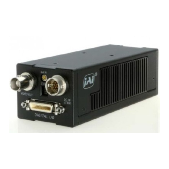
Page 4: Locations And Functions
CV-M2CL and CV-M8CL 4. Locations and Functions 1. CCD sensor 2. Lens mount (C-mount) *) 3. Rear panel with SW1 4. Digital output connector (Camera Link) 5. DC in/Trigger in/RS-232C connector 6. BNC connector for monitor video output 7. Gain potentiometer 8. -
Page 5: Pin Assignment
CV-M2CL and CV-M8CL 5. Pin Assignment 5.1. 12-pin Multi-connector (DC-IN/Trigger) Type: HR10A-10R-12PB-01 Pin no. Signal Remarks (Hirose) male. (Seen from rear of camera.) +12 V DC input Iris Video output Analog video for lens iris control in continuous mode and RCT mode. *) RXD in RS 232C on 12 pin. -
Page 6: Input And Output Circuits
CV-M2CL and CV-M8CL 5.4. Input and Output Circuits 5.4.1. Monitor video output On the BNC connector an analog video signal with 0.7Vpp 0.7Vpp Video Video sync is found if OS=2. The signal can be used +0.4V +0.4V Output Output for focus and field of view adjustments. -
Page 7: Camera Link Interface
CV-M2CL and CV-M8CL 5.4.5. Camera Link interface The video output is Camera Link, where the 2 channels with 10 or 8 bit video are placed in a base configuration. The digital output signals follow the Camera Link standardized multiplexed signal output interface. The output driver is NS type DS90CR285, and the receiver is NS type DS90CR286. -
Page 8: Functions And Operations
CV-M2CL and CV-M8CL 6. Functions and Operations In the following the format and the abbreviations shown in “7.5. CV-M2/M8 command list” are used for function commands and parameters. 6.1. Basic functions The M2/M8 cameras are a progressive scan camera with 10 or 8 bit video output in single or dual channel Camera Link. -
Page 9: Reset Continuous Trigger Mode
CV-M2CL and CV-M8CL 6.1.3. Reset continuous trigger mode The RCT mode makes it possible to use a lens with video controlled iris for intelligent traffic surveillance applications. TR=2. The camera is running continuously, and the iris is controlled from the iris video output. When a trigger pulse is applied, the scanning is reset and restarted, the previous signal is dumped with a fast dump read out, and the new triggered exposure is started. -
Page 10: Digital Video Out Allocation
CV-M2CL and CV-M8CL 6.1.5. Digital video out allocation The set-up and the relations between the analog and digital video are shown below. Digital Digital [LSB] [LSB] video out video out White White 1023 1023 clip level clip level 100% 100%... -
Page 11: Sensor Layout And Timing
CV-M2CL and CV-M8CL 6.2. Sensor layout and timing 6.2.1. CCD sensor layout The CCD sensor layout with respect to pixels and lines as it is used in the timing and video read out is shown below. For CV-M8CL the effective full frame Bayer sequence starts with GRG. -
Page 12: Horizontal Timing Single Channel
CV-M2CL and CV-M8CL 6.2.3. Horizontal timing single channel OS=0. Normal mode, full frame. 1ck = 25 nsec 1 LVAL per i od 1916ck 1674ck 242ck LVAL FVAL Rai si ng Edge FVAL Fal l i ng Edge FVAL 52ck 1864ck... -
Page 13: Horizontal Timing Dual Channel
CV-M2CL and CV-M8CL 6.2.5. Horizontal timing dual channel OS=1. Normal mode, full frame. 1ck = 25 nsec 1 LVAL p e r i o d 1 0 9 2 c k 2 3 8 c k 8 5 4 c k... -
Page 14: Lval Synchronous Accumulation
CV-M2CL and CV-M8CL 6.2.7. LVAL synchronous accumulation With LS=0, the accumulation will start synchronously with LVAL. The trigger pulse should be longer than 2 LVAL intervals, and the accumulation will then start at the first LVAL after the trigger leading edge. The exposure start delay will be up to 1 line. (Single channel 47.9 µsec. -
Page 15: Lval A-Synchronous Accumulation
CV-M2CL and CV-M8CL 6.2.8. LVAL a-synchronous accumulation With LS=1, the accumulation will start after the trigger leading edge. The exposure start delay will be 151 clk. pulses after the trigger. It is 3.76 µsec. In EPS mode the exposure stops 0.5 L after the selected shutter time, (in number of LVAL). -
Page 16: Partial Scanning Vertical Timing
CV-M2CL and CV-M8CL 6.2.9. Partial scanning vertical timing Partial scanning has 3 pre-selected vertical centred areas 1/2, 1/4 and 1/8. SC=1 through SC=3. With SC=4, the start and the height of the partial scanned area can be programmed with 1 line interval. -
Page 17: Vertical Binning
Note! Vertical binning is not supported from revision D! Vertical binning is a function on CV-M2CL only. It will add the pixel value from 2 adjacent lines, and read it out as a single line. The sensitivity is then doubled, but the vertical resolution is reduced to ½. -
Page 18: Input/Output Of Timing Signals
See the full connector pin assignment for Camera Link in chapter 5.3 and 5.4.5 For complete documentation on the Camera Link standard, please contact your JAI distributor. EEN is also found as a TTL signal on pin #9 on the 12 pin Hirose. EEN is low during exposure. -
Page 19: Continuous Operation (Non Triggered)
CV-M2CL and CV-M8CL 6.4.1. Continuous Operation (Non triggered) Mode settings can be done with RS-232C. Trigger Mode Normal. TR=0. It is for applications where the camera is continuously running without external trigger. The shutter mode can be normal or programmable exposure. (SM=0, SM=1). The shutter will work in all 10 steps up to 1/14,000 second or with the programmable exposure in 1216 steps. -
Page 20: Edge Pre-Select Mode
CV-M2CL and CV-M8CL 6.4.2. Edge Pre-select Mode In EPS mode, the trigger leading edge will start an exposure at the first LVAL pulse if LS=0, (or immediately if LS=1), and it stops and the resulting image is read out after the pre-selected shutter time. -
Page 21: Reset Continuous Trigger Mode
CV-M2CL and CV-M8CL 6.4.3. Reset Continuous Trigger mode The RCT mode is in principle the same as normal continuous mode. The difference is that an external trigger pulse will immediately stop the video read out and reset and restart the vertical timing. -
Page 22: Pulse Width Control Mode
CV-M2CL and CV-M8CL 6.4.4. Pulse Width Control Mode In PWC mode, the trigger leading edge will start an exposure at the first LVAL pulse if LS=0 (or immediately if LS=1). It stops at the trailing edge of the trigger pulse, and the resulting video is read out. -
Page 23: Burst Trigger Mode
CV-M2CL and CV-M8CL 6.4.5. Burst Trigger mode With the burst trigger function, a single trigger pulse can start a sequence with five previous set pre-selected programmable exposures. The five shutter times can be set with BSH1 through BSH5. (Exposure 1H through 1216H.) The exposure is LVAL synchronous. Preset shutter (SM=0) can not be used. -
Page 24: Piv Mode
CV-M2CL and CV-M8CL 6.4.6. PIV mode PIV mode (Particle Image Velocimetry) can be used in applications where 2 images should be taken with a very short time interval. It can only be used with strobe flash as the only illumination. The first accumulation time is fixed at 4.68 µsec. After a delay >1.5 µsec. the second exposure period starts. -
Page 25: Other Functions
CV-M2CL and CV-M8CL 6.5. Other Functions The following functions are described under their short ASCII command name. BA: Output bit allocation With this function the number of bits in the Camera Link video output can be selected to 10 or 8. -
Page 26: Mode And Function Matrix
√ √ √ √ √ √ √ √ √ = ok *1. V binning for CV-M2CL only *2. If partial scan and V binning is set, binning has highest priority. Fig. 33. Matrix for mode and functions. - 25 -... -
Page 27: Request Functions
CV-M2CL and CV-M8CL 6.6. Request Functions The following commands are for identification and help. Fig. 29. shows some printout examples from a PC running terminal emulator software. (Hyper terminal). Status, version, camera ID, model name, user ID and the help list are shown. - Page 28 AU(Auto dual ch adjustment): 0=off, 1=ABA, 2=AWA LD(Load settings from EEPROM): 0=factory, 1=user UD=1234567 SA(Save settings into EEPROM): 1=user *** Firmware Version 1.14 ***** Copyright(c) 2003 JAI Corporation ***** Fig. 34. Terminal printout of status, ID and help. - 27 -...
-
Page 29: Configuring The Camera
CV-M2CL and CV-M8CL 7. Configuring the Camera 7.1. Mode setting SW1 on rear Switch SW 1.1 on the camera rear can be used to select digital or analog video out. SW1.1 has higher priority than RS-232C. SW1.2 is for termination of the trigger 1 input on pin #10 Hirose. -
Page 30: Rs-232C Control
Camera Link. The control mode can be selected by the internal switch RS- 232C/Camera Link. The camera can be set up from a PC running terminal emulator software, or using JAI´s camera control software. Below is the description of the ASCII based short command protocol. -
Page 31: Cv-M2/M8 Cl Command List
CV-M2CL and CV-M8CL 7.5. CV-M2/M8 CL command list Command Name Format Parameter Remarks A – General settings and useful commands Echo Back 0=Echo off 1=Echo on Off at power up EB=[Param.]<CR><LF> Camera Status request ST?<CR><LF> Actual setting Online Help request HP?<CR><LF>... -
Page 32: Camera Control Tool For Cv-M2/M8 Cl
CV-M2CL and CV-M8CL 7.6. Camera Control Tool for CV-M2/M8 CL From www.jai.com Camera Control Tool for Windows NT/2000/XP can be downloaded. The control tool contents a camera control program and tools for making your own program. For the integrator and experienced user, the Camera Control Toll is much more than a program with a window interface. -
Page 33: Camera Control Tool Interface
The about window contains a picture of the camera and information about the version of the program, Internet connection to JAI A/S and access to the help documents. The List box that contains the help documents will list all files, which have the extension .pdf and that are found in the program (default) folder C:\Program Files\JAI A-S\’Control Tool Name’... - Page 34 CV-M2CL and CV-M8CL RS-232 communication. 1. Select ’COM-ports’ from the ’CL Manufacturer/COM-ports’ list Box. 2. Select the communication port, where the serial cable is connected to the camera from the ’Serial Port’ list box or click the ‘Auto’ button to search for a camera on communication port 1 to 16.
- Page 35 CV-M2CL and CV-M8CL Synchronize program and camera. The Camera Control software has the ability to synchronize either the camera or the program. Click Synchronize camera to write all settings from the program to the camera or click the Synchronize program to load all settings from the camera to the program.
-
Page 36: Using The Camera Control Tool
3. It is possible to work with the Camera Control Tool when the camera is online and when the camera is offline. 4. The newer JAI cameras always start up with the last used user area (but for some old models it will start up with the last saved user area.) 5. -
Page 37: External Appearance And Dimensions
Wave lenght (nm) W a v e le n g th (n m ) W a v e le n g th (n m ) Fig. 40. Spectral sensitivity for CV-M2CL Fig. 41. Spectral sensitivity for CV-M8CL - 36 -... -
Page 38: Specification Table
CV-M2CL and CV-M8CL 9.2. Specification table Specifications CV-M2CL CV-M8CL Scanning system Progressive 1216 lines 17 frames/sec. Pixel clock 40.00 MHz Line frequency, single output 20.88 kHz (1916 pixel clock/line). (H = 47.9 µsec) dual output 36.63 kHz (1092 pixel clock/line). (H = 27.3 µsec) -
Page 39: Appendix
2. Datasheet for CV-M2CL and CV-M8CL can be downloaded from www.jai.com 3. Camera control software for CV-M2CL and CV-M8CL can be downloaded from www.jai.com 4. Data for the CCD sensor Kodak KAI-2020M and 2020CM can be found on www.jai.com - 38 -... -
Page 40: Users Record
Company and product names mentioned in this manual are trademarks or registered trademarks of their respective owners. JAI A-S cannot be held responsible for any technical or typographical errors and reserves the right to make changes to products and documentation without prior notification.
Need help?
Do you have a question about the CV-M2CL and is the answer not in the manual?
Questions and answers