
Related Manuals for JAI SW-2001Q-CL


Summary of Contents for JAI SW-2001Q-CL
- Page 1 User's Manual SW-2001Q-CL RGB Color & NIR 4CCD Line Scan Camera Document Version:1.2 SW-2001Q-CL_Ver.1.2_Oct2021...
- Page 2 JAI Ltd., Japan and may only be used by the purchasers of the product. JAI Ltd., Japan makes no warranty for the use of its product and assumes no responsibility for any errors which may appear or for damages resulting from the use of the information contained herein.
- Page 3 Supplement The following statement is related to the regulation on “ Measures for the Administration of the control of Pollution by Electronic Information Products “ , known as “ China RoHS “. The table shows contained Hazardous Substances in this camera. mark shows that the environment-friendly use period of contained Hazardous Substances is 15 years.
-
Page 4: Table Of Contents
SW-2001Q-CL - Table of contents – General ....................... 5 Camera nomenclature ..................5 Main features ....................5 Locations and functions ..................6 4.1. Locations and functions ................6 4.2. Rear Panel ....................7 Connectors and pin assignment ................8 5.1. - Page 5 Serial communication and command list .............. 33 8.1. Serial communication ................33 8.2. Command list ..................34 Camera Control Tool for SW-2001Q-CL ..............39 External appearance and Dimensions ..............43 Specifications ................... 44 11.1 Typical data ..................... 44 11.2 Camera Spectral sensitivity ................ 46 Appendix ......................
-
Page 6: General
SW-2001Q-CL General The SW-2001Q-CL is a 4CCD line scan camera using four 2048 pixel line sensors mounted on a prism, for the R, G,B and NIR channels. It operates with a 40 MHz pixel clock, resulting in a maximum line rate of 19,048 lines per second. -
Page 7: Locations And Functions
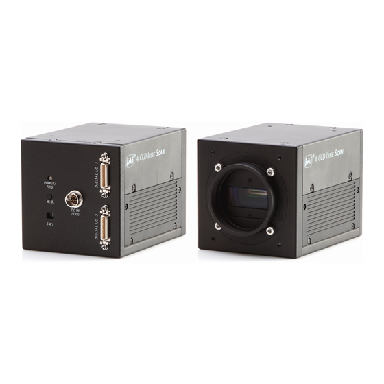
SW-2001Q-CL Locations and functions 4.1. Locations and functions ⑧ ② ⑦ POWER/ TRIG ⑥ W.B. DC IN /TRIG S W1 ① ⑤ ④ ③ ⑧ Fig. 1 Location of external features 1 Lens mount M52 mount (*1)Note) 2 Camera Link part 1... -
Page 8: Rear Panel
SW-2001Q-CL 4.2. Rear Panel ① POW ER / TRIG W . B . D C IN ② /TRIG S W 1 Fig2. Rear panel ① LED Green (Steady) Operating, but not receiving external trigger input Green (Flashing) Operating and receiving external trigger input. -
Page 9: Connectors And Pin Assignment
Cables, transmission systems and frame grabbers/acquisition boards that do not comply with the Camera Link standard may work with this camera, but JAI Camera Solutions cannot be held responsible for loss in performance or damage of equipment, including the camera. -
Page 10: Input And Output Circuits
SW-2001Q-CL Connector 2 ( Used only for 4 x 10 Bit output) Pin No In/Out Name Note 1,14 Shield 2(-),15(+) TxOUT0 3(-),16(+) TxOUT1 Data out 4(-),17(+) TxOUT2 5(-),18(+) TxClk Clock for CL 6(-),19(+) TxOUT3 Data out 7(+),20(-) 8(-),21(+) 9(-),22(+) 10( ),23(+) -
Page 11: Camera Link Interface (Bit Allocation)
SW-2001Q-CL 5.3.3 Camera Link Interface (Bit allocation) The SW-2001Q-CL follows the Camera Link standard in all respects. Port/Signal 8bitx4 output 10bitx4 output Connector Pin Name Port A0 Out1_D0 Out1_D0 Port A1 Out1_D1 Out1_D1 Port A2 Out1_D2 Out1_D2 Port A3 Out1_D3... -
Page 12: Camera Link Output Port
Tx25 DVAL Tx26 Tx23 5.3.4 Camera link output port SW-2001Q-CL handles R,G,B and NIR channels. The output ports for 8-bit and 10-bit are different. 8 bit output Input signal Camera link output Out1 Camera Link 1 Port a – c... -
Page 13: Functions And Operation
(the inverse of line rate). This also allows a fixed exposure time, independent of the line rate. In the SW-2001Q-CL the exposure time can be set individually for all four channels. -
Page 14: Operating Mode
SW-2001Q-CL 6.2. Operating mode The SW-2001Q-CL has three operating modes. They are No-Shutter mode, Shutter-Select mode and PWC (Pulse Width Control) mode. The following chapters explain the details of these three modes. The output detail is shown below and is common with all modes. -
Page 15: Shutter Mode With Internal Trigger
SW-2001Q-CL 6.2.1 No-Shutter mode with internal trigger In this mode the camera does not accept an external trigger signal, as the line rate is generated from an internal clock (user programmable, command LR). The exposure time is directly proportional to the line rate (T = 1/line rate). -
Page 16: Shutter Mode With External Trigger
SW-2001Q-CL 6.2.2 No-Shutter mode with external trigger In this mode, the exposure time is directly proportional to the line rate. The line rate is generated externally by a trigger signal. This mode is used when an external trigger signal is available, e.g. -
Page 17: Shutter-Select Mode With Internal Trigger
SW-2001Q-CL 6.2.3 Shutter-Select mode with internal trigger This mode allows the user to have full control of the line rate and the exposure time individually, by programming separate timing generators. Subsequently, the camera does not accept an external trigger signal in this mode. -
Page 18: Shutter-Select Mode With External Trigger
SW-2001Q-CL 6.2.4 Shutter-Select mode with external trigger This mode allows the user to have full control of the exposure time, by programming a timing generator, while the line rate is controlled by an external trigger signal. The camera can accept an external trigger through the Camera Link connector or though the 12-pin Hirose connector. -
Page 19: Pulse Width Control (Pwc) Mode
SW-2001Q-CL 6.2.5 Pulse Width Control (PWC) mode In this mode, the user has full control of both the line rate and the exposure time of each line via the External Trigger input. At the falling edge of the External Trigger signal, the exposure is initiated, and at the rising edge the exposure is terminated and read out. -
Page 20: Scan Rate And Exposure Time Range
SW-2001Q-CL 6.3. Scan rate and exposure time range 6.3.1 Minimum cycle time of external trigger Mode Minimum trigger cycle No-Shutter C1+52.5μs Shutter-Select C1+53.75μs Exposure + C2 C1 =0.1μs; C2= 54.2μs 6.3.2 Minimum trigger pulse width. Mode Via Camera Link Via Hirose 12-pin... -
Page 21: Functions Listed Alphabetically By Command Acronyms
Settings 0 (off) and 1 (on). Factory default is 0 (off). In this mode, when a trigger pulse does not occur after more than 53ms, the SW-2001Q-CL automatically returns to continuous operation with the line rate of 52.5μs. In this time, the camera operates by the internal trigger, and if the trigger is input, the video is immediately output. -
Page 22: Command Ah - Activate One-Push Auto White Balance (Awb) - Shutter
SW-2001Q-CL Command AH - Activate One-Push Auto White Balance (AWB) - Shutter By sending this command via the serial communication, the shutter based One-Push AWB function is activated. The white balance function takes approximately 3 seconds to complete. During this time the rear panel LED will show orange. -
Page 23: Command Bi - Binning (Horizontal Only)
0 LSB to 64 (16) LSB. The number in parenthesis is valid for 32-bit output. The SW-2001Q-CL has an automatic black level clamp function. This circuit is an analog circuit and after the signal level of dummy pixels is clamped at the constant level, it is digitized and the OB level is clamped at 32 LSB (8 LSB) in the digital clamp circuit. -
Page 24: Command Ei - Interlocked R, G, B & Nir Exposure
SW-2001Q-CL 7.12 Command EI – Interlocked R, G, B & NIR Exposure When this function enabled (interlocked), exposure time for all four channels is selected by setting the green channel and the red, blue and NIR channels will track. To obtain white balance, adjust red and blue channels, PER and PEB. It is thereafter possible to adjust overall exposure time by using the command PEG. -
Page 25: Commands Gar2 , Gag2, Gab2 And Gair2 - Fine Gain (R,G, B And Nir)
• It is recommended to use 52.5μs to 2ms of line rate because the black level is stable in this range. 7.18 Command LUTC - LUT Control The SW-2001Q-CL has an internal LUT(Look Up Table) for setting gamma. Command LUTC selects gamma OFF, Gamma 0.45 or LUT. Settings: 0 = Off 1 = 0.45... -
Page 26: Command Nr - Noise Reduction
SW-2001Q-CL Fig.18 LUT characteristics γ=User In this mode, R,G,B or NIR can be set individually. Settings: Range: 0 to 8191 LSB (200%) Setting point: 512 Setting point 7.19. Command NR - Noise Reduction Noise levels less than 16 LSB (4LSB) which are superimposed on the video signal will be eliminated. -
Page 27: Command Pbs - Request Status After Pixel Black Correction
SW-2001Q-CL exposure time and line rate at which the camera will be operated. Principle of Pixel black level correction (DSNU / FPN correction) Dark Signal Non-Uniformity or Fixed Pattern Noise is, as the name implies, fixed pattern on the sensor output, which is not dependent on the incoming light. -
Page 28: Command Pgr - Pixel Gain Correction And Store In User Area
SW-2001Q-CL compensates for Pixel Response Non Uniformity (PRNU) for individual pixels. The algorithm for compensation is different in No-Shutter mode and Shutter-Select mode. If the operating mode is changed, an adjustment in the selected mode must be made. The factory default is Shutter-Select mode. -
Page 29: Command Pgs - Request Status After Pixel Gain Correction
SW-2001Q-CL recommend level is half of maximum), and the average across the line is calculated. Based on this average, coefficients are then generated for each individual pixel. The coefficient has the function of multiplying the pixel output with a factor greater or less than 1. These coefficients are stored in a non-volatile memory, and are therefore maintained after power down. -
Page 30: Command Sds - Request Status After Executing Shading Correction Command
SW-2001Q-CL optics and/or illumination used together with the camera, it may not be possible to fully compensate for shading. Operating procedure for individual R, G ,B and NIR channel shading correction: 1. Before making adjustment, approximately 30 minutes of warm up is required. -
Page 31: Command Tg - Trigger Origin
SW-2001Q-CL 7.30. Command TG – Trigger Origin Selects whether an external signal or an internal clock generator is used as a trigger source. Settings: 0=Internal clock generator 1=External signal Associated commands: 7.31. Command TI – Trigger Input Selects whether the External Trigger input signal is taken from the Camera Link connector, or from the 12-pin Hirose connector. -
Page 32: Command Ts - Test Pattern
SW-2001Q-CL 7.34. Command TS – Test Pattern This allows the camera to output a number of test patterns for set-up and troubleshooting. Settings: 0=off 1=Color bar 2=Gray wedge 3=Gray bars 4=White (890LSB) Signal 32 (8) 10bit (8-bit) Pixel count 2048 Fig. -
Page 33: Command Wb - White Balance
SW-2001Q-CL 890 (222) 10bit (8-bit) Signal (RGB) 32 (8) 10bit (8-bit) Pixel count 2048 Fig. 19 White level test pattern 7.35. Command WB – White Balance The white balance function can be used for manual setting, one-push automatic white balance (AWB) and fixed color temperatures (3 selections) -
Page 34: Serial Communication And Command List
8.1. Serial communication The SW-2001Q-CL can communicate by serial communication via the Camera Link connector or via RS232C in the 12-pin Hirose connector. The Baud Rate is fixed at 9600 bps. Switch SW1 at the rear panel of the camera is used to select which way the serial communication is set up. -
Page 35: Command List
SW-2001Q-CL Transmit the following to have a command list: HP?<CR><LF> The camera answers: A list with all commands and possible settings Invalid parameters send to camera: (99 is an invalid parameter) SH=99<CR><LF> The camera answers: 02 Bad Parameters!!<CR><LF> To see firmware number. - Page 36 SW-2001Q-CL Auto line rate AL=[Param.]<CR><LF> reference 0 to 1023 Only valid for TG=0 AL?<CR><LF> level RB Exposure EI=[Param.]<CR><LF> 0=Off (independent) interlocked Only valid for TR=1 EI?<CR><LF> 1=On (interlocked) with G PER=[Param.]<CR><LF Programmable 80 to 2150400, in 25ns > Only valid for TR=1...
- Page 37 SW-2001Q-CL 0=Off 1=Color Bar TS=[Param.]<CR><LF> Test Pattern 2=Gray Pattern 1 Off at power up TS?<CR><LF> 3=Gray Pattern 2 4=White E - Gain, white balance and signal settings Gain Level - GA=[Param.]<CR><LF> Master Tracking:-132 to 429 0=0dB Master GA?<CR><LF> Individual:-363 to 660 Gain Level - GAR=[Param.]<CR><LF>...
- Page 38 SW-2001Q-CL 6554/8192(1.2) 8192=1 GAIR2=[Param.]<CR><LF> GAIR2 Fine gain - NIR 6544 to 9830 6554/8192(0.8) GAIR2?<CR><LF> 6554/8192(1.2) Noise NR=[Param.]<CR><LF> 0 = OFF, 1= ON reduction LUTC=[Param.]<CR><LF> LUTC LUT Control 0 = OFF, 1= 0.45, 2=User LUTC?<CR><LF> LUTR=[Param.]<CR><LF> Data:512 LUTR LUT data - Red LUTR?<CR><LF>...
- Page 39 SW-2001Q-CL correction 2=User area mode Run pixel black 0=Run pixel black PBR=[Param.]<CR><LF> correction, correction, store to user Store in user setting. PBR?<CR><LF> store to user area area 0=Pixel black correction has Inquire the not been finished yet. status after PBS?<CR><LF>...
-
Page 40: Camera Control Tool For Sw-2001Q-Cl
Connect the camera to the PC on which the software is installed and set the power ON. Then select “All programs” in the Windows start menu, select “JAI A-S” and click “SW-2001Q-CL control tool”. SW-2001Q-CL Camera Control Tool and Communication windows will open. - Page 41 SW-2001Q-CL 9.4. Camera control window When the connection between camera and PC is completed, the camera control tool shows the current camera settings. 9.5. LUT setting Open the drop-down menu under “LUT” and click “User”. When you click “LUT setting”, the following four windows for NIR, Red, Blue and Green will be...
- Page 42 SW-2001Q-CL When you drag the line and move it, the required gamma characteristics can be obtained. 9.6. Menus 9.6.1 File menu Open: Transfer the setting parameters in HDD or other memory devices to the camera. The extension is .cam Save as: Store the setting parameters in HDD other memory devices.
- Page 43 SW-2001Q-CL 9.5.4 Gamma menu Open Data file: Transfer the LUT data stored in HDD or the other memory devices, to the Control software. The file extension is .csv. Save Data to File: Store the LUT data set in the Control software, to HDD or other memory devices.
-
Page 44: External Appearance And Dimensions
SW-2001Q-CL External appearance and Dimensions 4-M4 Depth 6 Camera Link connector Port 1 U4-40: Fixed screw POWER / TRIG W.B. DC IN / TRIG M52 mount HIROSE 12pin connector 4-M4 Depth 6 Camera Link connector Port 2 4-M4 Depth 6 Outside size tolerance: ±... -
Page 45: Typical Data
SW-2001Q-CL Specifications 11.1 Typical data Scanning system Line Scan Effective pixels : 2048 pixels Image Sensor Pixel Size : 14.0μm × 14.0μm Effective image length : 28.672mm Pixel clock 40.00 MHz No-Shutter mode Line rate: 52.5 μs (with internal trigger) - Page 46 SW-2001Q-CL Shutter-select internal trigger modes. Available for Shutter-Select mode Electronic shutter Adjustable range : 2μs clk) to 53.76ms (Note 1) Adjustment increments : 25ns (1 clk) Binning Horizontal Test pattern 0: Color Bar 1: Gray 1 2: Gray 2 3: White (890 LSB) 1.
-
Page 47: Camera Spectral Sensitivity
SW-2001Q-CL CE (EN61000-6-2+EN61000-6-3) IEC61000-4-2 Conforming to Level 4 (Note 3) Regulation FCC Part15 Class B RoHS WEEE 90(W) x 90(H) x 120(D) mm (without connector and lens mount Dimensions protrusion) Weight 1050 g Camera Link : 10226-1A10JL x2 Connectors 12-Pin : HIROSE(HR10A-10R-12PB) or permissible substitute... -
Page 48: Appendix
SW-2001Q-CL Appendix Precautions Personnel not trained in dealing with similar electronic devices should not service this camera. The camera contains components sensitive to electrostatic discharge. The handling of these devices should follow the requirements of electrostatic sensitive components. Do not attempt to disassemble this camera. -
Page 49: Caution When Mounting The Camera
Refer to the technical note “Storing Data in On-Camera Flash Memory” for more information. Note: JAI strongly recommends saving images to the PC or other storage location because the non- volatile flash memory may not have enough memory size to store large data. -
Page 50: Change History
SW-2001Q-CL Change history Date Revision Changes Apr 2017 New release Dec 2020 China RoHS Oct 2020 Added the Non-Volatile Flash Memory information. -
Page 51: User's Record
Company and product names mentioned in this manual are trademarks or registered trademarks of their respective owners. JAI A-S cannot be held responsible for any technical or typographical errors and reserves the right to make changes to products and documentation without prior notification.
Need help?
Do you have a question about the SW-2001Q-CL and is the answer not in the manual?
Questions and answers