
Related Manuals for Billion BiPAC 7700N


Summary of Contents for Billion BiPAC 7700N
-
Page 1: User Manual
BiPAC 7700N 802.11n ADSL2+ Firewall Router User Manual Version released: B038_K82_GH-00-1659 Last revised date: 01-19-2011... -
Page 2: Table Of Contents
Table of Contents Chapter 1: Introduction ........................1 Introduction to your Router ...................... 1 Features ..........................3 ADSL Compliance...................................3 Network Protocols and Features............................3 Firewall......................................4 Quality of Service Control................................4 ATM and PPP Protocols ................................4 IPTV Applications ...................................4 Wireless LAN.....................................4 Management.....................................5 Hardware Specifications......................6 Physical Interface..................................6 Chapter 2: Installing the Router ..................... - Page 3 DMZ Host........................77 Security......................................78 IP Filtering.........................78 Outgoing ......................78 Incomig .......................80 MAC Filtering ......................82 Parental Control..................................83 Time Restriction ......................83 Url Filter......................................85 QoS - Quality of Service................................87 Queue Config......................89 QoS Classification.....................92 Routing....................................100 Default Gateway .....................100 Static Route ......................101 Policy Routing ......................102 RIP ..........................103 DNS......................................104 Dynamic DNS ......................105 DSL......................................106...
-
Page 4: Chapter 1: Introduction
IPTV, VOD, or online gaming without consuming bandwidth. High-speed Internet Access The BiPAC 7700N is compliant with worldwide ADSL standards, and supports download rates of up to 12 / 24Mbps using ADSL2 / 2+, 8Mbps using ADSL and an upload rate of up to 1Mbps. The integrated Annex M standard supports ADSL2 / 2+ for higher uploads by doubling the upload data rate. - Page 5 VPI/VCI 8/35, you can set the PPPoE, IPoE, and Bridge connection via the PVC without respectively assigning the three services to three different PVCs. Virtual AP A “Virtual Access Point” is a logical entity that exists within a physical Access Point (AP). When a single physical AP supports multiple “Virtual APs”, each Virtual AP appears to stations (STAs) to be an independent physical AP, even though only a single physical AP is present.
-
Page 6: Features
Features • Supports Multiple LAN segment for multiple network application • 4-port 10 / 100Mbps Ethernet switch integrated • High-speed Internet Access via ADSL2 / 2+; Backward Compatible with ADSL • 802.11n Wireless Access Point with Wi-Fi Protected Setup (WPS), Wi-Fi Protected Access (WPA-PSK/ WPA2-PSK) and Wired Equivalent Privacy (WEP) support •... -
Page 7: Firewall
Firewall • Built-in NAT Firewall • Stateful Packet Inspection (SPI) • Prevents DoS attacks including Land Attack, Ping of Death, etc. • Remote access control for web base access • Packet Filtering - port, source IP address, destination IP address, MAC address •... -
Page 8: Management
• WDS repeater function support • 802.1x radius supported • Web-based GUI and hardware push button for WLAN on/off switch control Management • Web-based GUI for remote and local management • Firmware upgrades and configuration data upload and download via web-based GUI •... -
Page 9: Hardware Specifications
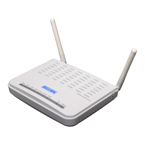
Hardware Specifications Physical Interface • WLAN: 2 x 2dbi antennas • DSL: ADSL port • Ethernet: 4-port 10 / 100Mbps auto-crossover (MDI / MDI-X) Switch • Factory default reset button • WPS push button • WLAN On/Off push button • Power jack •... -
Page 10: Chapter 2: Installing The Router
Chapter 2: Installing the Router Package Contents • BiPAC 7700N Wireless-N ADSL2+ Firewall Router • CD containing the on-line manual and setup wizard utility • RJ-11 ADSL/ telephone cable • Ethernet (RJ-45) cable • Power adapter • Quick Start Guide... -
Page 11: Important Note For Using This Router
Important note for using this router... -
Page 12: Device Description
Device Description The Front LEDs Meaning Lit red when WAN port fails to get IP address. Lit green when WAN port gets IP address successfully. Internet Unlit when the device is in bridge mode or WAN connection is absent. Lit green when the device is successfully connected to an ADSL DSLAM. -
Page 13: The Rear Ports
The Rear Ports Port Meaning Wireless antennas. Wireless Antenna Connect it with the supplied power adapter. Power Power ON/OFF switch. Switch Push WPS button to trigger Wi-Fi Protected Setup function. For WPS configuration detail, please refer to Setup section of this User Manual. Press to enable wireless when wireless is disabled and the WLAN LED lit. -
Page 14: Cabling
Cabling One of the most common causes of problems is bad cabling or ADSL line(s). Make sure that all connected devices are turned on. In the front panel of your router is a bank of LEDs. Verify that the LAN Link and ADSL line LEDs are lit. If they are not, verify if you are using the proper cables. If the error persists, you may have a hardware problem. -
Page 15: Chapter 3: Basic Installation
Chapter 3: Basic Installation The router can be configured through your web browser. A web browser is included as a standard application in the following operating systems: Linux, Mac OS, Windows 7 / 98 / NT / 2000 / XP / Me / Vista, etc. -
Page 16: Connecting Your Router
Connecting Your Router Users can connect the ADSL2+ router as follows. -
Page 17: Network Configuration
Network Configuration Configuring PC in windows 7 Go to Start. Click on Control Panel. Then click on Network and Internet. 2. When the Network and Sharing Center window pops up, select and click on Change adapter settings on the left window panel. - Page 18 4. Select Internet Protocol Version 4 (TCP/IPv4) then click Properties. 5. In the TCP/IPv4 properties window, select the Obtain an IP address automatically and Obtain DNS Server address automatically radio buttons. Then click OK to exit the setting. 6. Click OK again in the Local Area Connection Properties window to apply the new configuration.
-
Page 19: Configuring Pc In Windows Vista
Configuring PC in Windows Vista 1. Go to Start. Click on Network. 2. Then click on Network and Sharing Center at the top bar. 3. When the Network and Sharing Center window pops up, select and click on Manage network connections on the left window column. - Page 20 5. Select Internet Protocol Version 4 (TCP/IPv4) then click Properties. 6. In the TCP/IPv4 properties window, select the Obtain an IP address automatically and Obtain DNS Server address automatically radio buttons. Then click OK to exit the setting. 7. Click OK again in the Local Area Connection Properties window to apply the new configuration.
-
Page 21: Configuring Pc In Windows Xp
Configuring PC in Windows XP Go to Start > Control Panel (in Classic View). In the Control Panel, double-click on Network Connections 2. Double-click Local Area Connection. In the Local Area Connection Status window, click Properties. Select Internet Protocol (TCP/IP) and click Properties. -
Page 22: Configuring Pc In Windows 2000
Configuring PC in Windows 2000 1. Go to Start > Settings > Control Panel. In the Control Panel, double-click on Network and Dial-up Connections. 2. Double-click Local Area Connection. In the Local Area Connection Status window click Properties. Select Internet Protocol (TCP/IP) and click Properties. -
Page 23: Configuring Pc In Windows 95/98/Me
Configuring PC in Windows 95/98/Me 1. Go to Start > Settings > Control Panel. Control Panel, double-click Network and choose the Configuration tab. 2. Select TCP/IP > NE2000 Compatible, or the name of your Network Interface Card (NIC) in your PC. Select Obtain address... -
Page 24: Configuring Pc In Windows Nt4.0
Configuring PC in Windows NT4.0 1. Go to Start > Settings > Control Panel. In the Control Panel, double-click on Network and choose the Protocols tab. 2. Select TCP/IP Protocol and click Properties. 3. Select the Obtain an IP address from a DHCP server radio button and click OK. -
Page 25: Factory Default Settings
Factory Default Settings Before configuring your router, you need to know the following default settings. Web Interface (Username and Password) Three user accounts are provided by this router, admin, support and user respectively. See Access Control. Admin: the one who has unrestricted access to change and view configuration of your Broadband Router. - Page 26 LAN and WAN Port Addresses The parameters of LAN and WAN ports are pre-set in the factory. The default values are shown in the table. IPv4 LAN Port WAN Port IPv4 address 192.168.1.254 Subnet Mask 255.255.255.0 The PPPoE function is enabled to automatically get DHCP server function Enabled...
-
Page 27: Information From Your Isp
Information from your ISP Before configuring this device, you have to check with your ISP (Internet Service Provider) to find out what kind of service is provided such as DHCP (Obtain an IP Address Automatically, Static IP (Fixed IP Address) or PPPoE. Gather the information as illustrated in the following table and keep it for reference. -
Page 28: Configuration Via Web Interface
Configuration via Web Interface Open your web browser; enter the IP address of your router, which by default is 192.168.1.254, and click or press ‘Enter’ key on the keyboard, a login prompt window will appear. The default root username and password are “admin” and “admin” respectively. Congratulations! You are now successfully logged in to the Firewall Router! After logging in to the router you will see Quick Start Wizard as shown below, please follow the steps on following pages to configure your device. -
Page 29: Quick Start
Quick Start This part is to let you quickly configure and start your router to access internet. 1. Select DSL, press Continue to go on to next step, or if you only want to configure Wireless, press Jump to Wireless setting to go to step 8. Click Quick Setup to give up and return to the Device Info page. - Page 30 4. Here you should select the Layer2 Interface, ATM. Click Add to add WAN Interface. 5. According to your ISP, type the VPI/VCI, select appropriate Link type and the Encapsulation mode. Click Continue to go to next step. 6. Enter the username, password from your ISP, for IP and DNS settings, also refer to your ISP. Click Continue to go on.
- Page 31 7. WAN port configuration has been finished. 8. After the configuration is successful, click Next to Wireless button and you may proceed to configure the Wireless setting. For security information, please turn to wireless>security section in this manual for help. Click Continue. 9.
- Page 32 You’ve now configured your router and can now access the internet, turn to Device Info, you will see basic information”. For more information, turn to Advanced setup for help. ...
-
Page 33: Chapter 4: Configuration
Chapter 4: Configuration Once you have logged on to your BiPAC 7700N Router via your web browser, you can begin to set it up according to your requirements. On the configuration homepage, the left navigation pane links you directly to the setup pages, which include:... -
Page 34: Device Info
Device Info This Section gives users an easy access to the information about the working router and view the current status of the router. Here Summary, WAN, Statistics, Router, ARP and DHCP six subsections are included. -
Page 35: Summary
Summary The basic information about the device is provided here (the following is a configured screenshots to let users understand clearly). Device Information Model Name: Display the model name. Software Version: Firmware version. DSL PHY and Driver Version: Display DSL PHY and Driver version. Wireless Driver Version: Display wireless driver version. -
Page 36: Wan
This table displays the information of the WAN connections, users can turn here for WAN connection information. Interface: the WAN connection interface. Description: the description of this connection. Type: the protocol used by this connection. VlanMuxld: Show the status of the VLANMuxld, VLAN ID or disabled. If VLAN ID is -1, then disabled is shown in this field, while if VLAN ID isn’t -1, the exact VLAN ID is shown here in this field. -
Page 37: Statistics
Statistics The table shows the statistics of LAN. Interface: List each LAN interface. LAN1-LAN4 indicate the four LAN interfaces. Bytes: Display the Received and Transmitted traffic statistics in Bytes. Pkts: Display the Received and Transmitted traffic statistics in Packets. Errs: Display the statistics of errors arising in Receiving or Transmitting data. Drops: Display the statistics of drops arising in Receiving or Transmitting data. -
Page 38: Xtm
The Statistics-xTM screen displays all the xTM statistics Port Number: Shows number of the port for xTM. In Octets: Number of received octets over the interface. Out Octets: Number of transmitted octets over the interface. In Packets: Number of received packets over the interface. Out Packets: Number of transmitted packets over the interface. -
Page 39: Xdsl
xDSL Mode: Modulation protocol, including G.dmt, G.lite, T1.413, ADSL2, AnnexL, ADSL2+ and AnnexM. Traffic Type: transfer mode,ATM. Status: Show the status of DSL link. Link Power State: Show link output power state. Line Coding (Trellis): Trellis on/off. SNR Margin (0.1 dB): show the Signal to Noise Ratio(SNR) margin. Attenuation (0.1 dB): This is estimate of average loop attenuation of signal. - Page 40 Output Power (0.1 dBm): show the output power. Attainable Rate (Kbps) : The sync rate you would obtain. Rate (Kbps): show the downstream and upstream rate in Kbps. Super Frames: the total number of super frames. Super Frame Errors: the total number of super frame errors. RS Words: Total number of Reed-Solomon code errors.
- Page 41 Reset : Click this button to reset the statistics.
-
Page 42: Route
Route Destination: the IP address of destination network. Gateway: the IP address of the gateway this route uses. Subnet Mask: the destination subnet mask. Flag: show the status of the route. U: show the route is activated or enabled. H (host): destination is host not the subnet. G: show that the outside gateway is needed to forward packets in this route. -
Page 43: Arp
This section displays the router’s ARP (Address Resolution Protocol) Table, which shows the mapping of Internet (IP) addresses to Ethernet (MAC) addresses. This is useful as a quick way of determining the MAC address of the network interface of your PCs to use with the router’s Firewall – MAC Address Filter function. -
Page 44: Dhcp
DHCP The DHCP Table lists the DHCP lease information for all IP addresses assigned by the DHCP server in the device. Host Name: The Host Name of DHCP client. MAC Address: The MAC Address of internal DHCP client host. IP Address: The IP address which is assigned to the host with this MAC address. Expires In: Show the remaining time information during registration. -
Page 45: Advanced Setup
Advanced setup When you click this item, the column will expand to display the sub-items that will allow you to further configure your router. Layer2 Interface, Service, LAN, NAT, Security, Parental Control, Filter, Quality of Service, Routing, DNS, DSL, UPnP, Proxy, Interface Grouping and Multicast. -
Page 46: Layer2 Interface
Layer2 Interface A WAN (Wide Area Network) is a computer network that covers a broad geographical area (eg. Internet) that is used to connect LAN and other types of network systems. ATM Interface The following is the interface listing table. Click Add to add WAN interface. - Page 47 Select DSL Link Type: select the link type (protocol), EOA, PPPoA, IPoA. Select Connection Mode: Default Mode: this mode only allows single service over one connection. VLAN MUX Mode: this mode allows multiple services over one PVC. The two modes can be different in WAN service configuration. And PPPoA and IPoA do not use Ethernet frames for data transfer so they cannot work with VLAN Mux feature.
- Page 48 UBR with PCR/ CBR(Constant Bit Rate) UBR is a kind of service providing constant rate service, is idea for timely and fixed bandwidth needed service. Peak Cell Rate: enter Peak Cell Rate. Non Realtime VBR/ Realtime VBR(Variable Bit Rate) VBR is a kind of service providing some assurance about latency and bit loss rate and is often associated with video and time sensitive service.
- Page 49 Now follow the above steps, we set two ATM WAN interfaces for future illustration, one is of DefaultMode, and one is of VlanMuxMode.
-
Page 50: Wan Service
WAN Service WAN Service allows you to configure one or more services over one interface (connection). The following is the WAN Service listing table. Your configured WAN service will be listed here. Default Connection mode Select the interface which is a Default mode connection configured in WAN Service, here for example, in the following, atm0/(0_8_35) is a Default mode connection. - Page 51 PPPoE Select WAN service type: select the protocol advised by your ISP, here select PPPoE. Enter Service Description: user-defined description. Click Next to go on.
- Page 52 PPP Username: enter ISP account. PPP Password: enter the password. PPPoE Service name: user-defined name. Authentication method: select the authentication method. Enable Fullcone NAT: enable or disable fullcone NAT. Fullcone is a kind of NAT, in this mode, all requests from the same internal IP address and port are mapped to the same external IP address...
- Page 53 and port. Furthermore, any external host can send a packet to the internal host, by sending a packet to the mapped external address. Note: In PPPoE connection, NAT is enabled by default, you can determine whether to enable Fullcone NAT. And while you disabled Fullcone NAT and only use NAT, the default NAT type is Port Restricted cone NAT.
- Page 54 Click Next to go on to set DNS Server.
- Page 55 Select the DNS Server or enter the one yourself. Click Next to go on. Then you can view the information about your settings.
- Page 56 If you confirm about the above settings, click Apply/Save to apply your settings. Then the service will be listed as follows. If you don not need the service, select the item you want to remove, check the checkbox, then press Remove, it will be OK.
- Page 57 IP over Ethernet Select WAN service type: select the protocol advised by your ISP, here select IP over Ethernet. Enter Service Description: user-defined description. Click Next to go to next step.
- Page 58 Here two modes are supported for users to deal with the IP and DNS. You can select obtain automatically or manually input the information according to your ISP. Obtain an IP address automatically: check whether to enable this function. Option 60 Vendor ID: Enter the associated information by your ISP. This option is used by DHCP clients to optionally identify the vendor type and configuration of a DHCP client.
- Page 59 Enable NAT: The NAT (Network Address Translation) feature allows multiple users to access the Internet through a single IP account by sharing the single IP address. If users on your LAN have their own public IP addresses to access the Internet, NAT function can be disabled. When enabled, a Fullcone NAT parameter will appear, you can determine whether to enable Fullcone NAT.
- Page 60 Click Next to go on to set DNS.
- Page 61 Select DNS server interface from available WAN interfaces, or you can set the one yourself by select Use the following Static DNS IP address and enter the appropriate ones. Click Next to go on to check the settings. Click Apply/Save to apply your settings.
- Page 62 Bridging Select WAN service type: select the protocol advised by your ISP, here select Bridging. Enter Service Description: user-defined description. Click Next to go to next step. Click Apply/Save to apply your settings.
- Page 63 VLAN MUX Connection Mode It is similar to Default Connection in configuration. Select the interface which is a VLAN MUX mode connection configured in WAN Service, here for example, in the following, atm1/(0_1_35) is a VLAN MUX mode connection. select interface(VLAN MUX mode). Click Next to go on to next step.
- Page 64 be used to prioritize different classes of traffic (voice, video, data, etc). Enter the priority identification, tagged:0-7, untagged:-1. Enter 802.1Q VLAN ID: It is a parameter to specify the VLAN which the frame belongs. Enter the VLAN ID identification, tagged: 0-4094, untagged:-1. You can leave 802.1P Priority and 802.1Q VLAN ID as default setting,-1, means untagged, in this mode, the vlan tag header will not be contained, but if you want to allow one service for the specific vlan, here you should set the two parameters, the vlan tag header will be contained.
- Page 65 Click Next to set the default gateway of this connection. Click Next to set the DNS.
- Page 66 Click Next to view the information you have set to the connection, then click Apply/Save to save your settings.
- Page 67 Then you can see the PPPoE connection is listed below. Here it is just one service over atm1/(0_1_35). Then we can again set a Bridging connection over atm1/(0_1_35) interface. Click Add in the above page, the atm1/(0_1_35) also is listed for selection to add services. Continue clicking Next to select Bridging connection type.
- Page 68 Click Next to make sure your settings below match the settings provided by your ISP. And Click Apply/Save to save your settings.
- Page 69 The connections over one PVC as follows: This screen is the interface we set previous, here used for understanding. The below is WAN connection status, here you can see clearly the multiple services over one PVC. See from the above diagrams, we have set one PVC, it is VPI/VCI 1/35. But we have set two services on the same PVC, they are bridging and PPPoE services.
-
Page 70: Lan - Local Area Network
LAN - Local Area Network A Local Area Network (LAN) is a shared communication system network where many computers are connected. This type of network is area defined and is usually limited to a confined region within a building or just within the same storey of a building. Parameters Group Name: here group refers to the group you set in Interface Grouping section, you can set the parameters for the specific group. - Page 71 Subnet Mask: the default Subnet mask on the router. Enable IGMP Snooping: Enable or disable the IGMP Snooping function. Without IGMP snooping, multicast traffic is treated in the same manner as broadcast traffic - that is, it is forwarded to all ports.
- Page 72 End IP Address: the end IP address f the range the DHCP Server used to assign to the Clients. Leased Time: Set the leased time for each DHCP Client. Static IP List: The specified IP will be assigned to the corresponding MAC Address listed in the following table when DHCP Server assigns IP Addresses to Clients.
-
Page 73: Nat
NAT (Network Address Translation) feature translates a private IP to a public IP, allowing multiple users to access the Internet through a single IP account, sharing the single IP address. It is a natural firewall for the private network. Virtual Servers In TCP/IP and UDP networks a port is a 16-bit number used to identify which application program (usually a server) incoming connections should be delivered to. - Page 74 The following configuration page will appear to let you configure. Use Interface: select from the drop-down menu the interface you want the virtual server(s) applies Server Name: Select a Service: select the server name from the drop-down menu. Custom Service: it is a kind of service to let users customize the service they want. Enter the user-defined service name here.
- Page 75 access to internal network. End: Enter a port number as the external ending number for the range you want to give access to internal network. Internal Port Start: Enter a port number as the internal staring number. End: Here it will generate automatically according to the End port number of External port and can’t be modified.
- Page 76 2. Press Apply/Save to conform, and the items will be list as below. Remove If you don’t need a specified Server, you can remove it. Check the check box beside the item you want to remove, then press Remove, it will be OK.
-
Page 77: Port Triggering
Port Triggering Some applications require that specific ports in the Router's firewall be opened for access by the remote parties. Port Trigger dynamically opens up the 'Open Ports' in the firewall when an application on the LAN initiates a TCP/UDP connection to a remote party using the 'Triggering Ports'. The Router allows the remote party from the WAN side to establish new connections back to the application on the LAN side using the 'Open Ports'. - Page 78 Use Interface: select from the drop-down menu the interface you want rule applies to. Application Name: Select an application: select an existing application from the drop-down menu. Custom application: creating your own service. Trigger Port Start: type a number used as trigger port start number. Trigger dynamically opens up the 'Open Ports' in the firewall when an application on the LAN initiates a TCP/UDP connection to a remote party using the 'Triggering Ports'.
- Page 79 2. Press Save/Apply to summit your settings. If you want to delete the rule, please check the Remove checkbox first then press Remove button.
-
Page 80: Dmz Host
DMZ Host The DMZ Host is a local computer exposed to the Internet. When setting a particular internal IP address as the DMZ Host, all incoming packets will be checked by the Firewall and NAT algorithms then passed to the DMZ host, when a packet received does not use a port number used by any other Virtual Server entries. -
Page 81: Security
Security IP Filtering IP filtering enables you to configure your router to block specified internal/external users (IP address) from Internet access, or you can disable specific service requests (Port number) to /from Internet. The relationship among all filters is “or” operation, which means that the router checks these different filter rules one by one, starting from the first rule. - Page 82 Filter name: a user-defined filter name or you can select from the drop-down menu the application, and leave the automatically generated name as the Filter name. IP Version: IP Version,here IPv4. Protocol: Specify the packet type (TCP/UDP, TCP, UDP, ICMP) that the rule applies to. Source IP Address / Destination IP Address: This is the Address-Filter used to allow or block traffic to/from particular IP address (es).
-
Page 83: Incomig
Incomig In this Incoming IP filter, all incoming IP traffic is blocked when firewall is enabled on a WAN or LAN interface. But you can set up some rules to allow some IP traffic go through. You can change the default policy to change the default IP incoming policy. Click Add to add the new rules. - Page 84 Protocol: Specify the packet type (TCP/UDP, TCP, UDP, ICMP) that the rule applies to. Source IP Address / Destination IP Address: This is the Address-Filter used to allow or block traffic to/from particular IP address (es). Input the IP or IP/prefix ((such as single IP: 192.168.1.135/32.
-
Page 85: Mac Filtering
MAC Filtering MAC Filtering is only effective on ATM PVCs configured in Bridge mode. FORWARDED means that all MAC layer frames will be forwarded except those matching with any of the specified rules in the following table. BLOCKED means that all MAC layer frames will be blocked except those matching with any of the specified rules in the following table. -
Page 86: Parental Control
Parental Control Time Restriction A MAC (Media Access Control) address is the unique network hardware identifier for each PC on your network’s interface (i.e. its Network Interface Card or Ethernet card). Using your router’s MAC Address Filter function, you can configure the network to block specific machines from accessing your LAN during the specified time. - Page 87 Here you can see that the user 12 with a MAC 18:a9:05:04:12 is blocked to access the router from 00:00 to 23:59 Monday through Tuesday. If you needn’t this rule, you can check the box, press Remove, it will be OK.
-
Page 88: Url Filter
Url Filter URL (Uniform Resource Locator – e.g. an address in the form of http://www.abcde.com or http://www.example.com) filter rules allow you to prevent users on your network from accessing particular websites by their URL. There are no pre-defined URL filter rules; you can add filter rules to meet your requirements. - Page 89 Then you only allow computers to access www.qq.com. And then if you want computers to access any other websites except http://www.qq.com, you only need to press Exclude radio button. In a word, press the Include radio button, you can Allow computers to access the following web sites in the list.
-
Page 90: Qos - Quality Of Service
QoS - Quality of Service QoS helps you to control the data upload traffic of each application from LAN (Ethernet) to WAN (Internet). It facilitates you the features to control the quality and speed of throughput for each application when the system is running with full upstream load. Enable QoS: Check to activate this function and the following field will be available. - Page 91 IP Precedence and DSCP Mapping Table Mapping Table Default (000000) Best Effort Expedited Forwarding EF(101110) Assured Forwarding Class1(L) AF11 (001010) Assured Forwarding Class1(M) AF12 (001100) Assured Forwarding Class1(H) AF13 (001110) Assured Forwarding Class1(L) AF21 (010010) Assured Forwarding Class1(M) AF22 (010100) AF23 (010110) Assured Forwarding Class1(H) Assured Forwarding Class1(L)
-
Page 92: Queue Config
Queue Config Queue is a technology of managing congestion providing precautions with the packets storing and scheduling. Queue Config allows you to configure a QoS queue entry and assign it to a specific network interface. Each queue entry set here will be used by the classfier to place ingress packets appropriately. - Page 93 Name: Type the name of the queue. Enable: Select whether to enable the queue. Interface: Select which interface this queue applies to. Select interface, the following corresponding parameters will appear to let you configure, Enter the information, Click Apply to conform. Then the item will be listed in the table. Precedence: the precedence of the queue, interface eth0-eth3, 4 levels from high to low are 1-4.
- Page 94 Click Apply/Save to save and the added queue will be listed as below. Enable: check the enable check-box, then press Enable to activate the queue. If you want to disable this queue, you can uncheck the corresponding check-box and press Enable, the queue will be disabled.
-
Page 95: Qos Classification
QoS Classification This screen displays a packet QoS summary table and allows user to add or remove a QoS classification class. This is the main place to configure the classification, marking and queuing rules. Click Add to add Network Traffic Class Rule. The classification rule is a ‘AND’... - Page 96 Parameters Traffic Class Name: Assign a name for this class to uniquely identify the others among multiple classes. Rule Order: Select the priority for this class rule. Rule Status: Select Enable to activate this class rule. Specify Classification Criteria The following parameters are to be classification rule. Enter or select appropriate parameters on the following fields.
- Page 97 Set up a QoS Classification IP QoS LAN to WAN IP QoS 1. It is a QoS controlling the traffic from LAN to WAN. So first make sure there is at least one WAN queue. If you have configured WAN interface and it will appeared as a default queue, you can also add other queues of the specific interface.
- Page 98 2) Specify the classification criteria. Here you can set every parameter to strictly control the specific traffic or you can set several parameters to let them be the key elements to control the traffic. A blank criterion indicates it is not used for classification. 3) Specify the classification results.
- Page 99 WAN to LAN IP QoS 1. Here we take WAN to LAN (P1) QoS for example. Make sure there are enabled port P1 based queues here. LAN queues need your configuration. You can enable wireless to enable WMM queues by default or add P1-P4 ported based queues manually. 2.
- Page 100 3. Click Apply to save your settings. The added rule will be listed as below.
- Page 101 Port-based QoS Take port eth0 to WAN QoS for example. 1. First make sure there is at least a WAN queue and it is enabled. 2. In QoS Classification Setup page, Click Add to add a QoS Classification.
- Page 102 Then in the Add Network Traffic Class Rule page, enter the information to set up a rule to your needs. To Assign Classification queue, select the needed WAN queue. 3. Click Apply to save your settings and the added rule will be listed as below.
-
Page 103: Routing
Routing Default Gateway To set default gateway and Available Routed WAN Interface. This interfaces are the ones you have set in WAN section, here select the one you want to be the default gateway by moving the interface Note: Only one default gateway interface will be used according to the priority with the first being the highest and the last one the lowest priority if the WAN interface is connected. -
Page 104: Static Route
Static Route With static route feature, you are equipped with the capability to control the routing of the all the traffic across your network. With each routing rule created, you can specifically assign the destination where the traffic will be routed to. Above is the static route listing table, click Add to create static routing. -
Page 105: Policy Routing
Policy Routing Here users can set a route for the host (source IP) in a LAN interface to access outside through a specified Default Gateway or a WAN interface. The following is the policy Routing listing table. Click Add to create a policy route. Policy Name: user-defined name. -
Page 106: Rip
RIP, Router Information Protocol, is a simple Interior Gateway Protocol (IGP). RIP has two versions, RIP-1 and RIP-2. Interface: the interface the rule applies to. Version: select the RIP version, there are two versions, RIP-1 and RIP-2. Operation: RIP has two operation mode. Passive: only receive the routing information broadcasted by other routers and modifies its routing table according to the received information. -
Page 107: Dns
DNS, Domain Name System, is a distributed database of TCP/IP application. DNS provides translation of Domain name to IP. You can select DNS Server from available WAN Interfaces or use the static DNS server by set the IP yourself. -
Page 108: Dynamic Dns
Dynamic DNS The Dynamic DNS function allows you to alias a dynamic IP address to a static hostname, allowing users whose ISP does not assign them a static IP address to use a domain name. This is especially useful for hosting servers via your ADSL connection, so that anyone wishing to connect to you may use your domain name, rather than having to use your dynamic IP address, which changes fromtime to time. -
Page 109: Dsl
This screen allows you to set DSL parameters. DSL knowledge is required to configure these settings. Contact your ISP to make sure that these parameters are correct. Modulation: There are 7 modes “G.Dmt”, “G.lite”, “T1.413”, “ADSL2”, “AnnexL”, ”ADSL2+”, “AnnexM” that user can select for this connection. Phone line pair: This is for reserved only. - Page 110 Select the Test Mode, or leave it as default. Tone Selection: suggesting you to leave it as default or let it configured by an advanced user. The frequency band of ADSL is split up into 256 separate tones, each spaced 4.3125 kHz apart. With each tone carrying separate data, the technique operates as if 256 separate modems were running in parallel.
-
Page 111: Upnp
UPnP UPnP offers peer-to-peer network connectivity for PCs and other network devices, along with control and data transfer between devices. UPnP offers many advantages for users running NAT routers through UPnP NAT Traversal, and on supported systems makes tasks such as port forwarding much easier by letting the application control the required settings, removing the need for the user to control advanced configuration of their device. - Page 112 Installing UPnP in Windows Example Follow the steps below to install the UPnP in Windows Me. Step 1: Click Start and Control Panel. Double-click Add/Remove Programs. Step 2: Click on the Windows Setup tab and select Communication in the Components selection box.
- Page 113 Follow the steps below to install the UPnP in Windows XP. Step 1: Click Start and Control Panel. Step 2: Double-click Network Connections. Step 3: In the Network Connections window, click Advanced in the main menu and select Optional Networking Components …. The Windows Optional Networking Components Wizard window displays.
- Page 114 Step 5: In the Networking Services window, select the Universal Plug and Play check box. Step 6: Click OK to go back to the Windows Optional Networking Component Wizard window and click Next. Auto-discover Your UPnP-enabled Network Device Step 1: Click start and Control Panel. Double-click Network Connections. An icon displays under Internet Gateway.
- Page 115 Step 3: In the Internet Connection Properties window, click Settings to see the port mappings that were automatically created. Step 4: You may edit or delete the port mappings or click Add to manually add port mappings.
- Page 116 Step 5: Select Show icon in notification area when connected option and click OK. An icon displays in the system tray Step 6: Double-click on the icon to display your current Internet connection status.
- Page 117 Step 3: Select My Network Places under Other Places. Step 4: An icon describing each UPnP-enabled device shows under Local Network. Step 5: Right-click on the icon of your BiPAC 7700N and select Invoke. The web configuration login screen displays.
-
Page 118: Dns Proxy
DNS Proxy DNS proxy is used to forward request and response message between DNS Client and DNS Server. Hosts in LAN can use router serving as a DNS proxy to connect to the DNS Server in public to correctly resolve Domain name to access the internet. DNS Proxy: select whether to enable or disable DNS Proxy function, default is enabled. -
Page 119: Interface Grouping
Interface Grouping Interface grouping is a function to group interfaces, known as VLAN. A Virtual LAN, commonly known as a VLAN, is a group of hosts with the common set of requirements that communicate as if they were attached to the same broadcast domain, regardless of the physical location. A VLAN has the same attributes as a physical LAN, but it allows for end stations to be grouped together even if they are not located on the same network switch. - Page 120 Group Name: type a group name. WAN interface used in the grouping: select from the drop-down box the WAN interface you want to applied in the group. Grouped LAN Interfaces: select the LAN interfaces you want to group as a single group from Available LAN Interfaces.
- Page 121 Click Apply/Save to confirm your settings and your added group will be listed in the Interface Grouping table below. If you want to remove the group, check the box as the following and press Remove. Note: If you like to automatically add LAN clients to a WAN Interface in the new group add the DHCP vendor ID string.
-
Page 122: Multicast
Multicast Multicast is one of the three network transmission modes, Unicast, Multicast, Broadcast. It is a transmission mode that supports point-to-multipoint connections between the sender and the recipient. IGMP protocol is used to establish and maintain the relationship between IP host and the host directly connected multicast router. - Page 123 Fast leave: check to determine whether to support fast leave. If this value is enabled, IGMP proxy removes the membership of a group member immediately without sending an IGMP membership query on downstream. This is very helpful if user wants fast channel (group change) changing in cases like IPTV environment.
-
Page 124: Wireless
Wireless This section provides you ways to configure wireless access. When you click this item, the column will expand to display the sub-items that will lead you to configure your router. Basic, Secturity, Filter, Wireless Bridge, Advanced Station Info are included here. -
Page 125: Basic
Basic It let you determine whether to enable Wireless function and set the basic parameters of an AP and the Virtual APs. Enable Wireless: Default setting is set to Enable. If you do not have any wireless devices, check the checkbox again to unselect. Hide Access Point: It is function in which transmits its SSID to the air so that when wireless client searches for a network, router can then be discovered and recognized. - Page 126 Country: Different countries have different wireless band resources, so you can select the appropriate Country according to the area where you want to device used. Max Clients: enter the number of max clients the wireless network can supports,1-16. Max-Guest/virtual Access points: A “Virtual Access Point” is a logical entity that exists within a physical Access Point (AP).
-
Page 127: Security
Security Wireless security is the prevention of unauthorized access or damage to computers using wireless network. Manual Setup AP Select SSID: select the SSID you want these settings apply to. Network Authentication Open... - Page 128 WEP Encryption: select to enable or disable WEP Encryption. Here select Enable. Encryption Strength: select the strength, 128-bit or 64-bit. Current Network Key: select the one to be the current network key. Please refer to key 1- 4 below. Network Key (1- 4): Enter 13 ASCII characters or 26 hexadecimal digits for 128-bit encryption keys.Enter 5 ASCII characters or 10 hexadecimal digits for 64-bit encryption keys.
- Page 129 Network Key (1- 4): Enter 13 ASCII characters or 26 hexadecimal digits for 128-bit encryption keys.Enter 5 ASCII characters or 10 hexadecimal digits for 64-bit encryption keys. WPA Group ReKey Internal: The period of renewal time for changing the security key automatically between wireless client and Access Point (AP).
- Page 130 WPA2 WPA2 Preauthentication: When a wireless client wants to handoff to another AP, with preauthentication, it can perform 802.1X authentications to the new AP, and when handoff happens, this mode will help reduce the association time used. Network Re-auth Interval: the interval for network Re-authentication. The unit is second. WPA Group ReKey Internal: The period of renewal time for changing the security key automatically between wireless client and Access Point (AP).
- Page 131 the IP address of RADIUS authentication server. RADIUS Server Port: Enter the port number of RADIUS authentication server here. RADIUS Key: Enter the password of RADIUS authentication server. WPA/WAPI Encryption: There are two Algorithms, AES (Advanced Encryption Standard) and TKIP(Temporal Key Integrity Protocol) which help to protect the wireless communication. Mixed WPA2/WPA-PSk WPA/WAPI passphrase: enter the WPA.WAPI passphrase, you can click here to display to view it.
- Page 132 Configure AP as Registrar Add Enrollee with PIN method 1. Select radio button ‘PIN’. 2. Input PIN from Enrollee Station (16837546 in this example). Help: it is to help users to understand PIN. 3. Click...
- Page 134 3. Operate Station to start WPS Adding Enrollee. Launch the wireless client’s WPS utility (eg.Ralink Utility). Set the Config Mode as Enrollee, press the WPS button on the top bar, select the AP (eg. wlan-ap) from the WPS AP List column. Then press the PIN button located on the middle left of the page to run the scan.
- Page 135 4. The client’s SSID and security setting will now be configured to match the SSID and security setting of the registrar. You can check the message in the red ellipse with the security parameters you set, here we all use the default.
- Page 136 Add Enrollee with PBC Method 1. Select radio button “Push-Button” and Click Or Press the physical button on router.
- Page 137 2. Operate Station to start WPS Adding Enrollee. Launch the wireless client’s WPS Utility (eg. Ralink Utility). Set the Config Mode as Enrollee. Then press the WPS button and choose the correct AP (eg. wlan-ap) from the WPS AP List section before pressing the PBC button to run the scan.
- Page 138 3. When the PBC button is pushed, a wireless communication will be established between your router and the PC. The client’s SSID and security setting will now be configured to match the SSID and security setting of the router.
- Page 139 Configure AP as Enrollee Add Registrar with PIN Method 1. Set AP to “Unconfigured Mode” and Click “Config AP” button.
- Page 140 2. Launch the wireless client’s WPS utility (eg. Ralink Utility). Set the Config Mode as Registrar. Enter the PIN number (76229909 for example) in the PIN Code column then choose the correct AP (eg. wlan-ap) from the WPS AP List section before pressing the PIN button to run the scan.
- Page 141 3. The router’s (AP’s) SSID and security setting will now be configured to match the SSID and security setting of the registrar. 4. Do Web Page refresh after ER complete AP Configuration to check the new parameters setting.
-
Page 142: Mac Filter
MAC Filter Select SSID: select the SSID you want this filter applies to. MAC Restrict Mode: Disable: disable the MAC Filter function. Allow: allow the hosts with the listed MACs to access the wireless network. Deny: deny the hosts with the listed MACs to access the wireless network. You can change the mode to allow or deny the MACs in the list to access the wireless network. - Page 143 If you need not the rules, check the remove checkbox and press Remove to delete it.
-
Page 144: Wireless Bridge
Wireless Bridge WDS (wireless distributed system) is a wireless access point mode that enables wireless link and communication with other access point. It is easy to be installed, simply define the peer’s MAC address of the connected AP. WDS takes advantages of cost saving and flexibility which no extra wireless client device is required to bridge between two access points and extending an existing wired or wireless infrastructure network to create a larger network. - Page 145 Bridge Restrict: this feature determines whether the gateway will communicate with all other bridges or only specific ones: Enable: to enable wireless bridge restriction. Only those specified in the Remote MAC Address the gateway can communicate with. Remote Bridge MAC Address: enter the remote bridge MAC addresses. Here up to 4 bridge MAC addresses are supported.
-
Page 146: Advanced
Advanced Here users can set some advanced parameters about wireless. Band: select frequency band. Here 2.4GHZ. Channel: Allows channel selection of a specific channel (1-7) or Auto mode. - Page 147 Auto Channel Timer(min): the auto channel times length it takes to scan in minutes. Only available for auto channel mode. 802.11n/EWC: select to auto enable or disable 802.11n. Bandwidth: Select bandwidth. The higher the bandwidth the better the performance will be. Control Sideband: only available for 40MHz.
- Page 148 WMM No Acknowledgement: Refers to the acknowledge policy at the MAC level. Enabling WMM No Acknowledgement can result in more efficient throughput but higher error rates in noisy Radio Frequency (RF) environment. WMM APSD: Automatic Power Save Delivery. Enable this to save power.
-
Page 149: Station Info
Station Info Here you can view the information about the wireless clients. MAC: the MAC address of the wireless clients. Associated: List all the stations that are associated with the Access Point. If a station is idle for too long, it is removed from this list SSID: show the current SSID of the client. -
Page 150: Diagnostics
Diagnostics Your modem is capable of testing your ‘LAN’,’DSL’ and Internet connection. The individual tests are listed below. If a test displays a fail status, click "Rerun Diagnostic Tests" at the bottom of this page to make sure the fail status is consistent. If the test continues to fail, click "Help" and follow the troubleshooting procedures. -
Page 151: Management
Management There are 9 items within the System section: Settings, System Log, SNMP Agent, TR-069 Client, Internet Time, Access Control, Update Software, Reboot Tools. -
Page 152: Settings
Settings Backup This feature is for you to backup router configurations and save it to your PC. This is useful if you wish to experiment with different settings, knowing that you have a backup handy in the case of any mistakes. -
Page 153: Update
Update Here you can use your saved backup file to update the router settings. Click Browse and browse to the location where your backup file is saved, the click Open. Then in the above page, click Update Settings, the following process indicating screen will appear. Let it update to 100%, it will automatically turn to the Device Info page or if necessary, reconfigure your PC’s address to match your new configuration and reopen your brower. -
Page 154: Restore Default Settings
Restore Default Settings Restore Default Settings let users restore the router to factory default settings. This can be very useful when you did wrong configuration to the router, restore it to factory default setting can avoid the unexpected cases. Except for restore the device in this page, you can also press the reset button at the bottom of this device for more than 5 seconds to restore the device to its factory default mode. -
Page 155: System Log
System Log To let users view or configure System Log. Click to configure the log. Log: enable or disable this function. Log level: select your log level. The log level allows you to configure which types of events are logged. For the Log level, all the events above or equal to the selected level will be logged. There are eight log levels from high to low are displayed below: Emergency = system is unusable Alert = action must be taken immediately... - Page 156 Mode: select the mode to determine where to record. Three modes: local, Remote and Both. Default is set to Local. Local: select this mode to store the logs in the router’s local memory. Remote: select this mode to send the log information to a remote log server. Then you must assign the remote log server and port, 514 is often used.
-
Page 157: Snmp Agent
SNMP Agent SNMP, Simple Network Management Protocol, is the most popular one in network. It consists of SNMP Manager,SNMP Agent and MIB. Every network device supporting SNMP will have a SNMP Agent which is a management software running in the device. SNMP Manager, the management software running the server, is to use SNMP protocol to send GetRequest、GetNextRequest, SetRequest message to Agent to view and change the information of the device. -
Page 158: Tr- 069 Client
TR- 069 Client TR-069 (short for Technical Report 069) is a DSL Forum (which was later renamed as Broadband Forum) technical specification entitled CPE WAN Management Protocol (CWMP). It defines an application layer protocol for remote management of end-user devices. It defines an application layer protocol for remote management of end-user devices. - Page 159 ACS User Name: Specify the ACS User Name for ACS authentication to the connection from CPE. ACS password: Enter the ACS server login password. WAN interface used by TR-069: select the interface used by TR-069. Display SOAP message on serial console: select whether to display SOAP message on serial console.
-
Page 160: Internet Time
Internet Time The router does not have a real time clock on board; instead, it uses the Network Time Protocol (NTP) to get the most current time from an NTP server. NTP is a protocol for synchronization of computers. It can enable computers synchronize to the NTP server or clock source with a high accuracy. -
Page 161: Access Control
Access Control Passwords Passwords are used to prevent unauthorized access to the router configuration page. Access to your broadband router is controlled through three user accounts: admin, support, and user. The user name "admin" has unrestricted access to change and view configuration of your Broadband Router. -
Page 162: Services
Services Here lists some services, you can determine whether to enable one or all for access. For example, if you enable Telnet service, then you can have telnet session with your router, or if you enable HTTP service of both LAN and WAN side, you can access your router through both LAN and WAN with your web browser. -
Page 163: Update Software
Update Software Software upgrading lets you experience the new and integral function of your router. Your router’s “firmware” is the software that allows it to operate and provides all its functionality. Think of your router as a dedicated computer, and the firmware as the software it runs. Over time this software may be improved and revised, and your router allows you to upgrade the software it runs to take advantage of these changes. -
Page 164: Reboot
Reboot This feature is used to restart the router the current settings. Click the button Reboot to proceed. When you want to restart to Default Setting, please turn to Management > Settings > Restore Default. -
Page 165: Tools
Tools In this page, you can ping or trace route. Only IP address can be ping or ttraced. Input the IP address and Click Ping or Trace Route button. For example, Ping Google Public DNS (8.8.8.8). Click Ping button, then you can see the result as follows if the route is up. -
Page 166: Chapter 5: Troubleshooting
If your router is not functioning properly, please refer to the suggested solutions provided in this chapter. If your problems persist or the suggested solutions do not meet your needs, please kindly contact your service provider or Billion for support. Problems with the router... - Page 167 Problem with LAN interface Problem Suggested Action Cannot PING any PC on LAN Check the Ethernet LEDs on the front panel. The LED should be on for the port that has a PC connected. If it does not lit, check to see if the cable between your router and the PC is properly connected.
-
Page 168: Appendix: Product Support & Contact
Appendix: Product Support & Contact If you come across any problems please contact the dealer from where you purchased your product. Contact Billion Worldwide: http://www.billion.com MAC OS is a registered Trademark of Apple Computer, Inc. Windows 7/98, Windows NT, Windows 2000, Windows Me, Windows XP and Windows Vista are registered...
Need help?
Do you have a question about the BiPAC 7700N and is the answer not in the manual?
Questions and answers