Table of Contents
Advertisement
Quick Links
Advertisement
Table of Contents

Subscribe to Our Youtube Channel
Related Manuals for turbofan E35 Series


Summary of Contents for turbofan E35 Series
- Page 1 INSTALLATION / OPERATION MANUAL E35 CONVECTION OVEN 232109-8...
- Page 2 MANUFACTURED BY Moffat Limited PO Box 10001 Christchurch New Zealand (03) 389 1007 Fax: (03) 389 1276 WORLD-WIDE BRANCHES UNITED KINGDOM Blue Seal 67 Gravelly Business Park Gravelly Park Birmingham West Midlands B24 8TQ (121) 327 5575 Fax: (121) 327 9711 UNITED STATES Moffat Inc 3765 Champion Blvd...
-
Page 3: Table Of Contents
Contents Introduction ......................2 Installation ......................3 Installation Requirements Before Connection to Power Supply Location Bench Mounting Floor Mounting Stand Mounting Electrical Connection Water Connection Before Use Specifications ....................5 Operation......................6 Description of Controls Baking Door Handle Oven Side Racks Removal of Side Racks Replacement of Side Racks Cleaning...................... -
Page 4: Introduction
Introduction We are confident that you will be delighted with your TURBOFAN OVEN, and it will become a most valued appliance in your commercial kitchen. A new oven can seem very complex and confusing at first glance. To ensure you receive the utmost benefit from your new Turbofan, there are two important things you can do. -
Page 5: Installation
Check that the available power supply is correct to that shown on the rating plate located on the right-hand side panel. Model Electrical Rating E35-xx-251 230-240 V a.c., 50 Hz, 1P+N+E, 12.5 kW @ 240 V E35-xx-P251 208-220 V a.c., 50 Hz, 1P+N+E, 12.5 kW @ 220 V E35-xx-P253 208-220 V a.c., 50 Hz, 3P+E, 12.5 kW @ 220 V... -
Page 6: Bench Mounting
For floor mounted applications the oven must be fitted with 150mm / 6inch legs. NOTE: Four 100 mm / 4 inch adjustable or 150 mm / 6 inch legs are available separately from your E35 dealer as an optional extra. Stand Mounting •... -
Page 7: Specifications
Specifications E35 Specifications 34 5 8 " 34 5 8 " 3 1 8 " 6 1 2 " ” WATER ENTRY 28 3 8 " 26 1 4 " 1 7 8 " ELECTRICAL ENTRY FRONT SIDE VENT Ø 76 O.D. -
Page 8: Operation
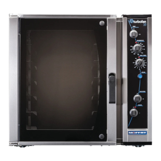
Operation Description of Controls Vent Vent closed with switch in the vertical position. Vent open with switch in the horizontal position. °C Thermostat Temperature range 100 - 550°F (60-280°C). Indicator illuminates when the elements are cycling ON to maintain set temperature. Bake Timer 1 Hour bake timer. -
Page 9: Baking
Operation Baking 1. Turn Power 'On' The indicator light will illuminate whenever the switch is in the “I” (On) position (the oven lights will also illuminate). The oven fan will start after 10 seconds with the door closed. The fan delay will repeat when- ever the door is closed after opening. -
Page 10: Door Handle
Operation Baking 8. Time Up When the timer reaches 0 minutes the buzzer will sound, and the indicator illuminates. To cancel the buzzer turn the timer to the off position. 9. Unload Oven Open the door and unload the oven . The oven fan will stop when the door is opened. -
Page 11: Removal Of Side Racks
Operation Side Racks 16 inch tray 1. The side racks can be fitted in one of two locator positions, in order to take 16 or 18 inch trays. 2. To position racks for 16 inch trays, use the holes at the rear of the rack. 3. -
Page 12: Cleaning
Cleaning Cleaning Guidelines AUTIO N ALWAYS TURN OFF THE POWER SUPPLY BEFORE CLEANING. THIS UNIT IS NOT WATER PROOF. DO NOT USE WATER JET SPRAY TO CLEAN INTERIOR OR EXTERIOR OF THIS UNIT. Exterior Clean with a good quality stainless steel cleaning compound. Harsh abrasive cleaners may damage the surface. -
Page 13: Faultfinding
Fault Finding A U T I O N This appliance is; • For professional use and is to be used by qualified persons only. • Only authorised service persons are to carry out installation, and servicing operations. • Components having adjustments protected (e.g. paint sealed) by the manufacturer should not be adjusted by the user / operator. -
Page 14: Circuit Schematics
Circuit Schematic 208V-220V, 3P+E 230-240V, 3P+E... - Page 15 Circuit Schematic 208-220V, 1P+N+E 230-240V, 1P+N+E...
-
Page 16: Circuit Schematic
Circuit Schematic 380V, 3P+N+E GREY GREY 400-415V, 3P+N+E GREY GREY BROWN BLUE BLACK GREEN/RED YELLOW WHITE... -
Page 17: Replacement Parts List
Selector Switch (Power). 231764 Solid State Thermostat. 020883K Thermostat Probe. 020823 Control Panel Knobs. Gear Plate 231740 Heating Contactor E35-xx-x253 / 263 (3P+E) Models Only. 231739 Heating Contactor 1P+N+E & 3P+N+E Models. 231741 Motor Contactor (3NO+1NO). 231742 Motor Contactor (3NO+1NC). - Page 18 Rack Runner 8 Tray LH WA (E35-26”). 025090 Rack Runner 8 Tray RH WA (E35-26”). 023118 Side Rack L / Hand WA 8 Tray (E35-30”). 023119 Side Rack R / Hand WA 8 Tray (E35-30”). 026590 Rack Runner 4 Tray L / Hand WA (E35-30”).
Need help?
Do you have a question about the E35 Series and is the answer not in the manual?
Questions and answers