
Related Manuals for Clarke CPT1000


Summary of Contents for Clarke CPT1000
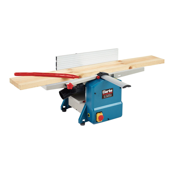
- Page 1 10” PLANER / THICKNESSER MODEL NO: CPT1000 PART NO: 6500870 OPERATION & MAINTENANCE INSTRUCTIONS LS0914...
- Page 2 INTRODUCTION Thank you for purchasing this CLARKE product. Before attempting to use this product, please read this manual thoroughly and follow the instructions carefully. In doing so you will ensure the safety of yourself and that of others around you, and you can look forward to your purchase giving you long and satisfactory service.
-
Page 3: Safety Warnings
SAFETY WARNINGS 1. Read and understand the entire 9. Some dust created by power owner's manual before attempting sanding, sawing, grinding, drilling assembly or operation. and other construction activities contain chemicals known to cause 2. Read and understand the cancer, birth defects or other warnings posted on the machine reproductive harm. - Page 4 15. Keep safety guards in place at all moving parts. Do not overreach or times when the machine is in use. If use excessive force to perform any removed for maintenance machine operation. purposes, use extreme caution 24. Use the right tool at the correct and replace the guards speed and feed rate.
- Page 5 33. The hands must never be closer than 75mm to the cutterhead 34. Never apply pressure to stock directly over the cutterhead. This may result in the stock tipping into the cutterhead along with the operator's fingers. Position hands away from extreme ends of stock, and push through with a smooth, even motion.
-
Page 6: Safety Symbols
SAFETY SYMBOLS Read this instruction booklet carefully before positioning, operating or adjusting the machine. Wear eye protection Wear ear protection Wear a dust mask that is specially designed to filter microscopic particles. CAUTION: THIS MEANS THAT IF PRECAUTIONS ARE NOT HEEDED, IT MAY RESULT IN MINOR INJURY AND/OR POSSIBLE MACHINE DAMAGE. -
Page 7: Electrical Connections
ELECTRICAL CONNECTIONS WARNING: READ THESE ELECTRICAL SAFETY INSTRUCTIONS THOROUGHLY BEFORE CONNECTING THE PRODUCT TO THE MAINS SUPPLY. Connect the mains lead to a standard, 230 Volt (50Hz) electrical supply through an approved 13 amp BS 1363 plug, or a suitably fused isolator switch. If the plug has to be changed because it is not suitable for your socket, or because of damage, it must be removed and a replacement fitted, following the wiring instructions shown below. -
Page 8: Planer Setup
PLANER SETUP WARNING: DISCONNECT MACHINE FROM POWER SOURCE BEFORE MAKING ANY ADJUSTMENTS. FAILURE TO COMPLY MAY CAUSE SERIOUS INJURY. FITTING THE FENCE 1. Position the fence as shown. 2. Lock the fence in place using the two hexagon screws supplied. FENCE POSITION ADJUSTMENT 1. -
Page 9: Fit The Dust Extractor Assembly
FIT THE DUST EXTRACTOR ASSEMBLY NOTE: The planer/thicknesser will NOT work if the dust extractor assembly is not fitted correctly. 1. Temporarily attach the table elevating handle and lower the table as far as possible, remove the table elevating handle. 2. -
Page 10: Thicknesser Setup
THICKNESSER SETUP FIT THE DUST EXTRACTOR ASSEMBLY NOTE: The planer/thicknesser will NOT work if the dust extractor assembly is not fitted correctly. 1. Remove the fence and put the dust extractor assembly into position as shown. 2. Engage the two locking clips (one on each side) into the slots on the side of the table. -
Page 11: Operating Controls
OPERATING CONTROLS POWER START Raise the cover of the ON/OFF switch and press the green ON button, marked ‘I’, and allow the machine to come up to full speed before use. STOP To switch OFF, simply press the red button marked ‘O’ and close the cover ensuring it is properly latched. -
Page 12: Infeed Table Height Adjustment
THE PLANER WARNING: DISCONNECT THE MACHINE FROM THE POWER SOURCE BEFORE MAKING ANY ADJUSTMENTS. FAILURE TO COMPLY MAY CAUSE SERIOUS INJURY. ADJUSTMENTS INFEED TABLE HEIGHT ADJUSTMENT 1. Rotate the Infeed Table Height Adjustment knob to set the difference in height between the infeed and outfeed tables. - Page 13 FENCE BEVEL ADJUSTMENT The fence can be tilted backwards up to a maximum of 45 1. Loosen the bevel lock handle. 2. Set the fence at the required angle. • Use the scale (0 - 45 ) and pointer shown. 3.
-
Page 14: Hand Placement
HAND PLACEMENT When you start, 1. The left hand holds the workpiece down on the infeed table and against the fence while the right hand pushes the workpiece over the cutterhead. • Use a smooth and even speed. 2. As the workpiece travels over the cutterhead, the new surface rests on the outfeed table, at this point the left hand should be transferred to the outfeed side and presses down on the workpiece on this side. -
Page 15: Edge Jointing
EDGE JOINTING Edge jointing is the process of creating a finished, flat edge surface that is suitable for joinery or finishing. It is also a necessary step prior to ripping stock to width on a table saw. • Always use a push stick when edging a board that is shorter than 300 mm, narrower than 75mm or less than 6mm thick. -
Page 16: Before Use
THE THICKNESSER WARNING: DISCONNECT MACHINE FROM POWER SOURCE BEFORE MAKING ANY ADJUSTMENTS. FAILURE TO COMPLY MAY CAUSE SERIOUS INJURY. BEFORE USE TABLE HEIGHT ADJUSTMENT 1. Rotate the table elevating handle to raise/lower the table. • 1 complete turn = 3 mm. 2. -
Page 17: Using The Thicknesser
USING THE THICKNESSER WARNING: ALWAYS WEAR ANSI-APPROVED SAFETY GLASSES OR GOGGLES WHEN OPERATING EQUIPMENT PRECAUTIONS • Do not try and mill dirty boards, dirt and stones may damage the blades. • Remove all nails and staples from the wood before thicknessing. PREPARING THE WORK 1. -
Page 18: Maintenance
MAINTENANCE WARNING: REMOVE THE PLUG FROM THE MAINS POWER SUPPLY BEFORE CARRYING OUT ANY ADJUSTMENT. SERVICING OR MAINTENANCE PERIODICALLY • Wipe both the infeed and outfeed rollers with a damp cloth to remove all traces of contaminants. • Apply a thin film of wax to the table periodically. This will help keep the table clean and allow the workpiece to slide more easily. -
Page 19: Replacing Cutter Blades
6. Turn the cutter block by 180 degrees and repeat the process. • ALWAYS replace cutter blades as a pair. NOTE: Spare blades are available from the Clarke spares department. Part number NXCPT1000110. 7. Replace in reverse order, and, using a straight edge, ensure the... -
Page 20: Drive Belt Replacement
6. Rotate the large belt wheel by hand in a clockwise direction whilst guiding the belt on to the belt wheel. NOTE: Spare drive belts are available from the Clarke spares department. -Part number NXCPT1000086. Parts & Service: 020 8988 7400 / E-mail: Parts@clarkeinternational.com or Service@clarkeinternational.com... -
Page 21: Specifications
SPECIFICATIONS Model Number CPT1000 Cutterhead Speed 8500 rpm Dust Port Diameter (Id/od) 68.5/76 mm Planer Max Stock Removal 2 mm Max Cutting Width 254 mm Fence Size 610 x 125 mm Fence Angle Range 90°- 135° Thicknesser Maximum Width 254 mm... -
Page 22: Declaration Of Conformity
DECLARATION OF CONFORMITY Parts & Service: 020 8988 7400 / E-mail: Parts@clarkeinternational.com or Service@clarkeinternational.com... -
Page 23: Also Available From Your Clarke Dealer
ALSO AVAILABLE FROM YOUR CLARKE DEALER Parts & Service: 020 8988 7400 / E-mail: Parts@clarkeinternational.com or Service@clarkeinternational.com...
Need help?
Do you have a question about the CPT1000 and is the answer not in the manual?
Questions and answers