Table of Contents
Advertisement
Advertisement
Table of Contents

Related Manuals for Clarke MetalWorker CDP151B


Summary of Contents for Clarke MetalWorker CDP151B
- Page 1 SERIAL No....0307...
- Page 2 When disposing of this product, do not dispose of with general waste. It must be disposed of according to law at a recognised disposal facility.
-
Page 3: Table Of Contents
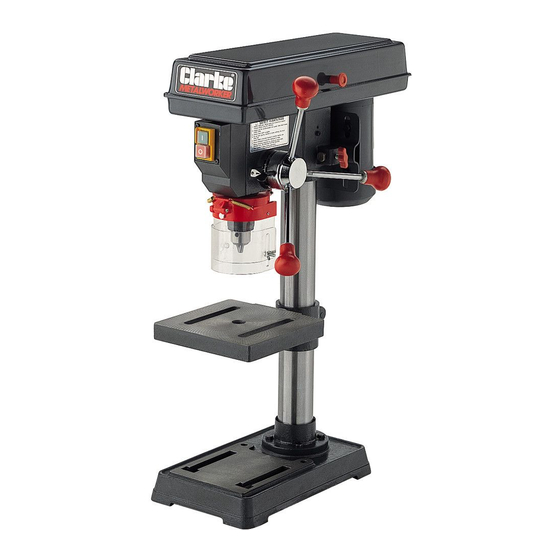
INTRODUCTION Thank you for purchasing your CLARKE - CDP 151B, 13mm bench mounted Drill Press. Before attempting to operate the machine, please read this instruction manual thoroughly, and follow all directions carefully. By doing so you will ensure the safety of both yourself and others around you, and at the same time, you should look forward to long and trouble free service from your Clarke Drill Press. -
Page 4: Safety Precautions
GENERAL SAFETY PRECAUTIONS WARNING As with all machinery, there are certain hazards involved with their operation and use. Exercising respect and caution will considerably lessen the risk of personal injury. However, if normal safety precautions are overlooked, or ignored, personal injury to the operator, or damage to property may result. KNOW YOUR MACHINE. -
Page 5: Additional Safety Rules For Drill Presses
19. DO NOT STAND ON THE MACHINE. Serious injury could occur if the machine is tipped over. Do not store materials above or near the machine such that it is necessary to stand on the machine to get to them. 20. -
Page 6: Electrical Connections And Wiring Diagram
ELECTRICAL CONNECTIONS Connect the mains lead to a standard, 230 Volt (50Hz) electrical supply through an approved 13 amp BS 1363 plug, or a suitably fused isolator switch. WARNING! THIS APPLIANCE MUST BE EARTHED IMPORTANT: The wires in the mains lead are coloured in accordance with the following code: Green &... -
Page 7: Preparation For Use
Box of loose parts Chuck Guard Assy. Check the parts against the above list and refer to the following diagrams. Should there be any deficiencies or damage, you should contact your CLARKE dealer immediately . Loose Items in Box and Bag... -
Page 8: Description Of Parts
Remove all traces of preservative from the components with paraffin or a good quality solvent, and wipe all parts thoroughly with a clean dry cloth. Apply a coating of wax paste or light oil, to the table, column and base, to prevent rust. Take the necessary precautions when lifting components, considering their weight. -
Page 9: Assembly
ASSEMBLY CAUTION! IT IS ADVISED THAT ASSISTANCE BE USED WHEN ASSEMBLING THIS MACHINE. A. Column to the Base. Fig. 1 Bolt the column assembly to the base with the four M8 x 20mm hex. screws provided. NOTE: Ideally, the base with column attached, should be firmly bolted to the workbench, prior to the assembly of other components. - Page 10 D. Chuck Guard Assembly Slide the Chuck Guard over the Quill Shaft and nip up the pinch bolt, temporarily, with the pinch bolt facing the front (see fig.4). Ensure the Quill Shaft/Spindle is at the top of its travel. NOTE: This operation should be carried out before the chuck is installed. E.
-
Page 11: Settings And Adjustments
SETTINGS and ADJUSTMENTS 1. Table. Fig. 7 The table may be raised, lowered or swivelled about the column, by slackening off the table support locking handle, (Fig. 7), adjusting accordingly, and re-tightening the handle. Fig. 8 Table Support Locking Handle It may also be tilted by loosening the screw, which secures the table to its’... -
Page 12: Drill Speed Table
3. Changing Drill (Spindle) Speed. Fig. 11 Before changing the speeds, ensure the machine is switched OFF and disconnected from the mains supply. Slacken off the Belt Tension Locking Screw (see fig.5), to relieve any tension on the drive belt. Open the pulley cover. -
Page 13: Operation
A Micro switch is provided within the Pulley Cover, which prevents the machine from operating unless the Pulley Cover is firmly closed. Drill Press Vices, Cross Vices and Clamps, are available from your CLARKE dealer. -
Page 14: Maintenance
If the mains lead is worn or cut, or damaged in any way, it should be replaced immediately. Please refer to the trouble shooting chart on page 13 . If you are unable to rectify any faults, please contact your local dealer or Clarke International Service Division on 020 8556 4443 for assistance. -
Page 15: Trouble Shooting
F) Pulley Cover not closed. G) Micro Switch inoperative. G) Check operation of micro switch, per instructions Page 10. If switch operates correctly but motor fails to start consult your Clarke dealer Drill binds A) Excessive feed pressure A) Apply less pressure in workpiece... -
Page 16: Parts Lists And Diagrams
PULLEY ASSEMBLY Item Description Part No Item Description Part No. Knob DD16105008 Rubber Bushing DD20105012 Retaining Ring DDGB8941-86 Pan Head Screw M5 3040656 Bearing 60203 BRG60203 Motor Pulley DD13205005 Spacer DD13302023 Hex Skt Screw M6 3040487 Pulley Insert DD13202022 Pulley Cover DD13205000 Bearing 80201 BRG80201... -
Page 17: Base Assembly
BASE ASSEMBLY Item Description Part No Column DD13201002 Hex. Head Screw M8 3040501 Base DD13201001 Table Tilt Locking Screw 3040510 Table Support w/Scale DD13201004A Clamp Handle DD16101013 Table DD13201014... -
Page 18: Head Assembly
HEAD ASSEMBLY Item Description Part No Item Description Part No. 1 Head w/Pointer and Trim DD13202001 19 Stop Pin DD13304010 2 Motor Assembly DDYYG71L4(W) 20 Connector DD13302019 3 Hex. Nut M8 3040601 21 Lockwasher DDGB8621-87 4 Washer DDGB972-85 22 Pan Head Screw M5x6 3040485 5 Motor cable DD13202016... -
Page 19: Specifications
CLARKE dealer SPARE PARTS & SERVICING For Spare Parts and Service, please contact your nearest dealer, or CLARKE International, on one of the following numbers. PARTS & SERVICE TEL: 020 8988 7400 PARTS & SERVICE FAX: 020 8558 3622 e-mail as follows: PARTS: Parts@clarkeinternational.com...
Need help?
Do you have a question about the MetalWorker CDP151B and is the answer not in the manual?
Questions and answers