Mitsubishi Electric DX-TL2500E Installation And Operation Manual
Digital recorder
Hide thumbs
Also See for DX-TL2500E:
- Operation quick manual (28 pages) ,
- Operation manual (32 pages) ,
- How to use manual (10 pages)
Table of Contents
Advertisement
Quick Links
Download this manual
See also:
Operating Manual
Advertisement
Table of Contents
Troubleshooting

Related Manuals for Mitsubishi Electric DX-TL2500E


Summary of Contents for Mitsubishi Electric DX-TL2500E
- Page 1 DIGITAL RECORDER INSTALLATION AND OPERATION MANUAL MODEL DX-TL2500E THIS INSTRUCTION MANUAL IS IMPORTANT TO YOU. PLEASE READ IT BEFORE USING YOUR DIGITAL RECORDER.
-
Page 2: Features
Features Built-in duplex 16 channel multiplexer • The screen mode can be switched on the monitor such as single screen, split4, split9 and split16 screen and sequential screen, split4 sequential screen and split9 sequential screen. ( see page 37) • The unit is equipped with the 2 type-output connector to display the different mode split screen on the each of different monitors. - Page 3 Ease of use • Auto set-up By selecting only the recording period of 24, 96 or 168 hrs. and 14 or 30 days, the unit assigns automatically recording interval and picture grade for all channels and other menu settings are set to the default. ( pages 17,18) •...
-
Page 4: Caution And Care
Caution and care HEAVY OBJECTS SHOULD NEVER BE PLACED ON THE UNIT (E.G., TV) NEVER TOUCH OR INSERT ANY OBJECT INSIDE THE UNIT Touching the inside of the cabinet or inserting foreign objects of any kind not only creates a safety hazard but can also cause extensive damage. - Page 5 MAINS LEAD CONNECTION The mains lead on this Unit is fitted with a non-rewireable mains plug, incorporating a 5A fuse. If you need to replace the fuse, use a 5A fuse approved by BSI or ASTA to BS 1362, ensuring you refit the fuse cover.
-
Page 6: Table Of Contents
Contents Features ..............2,3 ZOOM button operations ..........36 The function of the SPLIT/SEQUENCE button, Caution and care ........... 4,5 ZOOM button, and camera number buttons ... 37 Contents ..............6,7 MPX DISPLAY SETTINGS ..........38 Flowchart ............... 8,9 SPLIT/SEQUENCE ............38 Flowchart for connection and settings ...... - Page 7 CAMERA CONTROL ............57 The personal computer product requirements .... 82 INFORMATION/SERVICE ........... 57-59 Connections ..............82 HDD INFORMATION/ARCHIVE/COPY AUTHENTICATION ..........82-83 INFORMATION/CFC INFORMATION ..57,58 Welcome ..............83-87 WARNING LOG LIST ..........58 Live monitor ............83,84 RESET TO FACTORY SETTINGS ......58,59 Playback ............
-
Page 8: Flowchart
Flowchart Flowchart for connection and settings Installation example : This is an example operational flowchart of the following : making connections at the rear of the terminal ; setting HDD mode to PARTITION ; making default settings ; making an Alarm recording with Timer mode ; searching recorded data with ALARM LIST SEARCH ;... - Page 9 Changing the multiplexer function Setting the timer recording (continued) • Changing the split4 , split9 and split16 screen settings. • Setting the timer program mode. See “ SPLIT4 SCREEN SETTING”, page 38, See “<TIMER PROGRAM SETTINGS>”, “ SPLIT9 SCREEN SETTING”, page 39 and “ pages 46-48.
-
Page 10: Major Operations And Their Functions
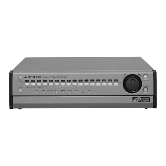
Major operations and their functions Front View ENTER/ CLEAR/ DIGITAL RECORDER DX - TL 2500 SPLIT/ REC/STOP SEQUENCE ARCHIVE ZOOM OUTPUT B TIMER PRE ALARM M-DET EMERGENCY ACCESS LOCK Multiplex Digital Record & 14 15 16 1. ZOOM button 7. ARCHIVE button When pressing this button once during single screen Press the button to archive. -
Page 11: Front View (Inside Of The Door)
Front View (Inside of the door) 17 18 19 CLEAR/ ENTER/ DIGITAL RECORDER DX - TL 2500 SPLIT/ REC/STOP SEQUENCE ARCHIVE ZOOM OUTPUT B TIMER PRE ALARM M-DET EMERGENCY ACCESS LOCK PAUSE/ POWER TIMER VIDEO OUT AUDIO OUT COMPACT FLASH STOP REV. -
Page 12: Inserting/Ejecting Compact Flash Card
Major operations and their functions (continued) Front View (Inside of the door) (continued) 17 18 19 ENTER/ CLEAR/ DIGITAL RECORDER DX - TL 2500 SPLIT/ REC/STOP SEQUENCE ARCHIVE ZOOM OUTPUT B TIMER PRE ALARM M-DET EMERGENCY ACCESS LOCK POWER TIMER VIDEO OUT AUDIO OUT PAUSE/ COMPACT FLASH... -
Page 13: Rear View
Rear View CAMERA MAIN AC IN OUTPUT A OUTPUT B AUDIO ALARM IN VIDEO RS-232C ETHERNET REMOTE SCSI RESET RS-485/ RECEIVE SEND RS-422 1. MAIN switch 8. VIDEO OUT connectors This is the main power switch. When using this unit, OUTPUT A VIDEO connector set this switch to ON. -
Page 14: Major Operations And Their Functions
Major operations and their functions (continued) Rear View (continued) CAMERA MAIN AC IN OUTPUT A OUTPUT B AUDIO ALARM IN VIDEO RS-232C ETHERNET REMOTE SCSI RESET RS-485/ RECEIVE SEND RS-422 REC terminal 16. SCSI connector Input terminal to start recording. Not available dur- This connector is used to connect to peripheral re- ing timer recording. -
Page 15: Connections
Connections Connecting to CCTV camera, monitor, sensor VIDEO MONITOR To VIDEO IN or S(Y/C) IN connector To OUTPUT A VIDEO or OUTPUT A S(Y/C) connector CAUTION One of either codes When a microphone is should be connected. connected to the MIC jack, To AUDIO IN the MIC jack will be given CAUTION... -
Page 16: Alarm Recording Connection
Connections (continued) Usable cables Alarm Recording Connection Connections between the unit and its peripherals are made The diagram below shows an example of con- Example : using standard SCSI cables. nection for alarm signals corresponding to camera number 1. (In the case of ALARM SETTING of default Connection when using 1 peripheral recording setting.) device... -
Page 17: Auto Set Up
Connections /AUTO SET UP (continued) SCSI number chart 3. Turn the JOG dial to display the desired setting and turn the SHUTTLE ring clockwise. Connected SCSI ID Purpose Notes ID4 • ID5 • The setting is confirmed and flashing stops. device Number Beware while setting the AUTO SET UP, the menu... -
Page 18: Initial Settings
/ Initial settings AUTO SET UP (continued) 11. When the setting is complete, press the POWER button. To execute AUTO SET UP again, press and hold • “SETTING UP...” is displayed on the screen, and the unit the ARCHIVE button and press the POWER button, starts-up. -
Page 19: Hdd Setting
HDD SETTING The HDD SETTING can be set to MIRRORING (simulta- neous recording to the internal HDD and peripheral record- ing device HDD as a pair), PARTITION (an independent partition that can be set within the total HDD memory spe- cifically for ALARM RECORDING) and LONG PRE-ALARM (Long-term pre-alarm recording is possible for maximum 30 minutes). -
Page 20: Basic Operations
Basic Operations Example : Set DISPLAY MODE to “3” ( default : “1” ). Multiplexer functions Buttons on the front of the unit can be used to perform 1. Set the MAIN switch on the rear of the unit to ON. Press some of the multiplexer functions. -
Page 21: To Return To The Normal Screen From A Menu Screen
<TIME DATE/DISPLAY SETTINGS> <TIME DATE ADJUST> TIME DATE ADJUST >>DAYLIGHT SAVING >>DISPLAY MODE CLOCK LOCATION SETTING MONTH CAMERA DISPLAY NUMBER YEAR 2003 CAMERA TITLE/MEMO SETTING TIME 00:00:00 DUPLEX MODE DISPLAY BOTTOM DAYLIGHT SETTING DAY OF WEEK MONTH TIME <MODE 3> LAST 01:00 OUT SUN... -
Page 22: Time Date Adjust
Basic Operations (continued) Present time display <TIME DATE ADJUST> When turning on the unit power, the time/date display shown DAYLIGHT SAVING to the right appears (in the case of DISPLAY MODE 3). >>DAY MONTH YEAR 2003 For setting other display modes, see “DIS- TIME 00:00:00... -
Page 23: Basic Manual Recording
Basic manual recording Normal recording using manual operation is explained here. <RECORD SETTING> 1/2 Camera selection during alarm recording Before starting recording, recording settings must be checked. After checking the settings of “HDD REPEAT REC <RECORD SETTING> ALARM CH MAIN”, “HDD REPEAT REC SUB” and “HDD REPEAT REC GRADE A-PPS A-GRADE >>... -
Page 24: Basic Playback
Basic Operations (continued) 10. Turn the SHUTTLE ring counterclockwise or press the SET The menu screen will not be cleared even when UP button to return to the normal screen. pressing the SET UP button when the setting item is flashing. 11. -
Page 25: Basic Search
3. To pause playback, press the PAUSE button. • To resume playback, press the PAUSE button again or press <TIME DATE SEARCH> the PLAY button. >>03-03-2003 21:25:40 4. To stop playback, press the STOP button. EXECUTE(FORWARD) • During HDD playback/pause, playback will start the next time from the paused position. -
Page 26: Language Selection
Basic Operations (continued) “LPA” is appeared on the screen when “LONG PRE- ALARM” is selected on “HDD SETTING” of the <INITIALIZATION> screen after installing 03-03-2003 21:25:40 EXTRA HDD to “INTERNAL HDD A”. 10-2. (To change the search type • • • ) Turn the JOG dial to select “SEARCH TYPE”... -
Page 27: Menu Functions
Menu functions MENU SETTING You can set the basic settings for this unit in the MENU SETTING. Refer to pages shown below for details. During playback, recording, pre-alarm recording stand-by mode you cannot change setting of some MENUs. SUB MENU (1) SUB MENU (2) <TIME DATE/DISPLAY SETTINGS>... - Page 28 Menu functions (continued) SUB MENU (1) SUB MENU (2) SET UP <MOTION DETECTION SETTINGS> <DETECTION MASK SETTING> Page 41 MAIN MENU Pages 41, 42 <TEST MODE> Page 42 4 5 6 10 11 13 14 15 16 <ALARM SETTING> 1/2 Pages 43, 44 <ALARM SETTING>...
- Page 29 SET UP MAIN MENU SUB MENU (1) SUB MENU (2) #2. Appears when “PARTITION” (“LONG PRE-ALARM”) is set on the screen. #3. Appears when “ARCHIVE•COPY” is set to ID4•ID5 on the screen. #5. Appears when “PARTITION” (“LONG PRE-ALARM”) and “ARCHIVE•COPY” are set respectively to ID4•ID5 on the screen.
- Page 30 Menu functions (continued) SET UP MAIN MENU SUB MENU (1) SUB MENU (2) <INITIAL SET UP/INFORMATION> <INFORMATION/SERVICE> 1/2 <INFORMATION/SERVICE> 2/2 Pages 49-61 Pages 57-59 SUB MENU (3) <QUICK SETTINGS> Page 62 <HDD INFORMATION> 1/2 Pages 57,58 <HDD INFORMATION> 2/2 <ARCHIVE/COPY INFORMATION> Pages 57,58 #2.
- Page 31 SET UP MAIN MENU SUB MENU (1) SUB MENU (2) <INITIAL SET UP/INFORMATION> <INFORMATION/SERVICE> 2/2 <INFORMATION/SERVICE> 1/2 Pages 57-59 Pages 49-61 SUB MENU (3) SUB MENU (2) SUB MENU (3) <MAIN HDD DATA CLEAR> Page 59 <PASSWORD> Pages 59-61 <PASSWORD SETTING> Pages 59-61 <SUB HDD DATA CLEAR>...
-
Page 32: Copy Menu
Menu functions (continued) COPY MENU MAIN MENU <COPY> <COPY> Pages 76, 77 <RESTORE> <RESTORE> Pages 76, 77 SEARCH SELECTION MENU SEARCH SUB MENU (1) MAIN MENU SEARCH <TIME DATE SEARCH> Pages 25, 26 <SEARCH SELECTION> Page 71 SEARCH <INDEX SEARCH> Pages 72, 73 <SEARCH SELECTION>... -
Page 33: Time Date/Display Settings
<TIME DATE/DISPLAY SETTINGS> TIME DATE ADJUST 2. Use the , , buttons to move the time and date to the desired display position and turn the SHUTTLE ring See pages 21, 22. clockwise. • The setting is confirmed. DISPLAY MODE Display format of the date and current time can be set. - Page 34 <TIME DATE/DISPLAY SETTINGS> (continued) 6. Repeat steps 3 ~ 5 to input “ENTRANCE” in the string. The <CAMERA TITLE/MEMO SETTING> screen • To erase an inputted character, move the cursor to the very consists of 2 pages. The second page is displayed when left character “...
-
Page 35: Duplex Mode Display
DUPLEX MODE DISPLAY Operation conditions such as PLAYBACK, COPY, REC and ALARM REC (ALARM is displayed in red during emergency recording), etc., can be displayed on the up- per or lower portions of the screen. Setting ( default : “BOTTOM” ) “BOTTOM”... -
Page 36: Mpx Display Settings
<MPX DISPLAY SETTINGS> The multiplexer function of this unit allows the connected The magnification display function can only be camera video to be displayed using SPLIT4, SPLIT9 and set when in the single screen mode. The screen can SPLIT16 screens. It is also possible to set the order of the be moved vertically and horizontally with the mag- camera number displayed. -
Page 37: The Function Of The Split/Sequence Button, Zoom Button, And Camera Number Buttons
The function of the SPLIT/SEQUENCE button, ZOOM button, and camera number buttons The screen of cameras with no video input signal will appear blue. Furthermore, the screen of cameras set to “OFF” for COVERT CAMERA SETTING will appear black ( see page 81). -
Page 38: Mpx Display Settings
<MPX DISPLAY SETTINGS> (continued) MPX DISPLAY SETTINGS When set the multiplexer setting of the <OUT- Multiplexer setting of the <OUTPUT A> screen for the moni- PUT B> screen the same as the setting of the <OUT- tor video and multiplexer setting of the <OUTPUT B> screen PUT A>... -
Page 39: Split9 Screen Setting
SPLIT9 SCREEN SETTING For the SPLIT9 SCREEN SETTING, 2 types of SPLIT9 screen types (a, d) can be set. 1. Press the SET UP button <SETTINGS> Select “OUTPUT A” (“OUTPUT B”) in the <MPX DISPLAY SETTINGS> screen and turn the SHUTTLE ring clockwise. •... -
Page 40: Sequence Setting
<MPX DISPLAY SETTINGS> (continued) 9-2. Display the desired item to set and turn the SHUTTLE ring clockwise. <SEQUENCE SETTING> 2/2 • Setting of “SPLIT9” ( default : SPLIT “ab” ) “ab” : SPLIT9(a) and (b) are displayed using sequence display. “a”... -
Page 41: Motion Detection Settings
<MOTION DETECTION SETTINGS> 1. In “SELECTION CAMERA NUMBER , select the camera In this menu, the conditions of the motion detection func- for setting the detection area. tion for normal recording and alarm recording, which is started when detecting motion within the video of the con- 2. -
Page 42: Sensitivity
<MOTION DETECTION SETTINGS> (continued) TEST MODE SENSITIVITY The set motion detection operation is tested here. The sensitivity of detection for changes in the loaded video data is set. The sensitivity setting is divided into the 5 lev- els of brightness. 1. -
Page 43: Record Settings
<RECORD SETTINGS> Settings concerning normal recording and The <ALARM SETTING> screen consists of 2 alarm recording pages. The second page is appeared when turning This unit allows independent settings for normal recording the JOG dial to move the cursor to “NEXT PAGE”, and alarm recording. -
Page 44: Pre Alarm Rec
<RECORD SETTINGS> (continued) When select and set the “TRIGGER” setting to Pressing the WARNING RESET button while the MD, MD/EXT or MD&EXT, the motion detection func- cursor is on the left of the desired camera number changes that camera’s “PPS” and “A-PPS” to “- - - - - -”. tion will be active soon and any setting alteration can not be accepted. -
Page 45: Alarm Rec Duration
ALARM REC DURATION This setting is displayed when “ARCHIVE•COPY” The recording time during alarm recording can be set. is selected on “ID4•ID5” on the <INITIALIZATION> screen. <RECORD SETTINGS> ALARM SETTING RECORD SETTING ARCHIVE OVERWRITE commences back up >> ALARM REC DURATION after all data on the ARCHIVE device is deleted. -
Page 46: Timer Program Settings
<TIMER PROGRAM SETTINGS> “OVER-E” : Performs archive after deleting all previous data TIMER PROGRAM SETTINGS on the ARCHIVE device, and automatically ejects media Up to 3 most used operation patterns can be set in ad- after completion of archive. vance. By individually setting the camera, recording inter- vals and recording picture quality for normal recording/ “CONT”... -
Page 47: Timer Program
5. Check to see that the cursor is to the left of program number 16. Turn the JOG dial to display “WED” in start day and turn “1” and turn the SHUTTLE ring clockwise twice. the SHUTTLE ring clockwise. • The “DW” display reverses in color when the SHUTTLE ring •... -
Page 48: Holiday Setting
<TIMER PROGRAM SETTINGS> (continued) HOLIDAY SETTING ALARM REC DURATION Holidays throughout the year can be set in advance. The recording time for alarm recording can be set (for details concerning setting ALARM REC DURATION, see page 45). <HOLIDAY SETTING> --/-- --/-- --/-- --/--... -
Page 49: Initial Set Up/Information
<INITIAL SET UP/INFORMATION> HDD SETTINGS <HDD SETTINGS> HDD REPEAT REC MAIN HDD REPEAT REC MAIN/HDD REPEAT REC HDD REPEAT REC SUB HDD REPEAT REC LPA SUB/HDD REPEAT REC LPA >> HDD REPEAT PLAY The operation when HDD (Hard Disk Drive) space becomes IM-CHECK PLAY SEQUENTIAL PLAY full during recording. -
Page 50: Im-Check Play
<INITIAL SET UP/INFORMATION> (continued) When performing camera sequential playback Warning will also be displayed for parts where for video with long recording intervals, the video of recorded data is damaged for some reason. the largest camera number selected for recording will be played back the longest. -
Page 51: Archive Start Position Reset
<HDD SETTINGS> <ARCHIVE START POSITION RESET> HDD REPEAT REC MAIN HDD REPEAT REC SUB >>EXECUTE HDD REPEAT REC LPA HDD REPEAT PLAY IM-CHECK PLAY SEQUENTIAL PLAY 2. Turn the SHUTTLE ring clockwise. FIFO OVERWRITE MODE >> ARCHIVE SOURCE HDD MAIN •... -
Page 52: Rear Terminal Settings
<INITIAL SET UP/INFORMATION> (continued) • Audio recording cannot be performed when “PPS” of 1. Press the SET UP button } <SETTINGS> } <INITIAL SET UP/INFORMATION> } Select “REAR TERMINAL “RECORD SETTING” are all set to smaller than “0.333P” when setting normal recording. In this case, SETTINGS”... -
Page 53: Remain Hdd
Setting ( default : “OFF” ) 1. Press the SET UP button } <SETTINGS> } <INITIAL SET UP/INFORMATION> } “Select “REMAIN HDD” in the <REAR “REMAIN”, “WARNING”, “ALARM”, “OFF” TERMINAL SETTINGS> screen and turn the SHUTTLE ring SETTING clockwise twice. REMAIN WARNING ALARM... -
Page 54: Hdd Main Full/Hdd Sub Full/ Hdd Lpa Full/Archive Full
<INITIAL SET UP/INFORMATION> (continued) 1. Press the SET UP button } <SETTINGS> } <INITIAL SET EMERGENCY REC DURATION UP/INFORMATION> } <REAR TERMINAL SETTINGS> } The recording time for emergency recording can be set. Select “HDD MAIN REMAIN”, “HDD SUB REMAIN”, “HDD <REAR TERMINAL SETTINGS>... -
Page 55: Settings
1. Press the SET UP button } <SETTINGS> } <INITIAL SET <ETHERNET> UP/INFORMATION> } <COMMUNICATION PORT >>IP ADDRESS 192.168.000.100 SETTINGS> } Select “MODE” in the <RS-232C> screen. SUB NET MASK 255.255.255.000 GATEWAY 000.000.000.000 Display the desired setting and confirm. E-MAIL ADDRESS SERVICE PORT SETTING 2. -
Page 56: Service Port Setting
<INITIAL SET UP/INFORMATION> (continued) • SERVICE PORT SETTING <ALARM NOTIFICATION SETTING> The port number can be set here to connect personal IP ADDRESS TARGET OWN >>1 000.000.000.000•55111 01111 computer. 2 000.000.000.000•55111 01112 3 000.000.000.000•55111 01113 4 000.000.000.000•55111 01114 Do not change the setting without sufficient knowl- 5 000.000.000.000•55111 01115 edge about the network setting. -
Page 57: Camera Control
9. When the setting is altered, the unit turns off automatically The <INFORMATION/SERVICE> screen consists and the setting will renew. of 2 pages. The second page is appeared by turning the JOG dial clockwise when the cursor points out the CAMERA CONTROL setting of the bottom of the screen. -
Page 58: Warning Log List
<INITIAL SET UP/INFORMATION> (continued) 1. Press the SET UP button } <SETTINGS> } <INITIAL SET When “LONG PRE-ALARM” has been set for “HDD UP/INFORMATION> } Select “WARNING LOG LIST” in the SETTING”, the <HDD INFORMATION> menu becomes <INFORMATION/SERVICE> screen. Turn the SHUTTLE ring a 2-screen menu. -
Page 59: Information/Service
PASSWORD <RESET TO FACTORY SETTINGS> The unit is equipped with 2 lock functions : SIMPLE LOCK that does not require the PASSWORD when un- >>EXECUTE locking and PASSWORD LOCK that require the PASS- WORD when unlocking. • If the PASSWORD for unlocking has not been set : Lock function will be SIMPLE LOCK SHUTTLE>>:EXECUTE,<<:CANCEL •... - Page 60 <INITIAL SET UP/INFORMATION> (continued) 2-4. Input the PASSWORD entered in “FIRST” in “SECOND”. When The PASSWORD LOCK of level 3 is active, • The cursor moves to the left side of the setting of level 1. it is operable except the SET UP button and ALARM INTERRUPT button.
-
Page 61: Language Selection
2-1. (To change the PASSWORD for level 1 to 3 • • • ) When the PASSWORD LOCK of level 1 and 2 are Display the <PASSWORD SETTING> (level 1 to level 3) set, if unlock level 1 the PASSWORD LOCK of level 2 screen. -
Page 62: Quick Settings
<QUICK SETTINGS> 6. Press the POWER button to turn the unit off, then press it QUICK SETTINGS once more to turn the unit back on. Menu settings stored on the Compact Flash Card can • The setting is confirmed. be read and altered with the unit. Menu settings in the unit can be copied to the Compact Flash Card. -
Page 63: Operation Examples
Operation examples Operation example 1 <HDD SETTINGS> This example illustrates the procedure for switching be- >>HDD REPEAT REC MAIN tween cameras according to time and day, when different HDD REPEAT REC SUB HDD REPEAT PLAY numbers of cameras are allocated to RECORD SETTINGS IM-CHECK PLAY A and B for normal recording in Timer record mode. -
Page 64: Operation Example 1
Operation examples (continued) < Setting > <RECORD SETTING B> 2/2 1) <CAMERA TITLE/MEMO SETTING> screen setting <RECORD SETTING B> ALARM CH see pages 33, 34). GRADE A-PPS A-GRADE >> ------ STD ------ STD • Camera number “ ” ~ “ ”. -
Page 65: Operation Example 2
< Setting > 6) <RECORD SETTING B> screen setting ( see page 48). 1) Set 1) ~ 3) of “Operation example “ 1 ” above. • Camera number “ ”, “ ”, “ ”, “ ”, “ ” and “ ”... - Page 66 Operation examples (continued) <ALARM SETTING C> 2/2 <ALARM SETTING D> 2/2 <ALARM SETTING C> ALARM CH <ALARM SETTING D> ALARM CH ALARM RECORD CAMERA TRIGGER ALARM RECORD CAMERA TRIGGER 10 10 >>10 --------- ------ MD/EXT 10 10 >>10 --------- ------ EXT ---------- ----- MD/EXT 11 11 ---------- ----- EXT...
-
Page 67: Operation Example 4
4) <RECORD SETTING A> screen setting ( see page 48 ). Operation example 4 This example illustrates the procedure for when the unit is • All cameras ( “ ” ~ “ ” ). • PPS, GRADE : Set desired interval and picture quality set to record from Monday to Friday, and archive the data for each camera. -
Page 68: Various Recordings
Various recordings PRE ALARM RECORDINGS 2) Cameras used • Recording is performed using all cameras other than those During alarm recording, recording can be started a few set to “- - - - - -” in “PPS” and “- - - - - -” in “A-PPS”. seconds before the ALARM IN terminal is grounded or motion is detected. -
Page 69: Various Playback Functions
Various playback functions Playing still frames During frame feeding in the single screen mode, the frame feeding operation may not operate cor- 1. Press the PAUSE button during playback. rectly when the JOG dial is turned too fast since • The unit switches to still frame playback. Press the button frame feeding is performed while searching the video again to resume playback. -
Page 70: Monitor Display Settings And Playback Operation
Various playback functions (continued) 2-2. Press the REV. PLAY (REVERSE PLAYBACK) button. • The playback interval is changed to a slower setting (25P, 12.5P, and so on) each time the button is pressed. Audio cannot be played back when changing the playback interval. -
Page 71: Various Search
Various search The various search functions of this unit can be used to 1. Press the SEARCH button twice to display the <SEARCH skip to the beginning of the desired video. SELECTION> screen. 2. Display the desired setting in “SELECTION CAMERA SEARCH SELECTION NUMBER”... -
Page 72: Time Date Search
Various search (continued) TIME DATE SEARCH See pages 25, 26. INDEX SEARCH/ALARM INDEX SEARCH With this unit, index signals are automatically written to the HDD at the start of each recording. It is possible to search these signals and playback start- ing at such index points. -
Page 73: Alarm Skip Search
To change the desired camera number to the single screen dis- play during still-frame playback in SPLIT16 display, press the SEARCH button to clear the search setting screen and press the desired cam- era number button. Search may not perform properly at times depending on the re- corded condition of the index signals. -
Page 74: Alarm List Search
Various search (continued) ALARM LIST SEARCH When the correspondent cameras for alarm sig- This unit stores the start time of alarm recording and emer- nals are not set for the recording, the record is gency recording in the alarm list when such recording be- storaged using the camera of the youngest number. -
Page 75: Start/End Search
START/END SEARCH It is possible to search the recording starting/ending point of the device (media) selected by pressing the PLAY DE- VICE button in <TIMER DATE SEARCH>, <INDEX SEARCH> and <ALARM INDEX SEARCH> for playback. 1. Press the SEARCH button. •... -
Page 76: Making Copy/Restore
Making Copy/Restore 1-3. Display “MAIN HDD } CFC”, “SUB HDD } CFC” and Making Copy/Restore “LPA HDD } CFC” on “DIRECTION” and confirm. Data in MAIN HDD or SUB HDD can be copied to a COPY device or Compact Flash Card. Data in ARCHIVE/COPY <COPY>... -
Page 77: Copying From Unit To Videotape
When “DIRECTION”, and “OVERWRITE” on The image data is administrated in 1MB unit. “MODE”, all data on the Compact Flash Card re- Therefore the data is copied in 1MB unit included gardless of menu division is overwritten. the designated range when copy. 5. -
Page 78: Other Convenient Functions
Other convenient functions 2. Select “HDD SETTING” by turning the JOG dial, display the Power failure compensation circuit “MIRRORING” setting, and turn the SHUTTLE ring clockwise. The unit is equipped with an internalized power failure com- pensation circuit. When the unit has been charged for 48 <INITIALIZATION>... -
Page 79: Partition/Partition Size
PARTITION/PARTITION SIZE Points to be aware of regarding PARTITION PARTITION mode only uses the internal HDD, and pe- mode ripheral recording device HDD’s. PARTITION mode des- • Either “MAIN” or “SUB” can be selected for ar- ignates the area inside the HDD that is specified as each chive/copy. -
Page 80: Long Pre-Alarm
Other convenient functions (continued) LONG PRE-ALARM Points to be aware of regarding LONG PRE- This function can be used to perform pre-alarm record- ALARM mode ing for a maximum of 30 minutes before the start of • With operation in LONG PRE-ALARM mode, the emergency recording by using the LONG PRE-ALARM “INTERNAL HDD A”... -
Page 81: Covert Camera Setting
3. Turn the JOG dial to select “OFF” and turn the SHUTTLE COVERT CAMERA SETTING ring clockwise. The video of the specified camera number can be set to • The setting is confirmed and flashing stops. not be displayed regardless of the presence of video •... -
Page 82: Communications By Web Browser
Communications by Web Browser AUTHENTICATION Communications by Web Browser Start up the Microsoft Internet Explorer and log in. The Web browser on the personal computer can cap- ture the pictures that have been recorded and live pic- 1. Start up the Microsoft Internet Explorer and enter the tures from the camera that is connected to this equip- address. -
Page 83: Welcome
3-1. (If you make an error in entering the userID or password • • • ) • The “[Rejection]” screen will appear. 3-2. Select “[Back to Authentication]” and either left-click or press ENTER. • The “[Authentication]” screen will appear. 3-3. Follow the steps in step 2-1 and enter the correct “userID” and “password”. -
Page 84: Playback
Communications by Web Browser (continued) Setting “Transfer Rate” too far on “Hi” may present obstacles to PC operation as determined by the performance of the PC you are using. Please set it to the appropriate rate to the image retrieval speed of your machine. -
Page 85: Time Search
: Press to start speed searches in the reverse direction at speeds of x2, x4, x8 and x16. : Press to frame-by-frame playback in the re verse direction. : During playback or searching, press to stop playback for still frame. Device : Selects the HDD for playback and search. -
Page 86: Log Out
Communications by Web Browser (continued) <User authorization> 4-1. (To register a new user • • • ) Enter the new userID and new password in “Register new Live Monitor : Allows acquisition of live images. user”. It is a mandatory rank to be regis 4-2. - Page 87 2-1. (To change the logged in user • • • ) In the “Log in ( or log in as a different user ):” settings, execute step 2-1 and 2-2 in “ AUTHENTICATION” and change the logged in user. • The logged in user is changed and the “Welcome” screen appears.
-
Page 88: Recording Time Table
Recording time table Continuous recording time table HDD continuous recording time (for 120GB drive) Displays the estimated recordable time (when recording on a 120GB HDD). The following table shows estimated recordable time when operating with 2 cameras and the recording interval is set at a constant PPS rate given at the top of the column. •... -
Page 89: Compact Flash Card Continuous
Compact Flash Card continuous recording time (for 64MB) Displays the estimated recordable time (when recording on a 64MB Compact Flash Card). • Without Audio recording NUMBER OF 12.5P 8.333P 6.25P 4.167P 3.125P 2.5P 0.5P 0.25P 0.125P RECORDING GRADE FIELD SUPER 1m10s 1m30s 2m20s... -
Page 90: Troubleshooting
Troubleshooting If problems with the unit persist even after you’ve followed the suggestions below, please disconnect the power cord and contact the retailer from whom you purchased the unit. Description of problem Please consult the following Page The unit will not turn on. •... -
Page 91: Troubleshooting
Description of problem Please consult the following Page The copy device/archive • Has the recording medium been inserted correctly into the unit? device dose not respond. • Is the unit currently in the middle of loading the recording medium? • Is the correct playback device selected? 24, 71 •... -
Page 92: Warnings And Call Out Output
Warnings and CALL OUT output Warnings and their appropriate countermeasures #1 Options in the CALL OUT options column: • Selectable : CALL OUT output can be selected/de-selected on the menu. • Fixed : a CALL OUT signal is emitted without prior selection of this function using the menu. •... - Page 93 CALL OUT Canceling Status Code page Warning Display Countermeasure output the warning Fixed when 49, 50 IMAGE MODIFIED • Video data that has been Press the WNG5500 altered was played back. WARNING setting is “ON” RESET button. SYSTEM ERROR • System error has •...
-
Page 94: Glossary
Glossary • Hard disk drive (HDD) Glossary Storage device using the same magnetic recording proc- ess as tapes and is used in PCs. An aluminium disk coated • I/O terminals with magnetic materials is used on the surface as the stor- Terms used for referring to both input and output. -
Page 95: Specifications
Specifications Rated Power Supply: AC 100-240V 50/60Hz Rated Input: 0.65 - 0.3A (100-240V) Color System: PAL type color system. Operating Temperature: 41 F-104 F (5 C to 40 C). Relative Humidity: Max.80(%) Altitude: Max.2000(m) Dimensions: 425(Width) x 375(Depth) x 118(Height)(mm). Weight: 7.5kg Recording System... - Page 97 Others DEUTSCH STELLEN SIE NIEMALS SCHWERE GEGENSTÄNDE AUF DEN REKORDER (z. B. EIN FERNSEHGERÄT) STECKEN SIE NIEMALS GEGENSTÄNDE IN DEN REKORDER Gegenstände, die innen am Gehäuse anstoßen, oder alle eingesteckten Fremdkörper sind nicht nur gefährlich sondern verursachen auch große Beschädigung. SCHÜTZEN SIE DAS NETZKABEL Ein defektes Netzkabel kann Brand oder elektrischen Schlag verursachen.
- Page 98 Others (Continued) FRANÇAIS INTERDICTION DE POSER DES OBJETS LOURDS SUR L’ENREGISTREUR (PAR EX: TÉLÉVISEUR) INTERDICTION DE TOUCHER L’INTÉRIEUR DE L’ENREGISTREUR ET D’Y INTRODUIRE TOUT CORPS ÉTRANGER Tout contact avec l’intérieur du boîtier ou toute introduction de corps étranger peut non seulement constituer un danger mais peut également entraîner d’importants dégâts.
- Page 99 CASTELLANO NO COLOQUE NUNCA OBJETOS PESADOS SOBRE LA UNIDAD (P.E. TV) NO TOCAR NUNCA NI INSERTAR OBJETO ALGUNO EN EL INTERIOR DEL UNIDAD El tocar el interior de la caja o el insertar objetos extraños de cualquier clase no sólo crea peligros a la seguridad del usuario sino que también será...
- Page 100 Others (Continued) ITALIANO NON COLLOCARE SULL’UNITÀ OGGETTI PESANTI (es. apparecchio TV) NON TOCCARE E NON INSERIRE OGGETTI ALL’INTERNO DELL’UNITÀ Toccare all’interno del mobiletto che contiene l’unità o inserire oggetti estranei, di qualsiasi tipo, oltre ad essere causa di pericolo per la sicurezza può condurre a danni onerosi. PROTEGGERE IL CAVO DI ALIMENTAZIONE ELETTRICA Il danneggiamento del cavo di alimentazione elettrica può...
- Page 101 NEDERLANDS ZET IN GEEN GEVAL ZWARE VOORWERPEN BOVENOP DIT TOESTEL (BIJV. TV.) RAAK IN GEEN GEVAL ENIG VOORWERP IN HET TOESTEL AAN EN STEEK ER NIETS IN Aanraken van het binnenwerk, of naar binnen steken van voorwerpen die daar niet in thuishoren kan niet alleen gevaar opleveren, maar ook ernstige schade veroorzaken.
- Page 102 Others (Continued) PORTUGES OBJETOS PESADOS NUNCA DEVEM SER COLOCADOS EM CIMA DO APARELHO (POR EX., TV) NÃO MEXA DENTRO DO APARELHO NEM INSIRA NELE QUALQUER OBJETO Tocar a parte interna do gabinete ou inserir objetos estranhos de qualquer natureza além de provocar um risco em termos de segurança, podem causar danos consideráveis ao aparelho.
- Page 103 SVENSKA TUNGA FÖREMÅL (T EX EN TV) FÅR ABSOLUT INTE PLACERAS OVANPÅ ENHETEN RÖR INTE VID INSIDAN AV ENHETEN OCH STOPPA INTE IN NÅGRA FÖREMÅL I ENHETEN Om du rör vid insidan av skåpet eller stoppar in främmande föremål utsätter du inte bara dig själv för fara, utan kan även orsaka omfattande skador på...
- Page 104 Others (Continued) РУССКИЙ ••••••••••••••••••••••••••••••••••••••••••••••••••••••••••••••••••••••••••••••••••••••••••••••••••••••••••••••••••••••••••• Others...
- Page 106 The Netherlands Mitsubishi Electric Europe B.V. German Branch Office Mitsubishi Electric Benelux Electric Visual Systems A Division of Mitsubishi Electric Europe B.V. Gothaer Str. 8 40880 Ratingen Germany Niiverheidsweg 23A, 3641 RP Mijdrecht Netherlands. Telehone: +49 (0)2102 486-925 Telephone: +31 (0)297-28 24 61...
Need help?
Do you have a question about the DX-TL2500E and is the answer not in the manual?
Questions and answers