Table of Contents
Advertisement
OPERATORS MANUAL
Midas
Klark Teknik Building,
Walter Nash Road,
Kidderminster.
Worcestershire.
DY11 7HJ.
England.
Tel:+44 1562 741515
Fax:+44 1562 745371
Email: midas.info@uk.telex.com
Website: midasconsoles.com
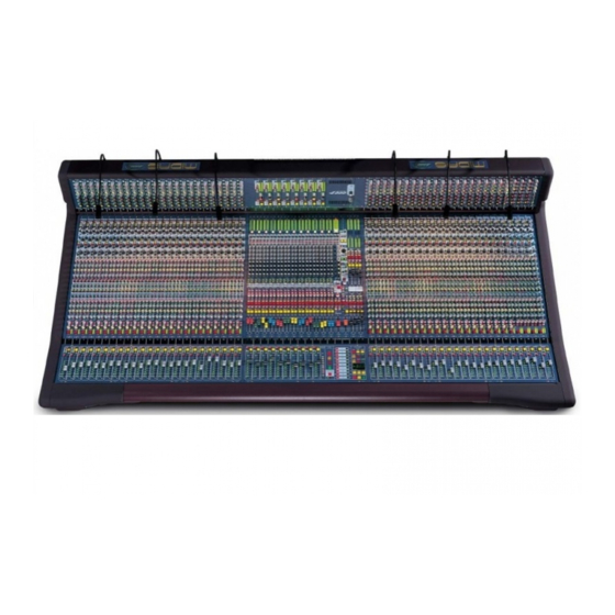
MIDAS Heritage 2000
Operators Manual
DOC02-H2000
Issue 1.4 - July 2002
Due to a policy of continual product improvement, specification
and features
may be subject to change without notice.
Advertisement
Table of Contents

Related Manuals for Midas HERITAGE 2000


Summary of Contents for Midas HERITAGE 2000
- Page 1 DY11 7HJ. England. Tel:+44 1562 741515 Fax:+44 1562 745371 Email: midas.info@uk.telex.com Website: midasconsoles.com MIDAS Heritage 2000 Operators Manual DOC02-H2000 Issue 1.4 - July 2002 Due to a policy of continual product improvement, specification and features may be subject to change without notice.
- Page 3 CAUTION RISK OF ELECTRIC SHOCK DO NOT OPEN WARNING: TO REDUCE THE RISK OF FIRE OR ELECTRIC SHOCK, DO NOT EXPOSE THIS APPLIANCE TO RAIN OR MOISTURE AVIS: RISQUE DE CHOC ELECTRIQUE. NE PAS OUVRIR These symbols are internationally accepted symbols that warn of potential hazards with electrical products.
- Page 5 Declare that a sample of the following product:- Product Type Number Product Description Nominal Voltage (s) Current Freq Heritage 2000 Audio Mixing Desk 115V AC 50/60Hz and dual redundant PSUs 230V AC to which this declaration refers, is in conformity with the following directives and/or standards:-...
- Page 7 ATTENTION! The following special limitations apply to the console and must be observed in order to maintain safety and electromagnetic compatibility performance: POWER CONNECTION The console should only be operated with the power supply connected to ground via its mains supply connector. CONTROL CONNECTIONS The console should only be operated with high quality screened control cables.
- Page 9 CONNECTORS MIDI In MIDI Pin 2: Ground Pin 4: In+ Pin 5: In- Input / Output XLR MIDI Thru Pin 1: Ground Pin 2: Ground Pin 2: Hot Pin 4: In+ Pin 3: Cold Pin 5: In- MIDI Out Pin 2: Ground Pin 4: In+ Pin 5: In- Midas Can Bus...
-
Page 11: Table Of Contents
Contents Midas HS0002 Mono Input Module Page 1 Midas HS0003 Input Fader Page 6 Midas HS0005 Stereo Input Module Page 8 Midas HS0003 Input Fader Page 13 Midas HS0012 Group Module Page 15 Midas HS0013 VCA Master Fader Page 19 Midas HS0051 Aux Module Page 21 Midas HS0021 Master Module... -
Page 13: Mono Input
MIDAS HS0002 gain Mono Input direct o/p freq Module bell treble freq hi-mid lo-mid freq bell bass freq freq aux 1 aux 2 aux 3 aux 4 aux 5 aux 6 aux 7 aux 8 9 - 10 level MONO 11 - 12 level MONO... - Page 14 The 48V switch connects 48 volt phantom power to the input connector which is suitable for a condenser microphone or DI box. The PAD switch gives 25dB of The GAIN control gives continuous attenuation to the input signal which will adjustment of the input amplifier allow the connection of high output gain from + 15dB to + 60dB.
- Page 15 The LO MID (dual concentric top) control gives continuous adjustment of boost and cut from + 15dB to - 15dB with a 0dB centre detent. The lo mid FREQ control gives continuous adjustment of the frequency The lo mid WIDTH (dual concentric range that the lo mid equaliser acts on bottom) control gives continuous from 100Hz to 2k.
- Page 16 The mono AUX controls (1 to 8) give continuous adjustment of the level sent from the input channel to the aux busses. The level adjustment is from aux 1 + 6dB to off. aux 2 aux 3 aux 4 The mono aux ON switches connect signals from the input channel to the mono aux busses.
- Page 17 The PAN defaults to control the channel placement within a group or master The ST switch connects the post fader stereo mix and has a constant power law channel signal to the master stereo bus i.e. - 3dB at the centre position. via the pan control.
-
Page 18: Midas Hs0003 Input Fader
MIDAS HS0003 Input Fader safe’s safe’s safe’s safe’s safe’s safe’s safe’s safe’s MUTE MUTE MUTE MUTE MUTE MUTE MUTE MUTE solo solo solo solo solo solo solo solo AUTO AUTO AUTO AUTO AUTO AUTO AUTO AUTO MIDAS MIDAS HS0003... - Page 19 The SOLO switch sends the input channel The SAFE switches disable remote signal to the PFL mono and AFL stereo control of the channels as follows:- busses. If the switch is pressed for a short time it will latch on or off, but if it is held i.
-
Page 20: Stereo Input
MIDAS HS0005 gain Stereo Input balance freq Module bell treble freq hi-mid lo-mid freq bell bass freq freq aux 1 aux 2 aux 3 aux 4 aux 5 aux 6 aux 7 aux 8 9 - 10 level MONO 11 - 12 level MONO group... - Page 21 The 48V switch connects 48 volt phantom power to both input connectors and is suitable for condenser microphones or DI boxes. The PAD switch gives 25dB of attenuation in both input signals to allow The GAIN control gives continuous the connection of high output adjustment of the input amplifier gains microphones or line level signals.
- Page 22 The LO MID control gives continuous adjustment of left and right boost and cut from +15dB to -15dB with a 0dB centre detent. The lo mid FREQ control gives continuous adjustment of the frequency range that the lo mid equalisers act on The lo mid HI Q control changes the from 100Hz to 2k.
- Page 23 The mono AUX controls (1 to 8) give continuous adjustment of the level sent from the input channel to the aux busses. The signal is a mono sum of the left and right aux 1 signals and the level adjustment is from The mono aux ON switches connect + 6dB to off.
- Page 24 The left and right PAN controls are used to place the input channel signals within a stereo group or stereo master mix. As well as image placement, the controls can also adjust the image width from stereo through mono to reverse stereo (left and right crossed over).
- Page 25 MIDAS HS0003 Input Fader safe’s safe’s safe’s safe’s safe’s safe’s safe’s safe’s MUTE MUTE MUTE MUTE MUTE MUTE MUTE MUTE solo solo solo solo solo solo solo solo AUTO AUTO AUTO AUTO AUTO AUTO AUTO AUTO MIDAS MIDAS HS0003...
- Page 26 The SOLO switch sends the input channel The SAFE switches disable remote signal to the PFL mono and AFL stereo control of the channels as follows:- busses. If the switch is pressed for a short time it will latch on or off, but if it is held i.
- Page 27 +21+ +18+ +15+ +12+ MIDAS HS0012 -12- -15- -18- -21- -24- -27- Group Module -30- -33- -36- direct inputs level level insert insert MUTE MUTE SOLO SOLO matrix fader fader insert insert to masters MONO MONO TALK TALK mute mute SAFE SAFE split...
- Page 28 +21+ +18+ +15+ +12+ The METERS monitor the peak signal levels of the sub group outputs -12- -15- (post fader). -18- -21- -24- -27- -30- -33- -36- The direct SOLO switches send direct inputs to the PFL mono and AFL the stereo busses (AFL is selected as stereo or mono depending on the group SPLIT switch settings).
- Page 29 The matrix MIX controls (1 to 8) give continuous adjustment of the sub group levels sent to the matrix mixes from + 6dB to off. The PRE fader switches change the signals sent to the matrix mixes from post matrix group fader to pre group fader.
- Page 30 to masters The ST switches connect the post fader sub group signals to the stereo master stereo busses via the pan controls. The MONO switches connect the post MONO MONO fader sub group signals to the mono master bus. The group PAN controls place the sub groups within the stereo master mix and have a constant power law i.e.
- Page 31 MIDAS HS0013 VCA Master Fader MUTE MUTE MUTE MUTE MUTE MUTE MUTE MUTE MUTE MUTE safe safe safe safe safe safe safe safe safe safe solo solo solo solo solo solo solo solo solo solo AUTO AUTO AUTO AUTO AUTO AUTO AUTO AUTO...
- Page 32 The vca MUTE switches act on any post fader input channels or audio sub groups which are assigned to be controlled from the corresponding VCA masters. The switches can be controlled from snapshot The vca SOLO switches are used to MUTE automation.
-
Page 33: Aux Module
+21+ +18+ +15+ +12+ MIDAS HS0051 -12- -15- -18- -21- -24- -27- MIDAS HS0052 -30- -33- -36- MIDAS HS0053 +21+ +18+ +15+ +12+ Aux Module -12- -15- -18- -21- -24- -27- -30- -33- -36- TALK TALK mute mute SAFE SAFE split SOLO solo... - Page 34 +21+ +18+ +15+ +12+ The METERS monitor the peak signal levels of the aux outputs (post fader). -12- -15- -18- -21- -24- -27- -30- -33- -36- +21+ +18+ +15+ +12+ -12- -15- -18- -21- -24- -27- -30- -33- -36-...
- Page 35 The VCA switches assign the aux output to VCA control from VCA masters 9 The TALK switches connect the aux and 10. mixes to the MONITOR module. When the TALK INTERNAL or GENERATOR INTERNAL are active TALK TALK on the MONITOR module the oscillator, pink noise and talk mic can The INS switches connect the aux insert be routed into the aux mixes.
- Page 36 +21+ +21+ +18+ +18+ +15+ +15+ +12+ +12+ MIDAS HS0021 -12- -12- -15- -15- -18- -18- -21- -21- -24- -24- -27- -27- Masters Module -30- -30- -33- -33- -36- -36- direct inputs level level insert insert MUTE MUTE SOLO SOLO left right left...
- Page 37 +21+ +21+ +18+ +18+ +15+ +15+ +12+ +12+ The METERS monitor the peak signal levels of the three master outputs (post fader). -12- -12- The SOLO IN PLACE switch sets the -15- -15- console to solo in place mode. In this -18- -18- -21-...
- Page 38 left right left right left right The matrix MIX controls (1 to 8) give continuous adjustment of the master The matrix STEREO switches select the left levels sent to the matrix mixes from source for the lower matrix mix controls + 6dB to off.
- Page 39 The BALANCE (pan) control gives balance continuous and reciprocal adjustment of the stereo left and right signal levels by + 3dB to off. This allows fine adjustment of the left, right power levels and imaging. The TALK switches connect the stereo masters to the MONITOR module.
- Page 40 +21+ +18+ +15+ +12+ MIDAS HS0031 -12- -15- -18- -21- -24- -27- Monitor Module -30- -33- -36- 1kHz freq signal generator PINK level generator generator internal external to all TALK internal talk mic +20 +60 mic gain level talk talk internal external meter...
- Page 41 +21+ +18+ +15+ +12+ The METERS monitor the peak signal levels of the stereo left and right monitor paths. -12- -15- -18- -21- -24- -27- -30- -33- -36- The 1kHz switch overrides the swept frequency control giving a fixed 1k tone. The FREQ.
-
Page 42: Talk Mic
talk mic The TALK XLR socket accepts balanced 150 microphone signals. The MIC GAIN preset gives continuous adjustment of the microphone amplifier The talk LEVEL gives continuous gain from +20dB to +60dB and operates adjustment of the post limiter signals in conjunction with a peak limiter which from +10dB to off. - Page 43 The stereo output "b" C/O switch stereo output disconnects the stereo local monitor The MONO sum switch adds the left and outputs from the main "a" outputs and output ‘b’ right monitor signals with a 4.5dB re-routes them to the secondary "b" summing loss.
- Page 44 +21+ +18+ +15+ +12+ MIDAS HS0041 -12- -15- -18- -21- -24- -27- Matrix Module -30- -33- -36- +21+ +18+ +15+ +12+ -12- -15- -18- -21- -24- -27- -30- -33- -36- masters control TALK TALK mute mute SAFE SAFE split SOLO solo solo masters...
- Page 45 +21+ +18+ +15+ +12+ The METERS monitor the peak signal -12- levels of the matrix outputs (post fader). -15- -18- -21- -24- -27- -30- -33- -36- +21+ +18+ +15+ +12+ -12- -15- -18- -21- -24- -27- -30- -33- -36-...
- Page 46 masters control The VCA switches assign the matrix outputs to VCA control from the The TALK switches connect the matrix MASTER module fader. mixes to the MONITOR module. When the TALK INTERNAL or GENERATOR TALK TALK INTERNAL are active on the MONITOR module the oscillator, pink noise and talk The INS switches connect the matrix mic can be routed into the matrix mixes.
- Page 47 Automation mode automation assign system keys switches system store midi lock insert delete copy check cancel confirm mute fader scene act/scene down virtual fader recall mode last next MIDAS...
-
Page 48: Assignment Control
Assignment Control The LOCK switch will toggle state each time it is pressed. When the LOCK switch is illuminated all assignment changes are disabled and virtual fader operation is locked (either on or off). The console will automatically revert to a locked state if no assignment controls are operated within a 90 second period. -
Page 49: Snapshot Automation System
Snapshot Automation System Snapshots can be stored in the automation system as ACTs or SCENEs. There is no difference between an ACT or a SCENE apart from the numbering; scenes are just sub sets within acts. The AUTO MUTE GROUP MASTER switches (1 to 10) activate the mute circuits on any, mute group assigned, input channels. - Page 50 The SYSTEM switch gives the operator access to the system menu. Navigation of the menu is achieved by using the UP/DOWN switches to select an entry and then pressing CONFIRM to execute the selected function or sub menu. To exit a menu or sub menu press CANCEL. The system menu contains LOCK which defines the level of console operation.
- Page 51 Fader Automation System The fader automation operates in two main ways:- REAL FADER MODE and VIRTUAL FADER MODE. In REAL FADER MODE all of the internal VCA systems are controlled safe’s by the real (physical) faders. The automation system can assist in the control of the real faders by prompting the operator using the 11 LED's MUTE next to each fader.
- Page 52 The differences between virtual fader recall and store are explained in more detail in the chart below:- Recall Mode Store Mode Recall a new scene and leds will indicate Recall a new scene and leds will indicate the current virtual fader positions. Note that the current virtual fader positions.
- Page 53 It is possible to “pick up” all the faders and If faders are not cleared prior to recalling a then set them to 0dB if adjustment is not new scene it may be advisable to clear required. There is no need to “clear” them. them immediately afterwards to avoid This is a user preference.
- Page 54 As you can see from the previous two pages there are many different ways to control faders within the console. There is no right or wrong way and the best method will depend largely on the specific application and the user preference.
- Page 55 Heritage Menu Overview Ver 2.06 (Key this symbol denotes a CONFIRM button press ) SYSTEM LOCK TOTL All automation and assignment functions are disabled. MENU A-LK Only Assignment functions are available RCAL Only recall and assignment functions are available. STOR Scene storage, editing, recall and assignment operation available.
- Page 56 Store Menu If storing new scene When storing a new scene there are no options available, the scene will be stored with the fastest cross fade speed and the display will revert back to default. Store Menu When Overstoring When Overstoring an existing scene the following options are available. OVERSTORE OVR/STOR The scene is over stored and display reverts back to scene number...
- Page 57 Unlocking the Console: To unlock the mixing console press the SYSTEM menu button. Using the up/down keys scroll through the menu until LOCK is displayed, press CONFIRM. Using the up/down keys scroll through the menu until the desired level of unlock is displayed on the screen, then press the confirm button. Locking the Console: To lock the mixing console press the SYSTEM menu button.
- Page 58 Storing a Scene Cont. Selecting a memory number and storing the memory: a/ The numbers in the display can be altered as follows. Select either Act or Scene using the ACT/SCENE C/O switch. You will see either act or scene illuminate below the display.
- Page 59 Editing the Cross fade Value of a Scene: a/ Recall the scene you wish to copy by selecting the scene number and pressing the NOW button. b/ Press the STORE button, and using the UP and DOWN buttons scroll through the display until XFADE is shown, press CONFIRM.
- Page 60 Midi In Assignment: Setting The Console to Respond to MIDI Changes: The console settings can be accessed via the “AUTO” submenu after pressing the “System” button. This submenu option is only available when in “SYS” Lock-Mode. After selecting “AUTO”, there are two further sub-menus: 1.
- Page 61 MIDI “NOTE” to numerical value lookup table OCTAVE NOTE 12 24 36 48 60 72 84 96 108 120 13 25 37 49 61 73 85 97 109 121 14 26 38 50 62 74 86 98 110 122 15 27 39 51 63 75 87 99 111 123 16 28 40 52 64 76 88 00 112 124 5 17 29 41 53 65 77 89 01 113 125...
- Page 62 Linking Heritage Consoles together Via CAN: A maximum of 6 consoles can be linked via the CAN bus connector located at the rear of the Heritage consoles. Any mixture of any Heritage consoles may be linked H3000,H2000 or H1000.. They are linked using a cable the description of which is given on the next page. If you have more than 2 consoles in a system the end consoles(either end of the cable) must have the RED termination button in the out position (default), all other consoles must have this Red button pressed in.
-
Page 63: Midas Can Bus
Midas Can Bus Cable... - Page 66 Rear Panel Left View Rear Panel Centre View Rear Panel Right View...
- Page 67 Heritage 2000 Frame Measurements 41.5” 1054mm Configuration data 24 channel 20 mono/4 stereo 133kg 293.2lbs 1054mm x 1441mm 41.49” x 59.73” 32 channel 28 mono/4 stereo 155kg 341.7lbs 1054mm x 1713mm 41.49” x 67.44” 40 channel 36 mono/4 stereo 173kg 381.4lbs 1054mm x 1985mm 41.49”...
- Page 69 SCENE PREVIEW...
-
Page 71: Matrix Module
+21+ +21+ HERITAGE 2000 MATRIX MODULE +18+ +18+ +15+ +15+ +12+ +12+ BLOCK DIAGRAM ISSUE A DATE 1 - 5 - 98 -12- -12- -15- -15- -18- -18- -21- -21- -24- -24- METERS PRE -27- -27- TALK -30- -30- SELECTED... -
Page 72: Aux Module
+21+ +21+ HERITAGE 2000 AUX MODULE +18+ +18+ +15+ +15+ +12+ +12+ BLOCK DIAGRAM ISSUE A DATE 1 - 5 - 98 -12- -12- -15- -15- -18- -18- -21- -21- -24- -24- METERS PRE -27- -27- TALK -30- -30- SELECTED... -
Page 75: Master Module
Heritage 2000 Specification Overview and Statistics. 1. The 2000 is a 30 buss console with an additional 15 x 8 output matrix. The busses are as follows:- 12 audio groups = 24 8 mono aux 2 stereo aux 1 stereo master... - Page 76 7. The 2000 has 58 long throw faders for mix control with fader position recall and virtual fader functions. 8. The 2000 has a total of 1043 automated switch functions as follows:- 480 input channel VCA sub group virtual assign switches 480 input channel mute sub group virtual assign switches 48 input channel mute switches 12 audio sub group mute switches...
- Page 77 Heritage 2000 Technical Specifications. Input Impedance 2k Balanced Line 20k Balanced Input Gain Continuously variable from (all faders at 0dB) + 15dB to + 60dB Mic + Pad Continuously variable from - 10dB to + 35dB Line Level Inputs Maximum Input Level...
- Page 78 Output Impedance All Line Outputs 50 Ohms Balanced Source to drive > 600 Headphones To drive > 8 Maximum Output Level All Line Outputs + 21dBu Headphones + 21dBu Nominal Signal Level - 60dBu to + 10dBu Line 0dBu Headphones + 10dBu Equaliser Hi pass Slope...
- Page 79 Bass Gain Continuously variable + 15 dB to - 15 dB Centre detent = 0dB Bass Shelving Freq. Continuously variable - 3dB point from 20Hz to 400Hz Bass Bell Freq. Continuously variable centre from 20Hz to 400Hz Bass Bell Bandwidth Continuously variable 0.1 Oct.
- Page 81 Input Crib Sheet Inputs Notes:...
Need help?
Do you have a question about the HERITAGE 2000 and is the answer not in the manual?
Questions and answers