
Related Manuals for Opticon OPV 1001


Summary of Contents for Opticon OPV 1001
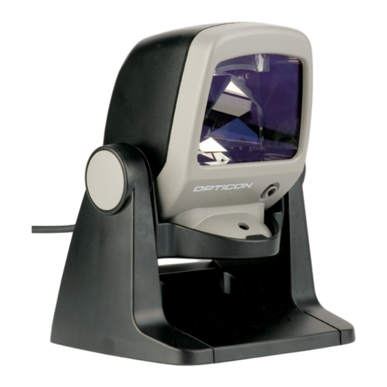
- Page 1 Laser Multi-barcode Scanner OPV 1001 The OPV 1001 is a 1000 scans multi-barcode laser Specifications Manual scanner reading for omni-directional reading.
-
Page 2: Serial Number
Unless otherwise agreed in a written contract, all Opticon products are warranted against defects in materials and workmanship for two years after purchase. Opticon will repair or, at its option, replace products that are defective in materials or workmanship with proper use during the warranty period. Opticon is not liable for damages caused by modifications made by a customer. -
Page 3: Table Of Contents
Opticon OPV 1001 Specifications Manual Contents 1. Abstract ............................7 2. Overview............................7 3. Physical Features ........................8 3.1. Dimensions ......................... 8 3.2. Weight ..........................8 4. Environmental Specifications ....................8 4.1. Operating Temperature and Humidity ................. 8 4.2. Storage Temperature and Humidity ..................8 4.3. - Page 4 Opticon OPV 1001 Specifications Manual 8.1.3. Pin Assignment ........................16 8.1.4. Interface Circuit........................17 8.1.5. Character Format........................17 8.1.6. Communication Format......................17 8.1.7. Handshaking ..........................18 8.2. USB Interface Specifications..................... 23 8.2.1. Connector..........................23 8.2.2. Interface Circuit........................23 8.3. DOS/V Wedge Interface Specification ................24 8.3.1. Connectors..........................24 9.
- Page 5 19.2. Temperature Conditions....................43 19.3. Foreign Materials ......................43 19.4. Other ..........................43 20. Mechanical Drawing ......................... 44 20.1. OPV 1001 (without stand) ....................44 20.2. OPV 1001 (with stand) ...................... 44 Table of Figures Figure 1: Scan area ........................11 Figure 2: Depth of field .......................
- Page 6 Opticon OPV 1001 Specifications Manual Figure 14: Handshaking: Modem mode ..................20 Figure 15: Handshaking: ACK/NAK .................... 21 Figure 16: Handshaking: ACK/NAK—No response ..............22 Figure 17: USB "A" connector ....................23 Figure 18: Interface circuit (USB) ....................23 Figure 19: Wedge connector (host side)..................24 Figure 20: Wedge connector (keyboard side)................
-
Page 7: Abstract
This manual provides specifications for the OPV 1001 laser multi-barcode scanner. 2. Overview The OPV 1001 outputs laser beams in multiple directions (4 lines each in 5 directions) to scan barcodes. For non-contact scanning, a barcode needs to face the scan window of the OPV 1001. -
Page 8: Physical Features
3. Physical Features 3.1. Dimensions (Without stand) W 71.0 x D 79.4 x H 100.0 mm 3.2. Weight OPV 1001: 200 g (max.) excluding the cable Stand: 340 g (max.) 4. Environmental Specifications 4.1. Operating Temperature and Humidity Temperature: 0 to +40° C Humidity: 20 to 90% RH 4.2. -
Page 9: Electrical Specifications
Opticon OPV 1001 Specifications Manual 5. Electrical Specifications 5.1. Power Supply Input voltage DC 5 V ±5 % (6 V also supported) Power ripple up to 100 mVp-p (10 Hz to 100 kHz DC 5V) Current consumption up to 500 mA Conditions: •... -
Page 10: Optical Specifications
Opticon OPV 1001 Specifications Manual 6. Optical Specifications 6.1. Laser Scan Specifications Parameter Specification Unit Light-emitting element Red laser diode – Emission wavelength 650 ±10 (25° C) Light output 1.0 or less (measured at the front of the scanner’s plastic mask) -
Page 11: Scan Area And Resolution
Opticon OPV 1001 Specifications Manual 7.3. Scan Area and Resolution Scan Area 7.3.1. The scannable area depends on the barcode type (PCS, resolution, length, etc.) and the direction of the barcode surface. However, the barcode should be set within the following area. -
Page 12: Figure 2: Depth Of Field
Opticon OPV 1001 Specifications Manual Figure 2: Depth of field Resolution Decode Depth (mm) (mm) 0.66 70 - 230 0.33 15 - 200 0.9 or higher 15 - 110 0.127 15 - 50 Resolution Symbology Digit Barcode Sample (mm) 0.66... -
Page 13: Pitch, Skew, And Tilt
Opticon OPV 1001 Specifications Manual 7.4. Pitch, Skew, and Tilt Pitch Angle 7.4.1. α = ±35° Figure 3: Pitch Skew Angle and Dead Zone 7.4.2. Skew angle: β = ±50° (Excluding dead zone) Dead zone: β = ±8° (There are some areas in which decoding fails due to... -
Page 14: Tilt
Opticon OPV 1001 Specifications Manual Tilt 7.4.3. γ = 360° There are some angles at which decoding fails, depending on the height of a barcode. Figure 5: Tilt Conditions Barcode Sample: OPTOELECTRONICS Test Sample Distance: 70 mm from the front edge of the scanner... -
Page 15: Curvature
Opticon OPV 1001 Specifications Manual 7.5. Curvature With 8-digit JAN/UPC/EAN barcodes, decoding performance is guaranteed when R≥20 mm. With 13-digit JAN/UPC/EAN barcodes, decoding performance is guaranteed when R≥25 mm. Figure 6: Curvature Conditions Barcode Sample: OPTOELECTRONICS Test Sample PCS = 0.9, Resolution = 0.33 mm... -
Page 16: Interface Specifications
Opticon OPV 1001 Specifications Manual 8. Interface Specifications The interface type is determined automatically, depending on the cable type. 8.1. RS-232C Interface Settings and Communication 8.1.1. Item [U2] setting Baud rate 9600 bps Start/stop bits 1 bit Data bits 8 bits... -
Page 17: Interface Circuit
Opticon OPV 1001 Specifications Manual Interface Circuit 8.1.4. Figure 7: Interface circuit (RS-232C) Character Format 8.1.5. Figure 8: Character format (same for both sending and receiving) Communication Format 8.1.6. Figure 9: Communication format... -
Page 18: Handshaking
Opticon OPV 1001 Specifications Manual Handshaking 8.1.7. Select handshaking options using the menu or command listed below. Handshaking Menu/Command No handshake BUSY/READY MODEM ACK/NAK ACK/NAK NO RESPONSE a) No Handshaking The scanner attempts the communication regardless of the state of the host computer. -
Page 19: Figure 12: Handshaking Busy/Ready
Opticon OPV 1001 Specifications Manual is not ON within a specified period. The Flow Control time-outs are as follows, and the default setting is “indefinitely“ (I0). Flow Control Time Out Menu/Command Indefinitely 100 ms 200 ms 400 ms Figure 12: Handshaking Busy/Ready... -
Page 20: Figure 14: Handshaking: Modem Mode
Opticon OPV 1001 Specifications Manual c) MODEM The scanner turns RTS line ON before transmitting data. Other processes are the same as BUSY/READY. Figure 14: Handshaking: Modem mode... -
Page 21: Figure 15: Handshaking: Ack/Nak
Opticon OPV 1001 Specifications Manual d) ACK/NAK After data has been transmitted, the scanner expects to receive one of the following responses from the host: ACK response—Action: The scanner completes transmission with the good-read buzzer and returns to the initial state. -
Page 22: Figure 16: Handshaking: Ack/Nak-No Response
Opticon OPV 1001 Specifications Manual e) ACK/NAK NO RESPONSE When no response from the host is received within the setting time, the scanner assumes an ACK response, and returns to the initial state without the error buzzer. The other actions are the same as ACK/NAK. -
Page 23: Usb Interface Specifications
Opticon OPV 1001 Specifications Manual 8.2. USB Interface Specifications Connector 8.2.1. a) USB "A" connector Figure 17: USB "A" connector Contact Number Signal Name Notes Power signal -DATA +DATA Interface Circuit 8.2.2. Figure 18: Interface circuit (USB) -
Page 24: Dos/V Wedge Interface Specification
Opticon OPV 1001 Specifications Manual 8.3. DOS/V Wedge Interface Specification Connectors 8.3.1. a) DOS/V Host Side Figure 19: Wedge connector (host side) Contact Number Signal Name Notes CPU DATA KEY DATA Power signal CPU CLOCK KEY CLOCK b) DOS/V Keyboard Side... -
Page 25: Figure 21: Wedge Connector (Dos/V Side)
Opticon OPV 1001 Specifications Manual c) DOS/V Side Figure 21: Wedge connector (DOS/V side) Contact Number Signal Name Notes CPU DATA OPEN CPU CLOCK OPEN Note: To connect a PS2 port that supports both a mouse and a keyboard, please use the Y cable that is packaged with the scanner. -
Page 26: Cable And Connector
Opticon OPV 1001 Specifications Manual 9. Cable and Connector 9.1. Cables (Standard specification) Type: Straight (with power jack – RS-232C, DOS/V Wedge only) Diameter: φ3.8 mm (main cable), φ3 mm (AC adapter cable) Length: 2000 ±50 mm (excluding main cable and connector) 250 ±20 mm (excluding AC adapter cable and jack) -
Page 27: Dos V/Wedge Cable
Opticon OPV 1001 Specifications Manual DOS V/Wedge Cable 9.1.3. Figure 24: Wedge cable 9.2. Connectors RS-232C interface: D-Sub 9-pin (female) connector DOS/V Wedge interface: Mini-DIN 6-pin (female) connector USB interface: USB-A connector 10. Default Settings 10.1. Set Default Interface Scan the following menu barcodes to return to the default settings. - Page 28 Opticon OPV 1001 Specifications Manual USB-VCP Functions Menu labels Menu codes _ZZ_ USB-VCP _C0_ _ZZ_ Wedge (with keyboard) Functions Menu labels Menu codes _ZZ_ AT-Wedge _UB_ With keyboard _KM_ _ZZ_ Wedge (without keyboard) Functions Menu labels Menu codes _ZZ_ AT-Wedge...
-
Page 29: Default Settings 1: Readable Codes
Opticon OPV 1001 Specifications Manual 10.2. Default Settings 1: Readable Codes Symbology Read Transmit Transmit Calculate Other Code Prefix Suffix Length UPC-A - UPC-A Add-on - UPC-E - UPC-E Add-on - EAN-13 - EAN-13 Add-on - EAN-8 - EAN-8 Add-on -... -
Page 30: Default Settings 2: Read Options, Trigger, Buzzer
Opticon OPV 1001 Specifications Manual • In the “Transmit CD” column, “ ” means “Transmit check digit” and “X” means “Do not transmit check digit.” • In the “Calculate CD” column, “ ” means “Calculate check digit” and “X” means “Do not calculate check digit”. -
Page 31: Serial Number
Opticon OPV 1001 Specifications Manual 11. Serial Number The serial number shown below is affixed to the scanner. Figure 25: Serial number diagram... -
Page 32: Packaging Specifications
Opticon OPV 1001 Specifications Manual 12. Packaging Specifications Put the scanner in a protective foam bag and place it in an individual packing box with the accessories. Size of the package (after assembly): 165 (W) X 255 (D) X 150 (H) mm PR O TEC TI O N BAG G (... -
Page 33: Collective Packaging Specification
Opticon OPV 1001 Specifications Manual 12.2. Collective Packaging Specification Put 20 single packages into the packing box. Size of the package (after assembly): 530 (W) X 850 (D) X 325 (H) mm C om pl et e- set R o w s T h e o rd e r o f se ri a l -N o . -
Page 34: Durability
Opticon OPV 1001 Specifications Manual 13. Durability 13.1. Static Electricity Air discharge: ±8 kV max. (No malfunction) ±15 kV max. (No destruction) Contact discharge: ±4 kV max. (No malfunction) ±8 kV max. (No destruction) Measurement Use electrostatic testing device compliant with IEC 61000-4-2... -
Page 35: Cable Strength
Opticon OPV 1001 Specifications Manual 13.4. Cable Strength No malfunction occurred after the following cable strength test. Affix the scanner to an immovable object, then pull it using a force of 2.5 kgf for 1 second. Carry out this test 20 times. -
Page 36: Trigger And Read Options
Opticon OPV 1001 Specifications Manual 15. Trigger and Read Options The OPV 1001 has read and trigger settings as follows: 15.1. Trigger Modes • Disabled: When this option is selected, the reader will stay on all the time. • Enabled: After receiving a trigger signal, the barcode reader will turn on and the read cycle starts. -
Page 37: Trigger And Read Settings
Opticon OPV 1001 Specifications Manual Figure 30: Auto-trigger detection area 16. Trigger and Read Settings 16.1. Auto Trigger Enable/Disable Settings Use the following settings to enable or disable the auto trigger. (Auto trigger is disabled by default). To enable auto trigger, scan “ZZ”, “+I” and “ZZ” in that order. -
Page 38: Power Saving
Opticon OPV 1001 Specifications Manual 17. Power Saving The motor options are only applicable for selected laser bar code readers and with trigger enabled. If the read time is expired, the motor can be switched OFF. When the trigger is activated, the motor is switched ON again. -
Page 39: Power Saving 2 (Motor Rotation-1/2)
Opticon OPV 1001 Specifications Manual The enabled time for power saving can be set from 0 to 9999 seconds. Use the direct input numeric 0 to 4 digits after BBB to set the time. Example: 0 second “BBB” or “BBB” + “Q0”... -
Page 40: Figure 31: Menu Code Combinations (Part 1)
Opticon OPV 1001 Specifications Manual Figure 31: Menu code combinations (part 1) -
Page 41: Figure 32: Menu Code Combinations (Part 2)
Opticon OPV 1001 Specifications Manual Figure 32: Menu code combinations (part 2) -
Page 42: Regulatory Compliance
Opticon OPV 1001 Specifications Manual 18. Regulatory Compliance 18.1. Laser Safety The scanner emits laser beams. JIS C6802: 2005: Laser class 1 IEC 825-1/EN 60825-1: Laser class 1 FDA CDRH Laser class 1. Complies with 21 CFR 1040.10 and 1040.11 except for deviations pursuant to laser notice No. -
Page 43: Safety
Opticon OPV 1001 Specifications Manual 19. Safety Handle this product carefully. Do not deliberately subject it to any of the following. 19.1. Shock Do not throw or drop the scanner. Do not place heavy objects on the cables. 19.2. Temperature Conditions Do not use the scanner at temperatures outside the specified range. -
Page 44: Mechanical Drawing
Opticon OPV 1001 Specifications Manual 20. Mechanical Drawing 20.1. OPV 1001 (without stand) Figure 33: Mechanical drawing (without stand) 20.2. OPV 1001 (with stand) 1 0 0 1 1 2 Figure 34: Mechanical drawing(with stand)
Need help?
Do you have a question about the OPV 1001 and is the answer not in the manual?
Questions and answers