
Related Manuals for Opticon OPL 7836


Summary of Contents for Opticon OPL 7836
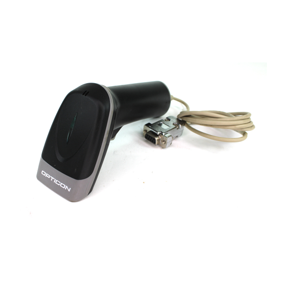
- Page 1 Handheld Laser Barcode Scanner OPL 7836 Specifications Manual The OPL 7836 is a handheld laser barcode scanner.
-
Page 2: Document History
Opticon assumes no liability for any direct, indirect, consequential or incidental damages arising out of use or inability to use both the hardware and software, even if Opticon has been informed about the possibility of such damages. -
Page 3: Table Of Contents
Opticon OPL 7836 Specifications Manual Contents 1. Abstract ............................7 2. Overview............................7 3. Physical Features ........................8 3.1. Dimensions ......................... 8 3.2. Weight ..........................8 4. Environmental Specifications ....................8 4.1. Operating Temperature and Humidity ................. 8 4.2. Storage Temperature and Humidity ..................8 4.3. - Page 4 Opticon OPL 7836 Specifications Manual 8.1.6. Communication Format......................17 8.1.7. Communication Control ......................18 8.2. USB Interface........................23 8.2.1. Settings ............................23 8.2.2. Interface Circuit........................23 8.3. DOS/V Wedge Interface....................23 8.3.1. Settings ............................23 9. Cable and Connector ....................... 24 9.1. RS-232C Cable ......................... 24 9.2.
- Page 5 Opticon OPL 7836 Specifications Manual 14. Reliability........................... 36 15. Trigger and Read Options ....................... 36 15.1. Auto Trigger Options ......................36 15.1.1. Auto Trigger Sensor.........................36 15.2. Auto Trigger Settings ......................37 15.2.1. Enable/Disable Settings......................37 16. Regulatory Compliance ......................38 16.1. Laser Safety ........................38 16.2.
- Page 6 Opticon OPL 7836 Specifications Manual Figure 21: WEDGE cable ......................26 Figure 22: Front view ........................26 Figure 23: Front view ........................27 Figure 24: Serial number diagram ....................32 Figure 25: Caution label ......................32 Figure 26: Drop test........................34 Figure 27: Cable bending test ....................
-
Page 7: Abstract
This manual provides specifications for the OPL 7836 barcode scanner. 2. Overview The OPL 7836 is a handheld laser barcode scanner. The OPL 7836 enhances visibility by using a short-wavelength red laser beam when scanning lines. Supported symbologies: Linear (1D) Postal JAN/UPC/EAN, incl. -
Page 8: Physical Features
Opticon OPL 7836 Specifications Manual 3. Physical Features 3.1. Dimensions W 144.5 x D 113.0 x H 54.3 (mm) 3.2. Weight 100 g max. (excluding cable) 4. Environmental Specifications 4.1. Operating Temperature and Humidity Temperature: -5 to +50° C Humidity: 20 to 85% RH 4.2. -
Page 9: Electrical Specifications
Opticon OPL 7836 Specifications Manual 5. Electrical Specifications 5.1. Electrical Characteristics Parameter Symbol Unit Remarks Power supply voltage Operating current Buzzer Off Rush current peak PEEK Stand-by current Startup time Conditions • Connect 1Ω resistance to a power supply line in series and measure the current by the voltage between both ends of resistance. -
Page 10: Curvature Of Scan
Opticon OPL 7836 Specifications Manual Curvature of Scan 6.1.2. Maximum gap between the straight line connecting both ends of the laser scan line and the actual laser scan line. Less than 1.27° curvature from the scan origin. Maximum of 3.3 mm when measured at the point 150 mm away from scan origin. -
Page 11: Scan Area And Resolution
Opticon OPL 7836 Specifications Manual 7.3. Scan Area and Resolution Depth of Field 7.3.1. The depth of field is measured from the edge of the scanner. The scanning range is within the circular arc centered on the scan origin. X direction: Depth of field Y direction: Laser scan widths within the depth of field Figure 2: The depth of a decoding field measured from the edge of the scanner. -
Page 12: Pitch, Skew, And Tilt
Opticon OPL 7836 Specifications Manual Resolution Symbology Quiet Zone Digit 1.0 mm Code 39 25 mm 0.5 mm Code 39 18 mm 0.25 mm Code 39 10 mm 0.15 mm Code 39 7 mm 0.127 Code 39 5 mm 7.4. Pitch, Skew, and Tilt Pitch Angle 7.4.1. -
Page 13: Skew Angle And Dead Zone
Opticon OPL 7836 Specifications Manual Skew Angle and Dead Zone 7.4.2. β = ±50° (Excluding dead zone) β = ±8° (There are some areas in which decoding fails due to specular reflection) Figure 4: Skew angle and dead zone... -
Page 14: Tilt Angle
Opticon OPL 7836 Specifications Manual Tilt Angle 7.4.3. γ = ±20° Figure 5: Tilt angle Conditions Barcode Sample: OPTOELECTRONICS Test Sample Distance: 90 mm from the front edge of the scanner Label: Pitch, Skew Angle, Dead Zone PCS = 0.9, Resolution = 0.25 mm, Symbology = 9-digit Code-39, N/W Ratio = 1:2.5... -
Page 15: Curvature
Opticon OPL 7836 Specifications Manual 7.5. Curvature With 8-digit JAN/UPC/EAN barcodes, decoding performance is guaranteed when R≥15 mm. With 13-digit JAN/UPC/EAN barcodes, decoding performance is guaranteed when R≥20 mm. Figure 6: Curvature Conditions Barcode Sample: OPTOELECTRONICS Test Sample PCS = 0.9, Resolution = 0.26 mm, Quiet Zone = 10 mm... -
Page 16: Interface Specifications
Opticon OPL 7836 Specifications Manual 8. Interface Specifications 8.1. RS-232C Interface Settings and Communication 8.1.1. Scan menu bar codes “ZZ” + “U2” + “ZZ” to initialize RS-232 interface. Item [U2] setting Baud rate 9600 BPS Start/stop bits 1 bit Data bits... -
Page 17: Interface Circuit
Opticon OPL 7836 Specifications Manual Interface Circuit 8.1.4. Host Computer ホスト Scanner 本機 F.GND DC INPUT Figure 7: Interface circuit Character Format 8.1.5. Figure 8:Character format (same for both sending and receiving) Communication Format 8.1.6. Figure 9: Communication format... -
Page 18: Communication Control
Opticon OPL 7836 Specifications Manual Communication Control 8.1.7. Select handshaking options using the menu or command listed below. Handshaking Menu/Command No handshake BUSY/READY MODEM ACK/NAK ACK/NAK NO RESPONSE a) No Handshaking The scanner attempts the communication regardless of the state of the host computer. -
Page 19: Figure 11: Busy/Ready Communication
Opticon OPL 7836 Specifications Manual b) BUSY/READY The scanner and the host computer notify each other of their state and whether they can receive data with BUSY/READY through an RTS line. They can communicate state to each other through a CTS line when connected as in the following figure. -
Page 20: Figure 13: Signal Timing
Opticon OPL 7836 Specifications Manual CTS, T×D signals timing When the CTS line (RTS signal of the host) is turned OFF while sending a T×D signal, the scanner transmits one character and waits. When the CTS signal is turned ON while transmitting a character, the character will be transmitted. -
Page 21: Figure 15: Ack/Nak
Opticon OPL 7836 Specifications Manual d) ACK/NAK After data has been transmitted, the scanner expects to receive one of the following responses from the host: • ACK response—Action: The scanner completes transmission with the good-read buzzer and returns to the initial state. -
Page 22: Figure 16: Ack/Nak-No Response
Opticon OPL 7836 Specifications Manual e) ACK/NAK NO RESPONSE When no response from the host is received within the setting time, the scanner assumes an ACK response, and returns to the initial state without the error buzzer. The other actions are the same as ACK/NAK. -
Page 23: Usb Interface
8.2. USB Interface Settings 8.2.1. Scan menu bar code “ZZ”+ “SU”+”ZZ” to set USB interface. The OPL 7836 utilizes a full-speed USB interface. Interface Circuit 8.2.2. Figure 17: Interface circuit Do not use the keyboard of the host during data transmission from the scanner to host. -
Page 24: Cable And Connector
Opticon OPL 7836 Specifications Manual 9. Cable and Connector 9.1. RS-232C Cable (Standard specification) Figure 18: RS-232C cable Type: Straight cable Diameter: φ3.8±0.5 mm Length: 1500±50 mm Cores: 6 insulated wires, 1 conductive wire Weight: Approximately 40 g 9.2. USB Cable... -
Page 25: Connector (Usb Interface)
Opticon OPL 7836 Specifications Manual Type: Straight cable Diameter: φ3.8±0.5 mm Length: 1500±100 mm Cores: 4 insulated wires, 1 conductive wire Weight: Approximately 40 g Connector (USB interface) 9.2.1. a) USB "A" connector Figure 20: USB "A" connector Contact Number... -
Page 26: Wedge Cable
Opticon OPL 7836 Specifications Manual 9.3. Wedge Cable (Standard specification) Figure 21: WEDGE cable Type: Y cable Diameter: φ3.8±0.5 mm Length: 1500±100 mm Cores: 6 insulated wires, 1 conductive wire Weight: Approximately 50 g Connector (Wedge interface) 9.3.1. a) DOS/V HOST Side... -
Page 27: Connector Specification (For Scanner)
Opticon OPL 7836 Specifications Manual CPU_CLK KEY_CLK b) DOS/V KEYBOARD Side Figure 23: Front view Contact Number Signal Name KEY_DATA OPEN KEY_CLK OPEN Do not use the keyboard of host during data transmission from the scanner to host. It may cause problems with the data transmission. -
Page 28: Default Settings
Opticon OPL 7836 Specifications Manual 10. Default Settings 10.1. Set Default Interface Scan the following menu barcodes to return to the default settings. RS-232C Functions Menu labels Menu codes _ZZ_ _U2_ RS-232C _ZZ_ USB-HID Functions Menu labels Menu codes _ZZ_... -
Page 29: Default Settings 1: Readable Codes
Opticon OPL 7836 Specifications Manual Wedge (without external keyboard) Functions Menu labels Menu codes _ZZ_ AT-Wedge _UB_ _KL_ Keyboard layout: without keyboard _ZZ_ 10.2. Default Settings 1: Readable Codes Symbology Read Transmit Transmit Calculate Other Code Prefix Suffix Length UPC-A —... - Page 30 Opticon OPL 7836 Specifications Manual Symbology Read Transmit Transmit Calculate Other Code Prefix Suffix Length Korean Postal — Code Matrix2of5 — MicroPDF417 — — — PDF417 — — — MSI/Plessey — S-Code — Telepen — Trioptic — — — Not transmit ST/SP UK/Plessey —...
-
Page 31: Default Settings 2: Read Options, Trigger, Buzzer
Opticon OPL 7836 Specifications Manual 10.3. Default Settings 2: Read Options, Trigger, Buzzer Item Default Setting Setting the number of characters Fixed length OFF all codes Read mode Single read Multiple read reset time 500 ms Add-on wait mode 500 ms... -
Page 32: Serial Number And Labeling
Opticon OPL 7836 Specifications Manual 11. Serial Number and Labeling The serial number is shown below is affixed to the scanner. Figure 24: Serial number diagram クラス1レーザ製品 JI S C 6802: 2005 I EC 60825- 1+A2: 2001 C LASS 1 LASER PR O D U C T Figure 25: Caution label 12. -
Page 33: Durability
Opticon OPL 7836 Specifications Manual 13. Durability 13.1. Electrical Noise No malfunction occurred when sinusoidal electrical noise (10 Hz–100 kHz, < 0.1 Vp-p) was added to the power supply line. Conditions Barcode Sample: OPTOELECTRONICS Test Sample Resolution 0.25 mm Symbology... -
Page 34: Shock
Opticon OPL 7836 Specifications Manual 13.3. Shock Drop Test (without packaging) 13.3.1. No malfunction occurred after the following drop test. Drop Test: Drop the scanner from a height of 1.5 m onto a concrete floor (once in each of 5 directions). Perform the test for three sets of five repetitions. -
Page 35: Dust And Drip Proof
Opticon OPL 7836 Specifications Manual 13.5. Dust and Drip Proof IEC IP x2 Water Prevention Level Details Vertically dripping water shall have no harmful effect when the enclosure is tilted at an angle up to 15° from its normal position. -
Page 36: Reliability
The estimate of MTBF and product life cycle is based on standard operation of the product within the recommended temperature range and without extreme electronic or mechanical shock. 15. Trigger and Read Options The OPL 7836 has read and trigger settings as follows: 15.1. Auto Trigger Options Auto Trigger Sensor 15.1.1. -
Page 37: Auto Trigger Settings
Opticon OPL 7836 Specifications Manual 15.2. Auto Trigger Settings Enable/Disable Settings 15.2.1. Use the following settings to enable or disable the auto trigger. (Auto trigger is disabled by default). To enable auto trigger, scan “ZZ”, “+I” and “ZZ” in that order. -
Page 38: Regulatory Compliance
Opticon OPL 7836 Specifications Manual 16. Regulatory Compliance 16.1. Laser Safety The scanner emits laser beams. JIS C6802: 2005: Laser class 2 IEC 825-1/EN 60825-1: Laser class 2 FDA CDRH Laser class II. Complies with 21 CFR 1040.10 and 1040.11 except for deviations pursuant to laser notice No. -
Page 39: Safety
Opticon OPL 7836 Specifications Manual 17. Safety Handle this product carefully. Do not deliberately subject it to any of the following. 17.1. Shock Do not throw or drop the scanner. Do not place heavy objects on the cables. 17.2. Temperature Conditions Do not use the scanner at temperatures outside the specified range. -
Page 40: Mechanical Drawing
Opticon OPL 7836 Specifications Manual 18. Mechanical Drawing Dimensions: 144.5 x 113.0 x 54.3 (excluding cable connection) Figure 28: Mechanical drawing...
Need help?
Do you have a question about the OPL 7836 and is the answer not in the manual?
Questions and answers