Table of Contents
Advertisement
Quick Links
Advertisement
Table of Contents

Related Manuals for Westermo Viper 3512 Series


Summary of Contents for Westermo Viper 3512 Series
- Page 1 Viper 3512 Series 12 port Ethernet M12 switches...
-
Page 2: Table Of Contents
6. Revision Notes ................24 Viper 3512 Series... -
Page 3: General Information
Westermo reserves the right to revise this document or withdraw it at any time without prior notice. -
Page 4: Safety And Regulations
No personal injury Minor damage to the order to avoid misuse of product the product, confusion or misunderstanding NOTICE Used for highlighting No personal injury Minor damage to the general, but important product information NOTE Table 1. Warning levels Viper 3512 Series... -
Page 5: Safety Information
(only valid for metallic housings). Westermo recommends a cross-sectional area of at least 4 mm Note that this product can be connected to two different power sources. -
Page 6: Electrostatic Discharge (Esd)
If the product is used in a manner not according to specification, the protection provided by the equipment may be impaired. If the product is not working properly, contact the place of purchase, the nearest Westermo distributor office or Westermo technical support. Viper 3512 Series... -
Page 7: Product Disposal
It needs to be handed over to an applicable collection point for recycling electrical and electronic equipment. Proper disposal of the product helps minimize hazardous substances and prevents potential negative impacts on both the environment and human health. Figure 1. WEEE symbol for treatment of product disposal Viper 3512 Series... -
Page 8: Compliance Information
This product has been tested and found to comply with the limits for a Class A digital device, pursuant to Part 15 of the FCC Rules. These limits are designed to provide reasonable protection against harmful interference when the product is operated in a commercial environment. Viper 3512 Series... -
Page 9: Simplified Declaration Of Conformity
2.5.4. Simplified Declaration of Conformity Hereby, Westermo declares that this product is in compliance with applicable EU directives and UK legislations. The full declaration of conformity and other detailed information is available at www.westermo.com/support/product-support. -
Page 10: Product Description
The backup device accessory matches the Viper in robustness and offers easy configuration update and backup. Meeting the requirements of the railcar market, the Viper 3512 series is very well suited for deployment in any other application with severe operating conditions and tough environments, for instance in the mining industry. -
Page 11: Hardware Overview
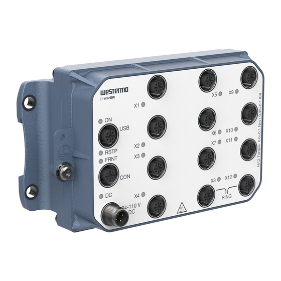
3.3. Hardware Overview RSTP FRNT 1000BA SE-T 24-110 V Description Description LED indicator 100 Mbps port Gbps port Power connection Console port Protective earth connection USB port Figure 3. Location of interface ports and LED indicators Viper 3512 Series... -
Page 12: Connector Pinout
Table 4. Power connector, male, A-coded Pin no. Signal Illustration No Connect. Do not connect. Table 5. Console connector, female, B-coded Pin no. Signal Illustration VBUS No Connect. Do not connect. Table 6. USB connector, female, A-coded Viper 3512 Series... - Page 13 Signal Illustration MDI, MDI-X and auto MDI/MDI-X modes are supported. The table shows signals in MDI mode. Table 7. 100 Mbps Ethernet connector, female, D-coded Pin no. Signal Illustration Table 8. Gbps connector, female, X-coded Viper 3512 Series...
-
Page 14: Led Indicators
Power OK on DC1 and DC2 Power failure on DC1 or DC2 X1 to No link GREEN Link established GREEN Data traffic indication FLASH YELLOW Port alarm, or port is set in blocking state by link redundancy protocol Table 9. LED indicators Viper 3512 Series... -
Page 15: Dimensions
3.6. Dimensions Dimensions are stated in mm. 164 ±0,5 Grounding point Screw M5x10 Figure 4. Dimensional drawing Viper 3512 Series... -
Page 16: Installation
RSTP FRNT 24-110 V RING Figure 5. Wall mounting 4.2. Protective Earth Connection For correct function, the earth connection needs to be properly connected to a designated PE rail. Torx: T25 and torque: 3.2 Nm. Viper 3512 Series... -
Page 17: Connection Of Cables
4.4. Cooling This product relies on convection cooling. Make sure that it is installed so that the ambient temperature is within the specified temperature range. Avoid obstruction of the airflow around the product. Viper 3512 Series... -
Page 18: Replacement Of Product
Cables [17]. For easy replication of the configuration of the original product, it is recommended to have the Westermo USB plug permanently connected to the USB port and move it over to the replacement product before it is powered up. -
Page 19: Specifications
To all other ports Circuit type Secondary circuit hazardous voltage, OVC II Connector 4-pin, male, M12, A-coded, recommended Westermo cables: 3146-1106 for 1.5 m, 3146-1107 for 5 m 3146-1107 for 5 m Cable size M12, recommended power cable area 0.5 mm² (minimum 0.25 mm²), which correlates to AWG 21 or larger... - Page 20 To all other ports Connector 8-pin, female, M12, X-coded Cabling Shielded cable CAT5e or better is recommended Conductive chassis FRNT reconfiguration Typically below 20 ms time Gbps ports are: X4, X8, X12 on Viper-3512(-E)-T3G-T9, X2-X4, X8, X12 on Viper-3512(-E)-T5G-T7 Viper 3512 Series...
- Page 21 200 mA Circuit type SELV Isolation To all Ethernet and DC ports No isolation to CON or protective earth Connector 5-pin, female, M12, A-coded, recommended Westermo USB plug 3641-0190 Console port Electrical specification RS-232 Data rate 115.2 kbit/s Data format...
-
Page 22: Type Tests And Environmental Conditions
Ethernet ports 2250 VDC, 1 min to all other ports Gbps Ethernet 2250 VDC, 1 min ports to all other ports 750 VDC after damp heat, according to EN 50155 Table 10. EMC and electrical conditions Viper 3512 Series... - Page 23 IEEE 1478 Class 1, condition E4. Indoor Refer to "Safety and Regulations" chapter regarding touch temperature Operational at +85°C for a limited time Installation and maintenance shall be made under controlled environments. Table 11. Environmental and mechanical conditions Viper 3512 Series...
-
Page 24: Revision Notes
6. Revision Notes Revision Date Change description Rev. A 2024-10 First version Viper 3512 Series... - Page 25 6641-22515 REV. A 2024 10 @ Westermo Network Technologies AB, Sweden...
Need help?
Do you have a question about the Viper 3512 Series and is the answer not in the manual?
Questions and answers