Table of Contents
Advertisement
Quick Links
Advertisement
Table of Contents

Related Manuals for Westermo PMI-110-F2G


Summary of Contents for Westermo PMI-110-F2G
- Page 1 PMI-110-F2G User’s Manual Version 3.0 Industrial Managed PoE Switch...
- Page 2 Copyright Notice Copyright 2019 Westermo Network Technologies AB All rights reserved. Reproduction in any form or by any means without permission is prohibited.
- Page 3 Federal Communications Commission (FCC) Statement This equipment has been tested and found to comply with the limits for a Class A digital device, pursuant to Part 15 of the FCC Rules. These limits are designed to provide reasonable protection against harmful interference when the equipment is operated in a commercial environment.
-
Page 4: Table Of Contents
Index Introduction .......................... 2 Overview ........................2 Major Features ......................6 Package List ......................8 Hardware Installation ......................9 Hardware Introduction ................... 10 Wiring Power Inputs ....................14 Wiring the Relay Output (DO)................16 Wiring the Digital Input (DI) ................. 17 Connecting the Surge /Lighting protection ............ - Page 5 Westermo Private MIB ..................234 Revision History ....................235...
-
Page 6: Introduction
1.3 Package Checklist Overview Westermo PMI-110-F2G is designed with eight 10/100TX PoE injector ports and two Gigabit RJ- 45 / SFP combo ports for highly critical PoE applications such as real time IP video surveillance, WiMAX systems and Wireless APs. All of the 8 ports of the switch are compliant with both IEEE 802.3af PoE and IEEE 802.3at high power PoE standards and can deliver up to 15.4W and 30W... - Page 7 PD function to obtain power through Ethernet cable eliminating the need of running separate power wirings to a remote device. The PMI-110-F2G is equipped with the new PSE solution, compliant with IEEE 802.3af, IEEE 802.3at 2-event or IEEE 802.3at 2- event plus LLDP standards, as well as forced mode powering mode for legacy Power over Ethernet cable devices.
- Page 8 PMI-110-F2G also supports advanced Ring technology – M.S.R. (Multiple Super Ring) which includes various new technologies for different network redundancy applications and structures. The supported MSR allows PMI-110-F2G aggregating up to 5 Rapid Super rings includes 4 Fast Ethernet plus 1 Gigabit Ethernet rings into one switch. With the MSR technology, a node can be configured to multiple rings with the failover time.
- Page 9 standbys by their link speed. The uplink with the highest speed is more likely to be active path for data transmission. Link aggregation is also integrated into RDH. An uplink connection can be a single link or several links aggregated as a trunk, which provides better redundancy and link capacity.
-
Page 10: Major Features
Outstanding Management and Enhanced Security The PMI-110-F2G provides various network control and security features to ensure the reliable and secure network connection. To optimize industrial network environment the switch supports advanced network features, such as Tag VLAN, IGMP Snooping, Quality of Service (QoS), Link Aggregation Control Protocol (LACP), Rate Control, etc. - Page 11 120W total power budget for High-power PoE camera SFP ports support 100/1000 Mbps with Digital Diagnostic Monitoring (DDM) to monitor long distance fiber quality All ports support 5ms recovery time, and MSR for up to 4 x 100M Rings plus 1 Gigabit ...
-
Page 12: Package List
Package List Westermo PMI-110-F2G is shipped with following items: PMI-110-F2G One DIN-Rail clip (attached to the switch) One RS-232 DB-9 to RJ-45 console cable Quick Installation Guide (QIG) If any of the above items is missing or damaged, please contact your local sales representative. -
Page 13: Hardware Installation
2 Hardware Installation This chapter includes hardware introduction, installation and configuration information. Following topics are covered in this chapter: 2.1 Hardware Introduction Dimension Panel Layout Bottom View Rear Side 2.2 Wiring Power Inputs 2.3 Wiring the Relay Output (DO) 2.4 Wiring the Digital Input (DI) 2.5 Connecting the Surge/ Lighting Protection 2.6 Wiring Ethernet Ports 2.7 Wall-mounting Installation... -
Page 14: Hardware Introduction
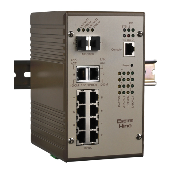
Hardware Introduction Dimension – PMI-110-F2G w/o DIN Rail mounting kit: 95(W) x 127 (D)x 160(H) PMI-110-F2G w/ DIN Rail mounting kit: 95(W) x 136.2 (D)x 160(H) - Page 15 Panel Layout The front panel includes 8 x 10/100Mbps RJ-45 PoE ports, 2 x Gigabit Ethernet RJ- 45/SFP socket ports, 1 RJ-45 for RS232 console, System diagnostic LEDs, Port LEDs, PoE status LEDs. Bottom view The bottom side includes 2 4-pin terminal block connectors and 1 chassis grounding screw.
- Page 16 for alarm relay output and digital input. Rear Side The rear side back panel attached DIN rail clip and one lighting screw to make connection with chassis ground and Switch inner lighting protection circuit. The product label is also sticked on the bottom side of DIN rail clip, in case if it is missed, please contact with your sales representive for product change.
- Page 17 This label indicates that the type of PoE is Type-2 high power PSE and performs PoE powering by Alternative-A mode (1,2,3,6)
-
Page 18: Wiring Power Inputs
Wiring Power Inputs The Power input port is located at the bottom side, and provides 2 power input connections in one 4-pin removable terminal block. The power port support polarity reverse protection; the Switch won’t start if wrong polarity applied. The wiring architecture please refers to below figure. -
Page 20: Wiring The Relay Output (Do)
Wiring the Relay Output (DO) The relay output contacts are in the bottom side as shown on below figure. The relay output (DO) is controlled by the pre-defined operating rules. To activate relay output function, please refer to the CD User’s Manual for more Relay Output management information. -
Page 21: Wiring The Digital Input (Di)
Wiring the Digital Input (DI) The Digital Input (D.I.) contacts are in the bottom side of the device as shown in below figure. It accepts one external DC type signal input and can be configured to send alert message through Ethernet when the signal is changed. The signal may trigger and generated by external power switch, like as door open trigger switch for control cabinet. -
Page 22: Connecting The Surge /Lighting Protection
Connecting the Surge /Lighting protection There is one screw fixed on the rear side for lighting /surge protection; tighten and wire to chassis grounding to obtain better surge/ lighting immunity. But, do remember remove the surge grounding screw before to insulation/Hi-pot testing. In case you do not, the protectors may damage during the testing, and the lighting protection will malfunction. - Page 23 Ethernet standard. Gigabit Ethernet /SFP combo port The PMI-110-F2G provides 2 Gigabit RJ-45/ SFP combo ports that with different link speed – 10Mbps, 100Mbps, 1000Mbps, and compliant with the standards of IEEE 802.3 10Base-T, IEEE 82.3u 100Base-TX, IEEE 8023.u 100Base-FX, IEEE 802.3ab 1000Base-T, and IEEE 802.3z Gigabit fiber.
-
Page 24: Din Rail Mounting Installation
This function is only available for Westermo recomended DDM SFP transceiver, and does not support third party transceiver that may not fully comply with MSA SFP transceiver standard. - Page 25 following includes the dimension of EN50022 DIN rail for your reference. The Switch should install and used at Restriced Acess Location area, like as the control room or control cabinet. Besides, the device’s surface temperature may caused damage while the Power over Ethernet function is enabled and under working, at the ambient temperature 70°C .
- Page 26 Check if DIN-Rail clip is tightly attached to the EN50022 Rail track. To remove PMI Switch from the track, reverse the steps above. Notes: 1. The DIN Rail should compliant with DIN EN50022 standard. Using wrong DIN rail may cause unsafe installation. 2.
-
Page 27: Preparation For Management
3.3 Preparation for Telnet console Preparation for Serial Console In the unit package, Westermo attached one RJ-45 to RS-232 DB-9 console cable. Please attach RS-232 DB-9 connector to your PC’s COM port, connect RJ- 45 connector to the Console port of the PMI PoE Managed Switch. If the serial cable is lost, please follow the serial console cable PIN assignment to find one. -
Page 28: Preparation For Web Interface
Web Interface for web management 3.2.1 Web Interface Westermo web management page is developed by CGI (Common Gateway Inerface). It allows you to use a standard web-browser such as Microsoft Internet Explorer, or Mozilla, to configure and interrogate the switch from anywhere on the network. - Page 29 Enter. 8. The login screen will appear next. 9. Key in user name and the password. Default user name is admin and password westermo. Click on Enter or OK. The Welcome page of the web-based management interface will then appear.
- Page 30 3.2.2 Secured Web Interface Westermo web management page also provides secured management HTTPS login. All the configuration commands will be secured and will be hard for the hackers to sniff the login password and configuration commands.
-
Page 31: Preparation For Telnet Console
Preparation for Telnet Console 3.3.1 Telnet Westermo PMI managed Switch supports Telnet console. You can connect to the switch by Telnet and the command lines are the same as what you see by RS232 console port. Below are the steps to open Telnet connection to the switch. - Page 32 Download PuTTY: http://www.chiark.greenend.org.uk/~sgtatham/putty/download.html The copyright of PuTTY 1. Open SSH Client/PuTTY In the Session configuration, enter the Host Name (IP Address of your PMI switch) and Port number (default = 22). Choose the “SSH” protocol. Then click on “Open” to start the SSH session console.
- Page 33 3. After few seconds, the SSH connection to Switch is opened. 4. Type the Login Name and its Password. The default Login Name and Password are admin / westermo. All the commands you see in SSH are the same as the CLI commands you see via RS232 console.
-
Page 34: Feature Configuration
IP address. Then you can remotely connect to its embedded HTML web pages or Telnet console. Westermo web management page is developed by CGI (Common Gateway Interface). It allows you to use a standard web-browser such as Microsoft Internet Explorer, or Mozilla, to configure and interrogate the switch from anywhere on the network. - Page 35 4.5 Network Redundancy 4.6 VLAN 4.7 Private VLAN 4.8 Traffic Prioritization 4.9 Multicast Filtering 4.10 SNMP 4.11 Security 4.12 Warning 4.13 Monitor and Diag 4.14 Device Front Panel 4.15 Save 4.16 Logout...
-
Page 36: Command Line Interface Introduction
Command Line Interface Introduction The Command Line Interface (CLI) is the user interface to the switch’s embedded software system. You can view the system information, show the status, configure the switch and receive a response back from the system by keying in a command. There are some different command modes. - Page 37 Privileged EXEC mode: Press enable in the User EXEC mode, then you can enter the Privileged EXEC mode. In this mode, the system allows you to view current configuration, reset default, reload switch, show system information, save configuration…and enter the global configuration mode.
- Page 38 Type configure terminal to enter next mode, exit to leave. ? to see the command Switch# archive Manage archive files clear Reset functions clock Configure time-of-day clock configure Configuration from vty interface copy Copy from one file to another debug Debugging functions (see also 'undebug') disable Turn off privileged mode command...
- Page 39 Global Configuration Mode: Press configure terminal in privileged EXEC mode. You can then enter global configuration mode. In global configuration mode, you can configure all the features that the system provides you. Type interface IFNAME/VLAN to enter interface configuration mode, exit to leave.
- Page 40 (Port) Interface Configuration: Press interface IFNAME in global configuration mode. You can then enter interface configuration mode. In this mode, you can configure port settings. The port interface name for fast Ethernet port 1 is fa1,… fast Ethernet 7 is fa7, fast Ethernet port 8 is fa8..
- Page 41 Available command lists of the global configuration mode. Switch(config)# interface fa1 Switch(config-if)# acceptable Configures the 802.1Q acceptable frame types of a port. auto-negotiation Enables auto-negotiation state of a given port description Interface specific description dot1x IEEE 802.1x standard access security control duplex Specifies the duplex mode of operation for a port End current mode and change to enable mode...
- Page 42 The VLAN interface name of VLAN 1 is VLAN 1, VLAN 2 is VLAN 2… Type exit to leave the mode. Type ? to see the available command list. The command lists of the VLAN interface configuration mode Switch(config)# interface vlan 1 Switch(config-if)# description Interface specific description End current mode and change to enable mode...
- Page 43 configuration…and enter global Type exit to logout configuration mode. Next Mode: Type configure terminal to enter global configuration command. Global In global configuration mode, you Enter: Type configure terminal in Switch(config)# configuration can configure all the features that privileged EXEC mode the system provides you Exit: Type exit or end or press Ctrl-Z to exit.
- Page 44 Here are some useful commands for you to see these available commands. Save your time in typing and avoid typing error. ? To see all the available commands in this mode. It helps you to see the next command you can/should type as well. Switch(config)# interface (?) IFNAME Interface's name vlan...
- Page 45 Alert message when multiple users want to configure the switch. If the administrator is in configuration mode, then the Web users can’t change the settings. PMI Managed Switch allows only one administrator to configure the switch at a time.
-
Page 46: Basic Setting
Basic Setting The Basic Setting group provides you to configure switch information, IP address and user name/Password of the system. It also allows you to do firmware upgrade, backup and restore configuration, reload factory default, and reboot the system. Following commands are included in this group: 4.2.1 Switch Setting 4.2.2 Admin Password 4.2.3 IP Configuration... - Page 47 System Name: You can assign a name to the device. The available characters you can input is 64. After you configure the name, CLI system will select the first 12 characters as the name in CLI system. System Location: You can specify the switch’s physical location here. The available characters you can input are 64.
- Page 48 4.2.2 Admin Password You can change the user name and the password here to enhance security Figure 4.2.2.1 Web UI sample...
- Page 49 New Password: You can key in new password here. The default setting is westermo. Confirm Password: You need to type the new password again to confirm it. Once you finish configuring the settings, click on Apply to apply your...
- Page 50 server Shared Key: It is the password for communicate between switch and Radius Server. Server Port: UDP port of Radius server. Primary TACACS+ Server The TACACS+ mechanisms are centralized “AAA” (Authentication, Authorization and Accounting) systems for connecting to network services. The fundamental purpose of TACACS+ is to provide an efficient and secure mechanism for user account management.
- Page 51 DHCP Client: You can select to Enable or Disable DHCP Client function. When DHCP Client function is enabled, an IP address will be assigned to the switch from the network’s DHCP server. In this mode, the default IP address will therefore be replaced by the one assigned by DHCP server.
- Page 52 Once you finish configuring the settings, click on Apply to apply your configuration. IPv6 Configuration –An IPv6 address is represented as eight groups of four hexadecimal digits, each group representing 16 bits (two octets). The groups are separated by colons (:), and the length of IPv6 address is 128bits. An example of an IPv6 address is: 2001:0db8:85a3:0000:0000:8a2e:0370:7334.
- Page 53 Prefix: the size of subnet or netwok, and it equivalent to the subnetmask, but written in different. The default subnet mask length is 64bits, and writen in decimal value - 64. Add: after add new IPv6 address and prefix, don’t forget click icon -“Add” to apply new address to system.
- Page 54 Manual Setting: User can select Manual setting to change time as user wants. User also can click the button “Get Time from PC” to get PC’s time setting for switch. NTP client: Select the Time Setting Source to NTP client can let device enable the NTP client service.
- Page 55 To enable IEEE 1588, select Enable in PTP Status and choose Auto, Master or Slave Mode. After time synchronized, the system time will display the correct time of the PTP server. Time-zone: Select the time zone where the switch is located. Following table lists the time zones for different locations for your reference.
- Page 56 18 (GMT-03:00) NewFoundland 19 (GMT-03:00) Brasilia 20 (GMT-03:00) Buenos Aires, Georgetown 21 (GMT-03:00) Greenland 22 (GMT-02:00) Mid-Atlantic 23 (GMT-01:00) Azores 24 (GMT-01:00) Cape Verde Is. 25 (GMT) Casablanca, Monrovia 26 (GMT) Greenwich Mean Time: Dublin, Edinburgh, Lisbon, London 27 (GMT+01:00) Amsterdam, Berlin, Bern, Rome, Stockholm, Vienna 28 (GMT+01:00) Belgrade, Bratislava, Budapest, Ljubljana, Prague 29 (GMT+01:00) Brussels, Copenhagen, Madrid, Paris 30 (GMT+01:00) Sarajevo, Skopje, Sofija, Vilnius, Warsaw, Zagreb...
- Page 57 50 (GMT+06:00) Almaty, Novosibirsk 51 (GMT+06:00) Astana, Dhaka 52 (GMT+06:00) Sri Jayawardenepura 53 (GMT+06:30) Rangoon 54 (GMT+07:00) Bangkok, Hanoi, Jakarta 55 (GMT+07:00) Krasnoyarsk 56 (GMT+08:00) Beijing, Chongqing, Hong Kong, Urumqi 57 (GMT+08:00) Irkutsk, Ulaan Bataar 58 (GMT+08:00) Kuala Lumpur, Singapore 59 (GMT+08:00) Perth 60 (GMT+08:00) Taipei 61 (GMT+09:00) Osaka, Sapporo, Tokyo...
- Page 58 Once you finish your configuration, click on Apply to activate your configuration. 4.2.5 DHCP Server You can select to Enable or Disable DHCP Server function. PMI switch will assign a new IP address to link partners. DHCP Server configuration After selecting to enable DHCP Server function, type in the Network IP address for the DHCP server IP pool, Subnet Mask, Default Gateway address and Lease Time for client.
- Page 59 Excluded Address: You can type a specific address into the IP Address field for the DHCP server reserved IP address. The IP address that is listed in the Excluded Address List Table will not be assigned to the network device. Add or remove an IP address from the Excluded Address List by clicking Add or Remove.
- Page 60 DHCP Leased Entries: PMI Switch provides an assigned IP address list for user check. It will show the MAC and IP address that was assigned by PMI Switch. Click the Reload button to refresh the listing. DHCP Relay Agent You can select to Enable or Disable DHCP relay agent function, and then select the modification type of option 82 field.
- Page 61 the field with prefered IP address of DHCP Server, and then click “Apply” to activate the DHCP relay agent function. All the DHCP packets from client will be modified by the policy and forwarded to DHCP server through the gateway port. Relay Policy Drop: Drops the option 82 field and do not add any option 82 field.
- Page 62 With Backup command, you can save current configuration file saved in the switch’s flash to admin PC or TFTP server. This will allow you to go to Restore command later to restore the configuration file back to the switch. Before you restore the configuration file, you must place the backup configuration file in the PC or TFTP server.
- Page 63 Note: point to the wrong file will cause the entire configuration missed 4.2.7 Firmware Upgrade In this section, you can update the latest firmware for your switch. Westermo provides the latest firmware in Westermo Web site. The new firmware may...
- Page 64 include new features, bug fixes or other software changes. We’ll also provide the release notes for the update as well. For technical viewpoint, we suggest you use the latest firmware before installing the switch to the customer site. Note that the system will be automatically rebooted after you finished upgrading new firmware.
- Page 65 TFTP: This section allows you to upload a firmware image that is stored on a TFTP server. IP: This is the IP address of the TFTP server where your firmware image is stored. File Name: This is the file name of the firmware image. Click Upgrade to begin upgrading the firmware.
- Page 66 Figure-4.2.8.1 The main screen of the Factory Default Figure 4.2.8.2 Popup alert screen to cnfirm the command. Click on Yes to start it Figure 4.2.8.3 Popup message screen to show you that have done the command. Click on OK to close the screen. Then please go to Reboot page to reboot the switch. Click on OK.
- Page 67 4.2.8 System Reboot System Reboot allows you to reboot the device. Some of the feature changes require you to reboot the system. Click on Reboot to reboot your device. Note: Remember to click on Save button to save your settings. Otherwise, the settings you made will be gone when the switch is powered off.
- Page 68 Switch(config)# hostname WORD Network name of this system Switch(config)# hostname “Switch” SWITCH(config)# System Location SWITCH(config)# snmp-server location Sweden System Contact SWITCH(config)# snmp-server contact support@westermo.se Display SWITCH# show snmp-server name SWITCH SWITCH# show snmp-server location Sweden SWITCH# show snmp-server contact support@westermo.se SWITCH>...
- Page 69 SWITCH(config)# administrator orwell orwell Change administrator account orwell and password orwell success. Display SWITCH# show administrator Administrator account information name: super password: super IP Configuration IP Address/Mask SWITCH(config)# int vlan 1 (192.168.2.8, SWITCH(config-if)# ip 255.255.255.0 address dhcp SWITCH(config-if)# ip address 192.168.2.8/24 SWITCH(config-if)# ip dhcp client SWITCH(config-if)# ip dhcp client renew Switch(config-if)# ipv6 address ;...
- Page 70 no shutdown ip route 0.0.0.0/0 192.168.2.254/24 Time Setting NTP Server SWITCH(config)# ntp peer enable disable primary secondary SWITCH(config)# ntp peer primary IPADDR SWITCH(config)# ntp peer primary 192.168.2.200 Time Zone SWITCH(config)# clock timezone 26 Sun Jan 1 04:13:24 2006 (GMT) Greenwich Mean Time: Dublin, Edinburgh, Lisbon, London Note: By typing clock timezone ?, you can see the timezone list.
- Page 71 Start week of month: 1~5 Start weekday: 0 (Sunday) ~6 (Saturday) Month: 1 (Jan) ~12 (Dec) IEEE 1588 Switch(config)# ptpd run <cr> preferred-clock Preferred Clock slave Run as slave Display SWITCH# sh ntp associations Network time protocol Status : Disabled Primary peer : N/A Secondary peer : N/A SWITCH# show clock...
- Page 72 Switch(config-dhcp)# service dhcp Configure DHCP network address pool Switch(config-dhcp)#network 50.50.50.0/4 -( network/mask) Switch(config-dhcp)#default-router 50.50.50.1 Lease time configure Switch(config-dhcp)#lease 300 (300 sec) DHCP Relay Agent Enable DHCP Relay Agent Switch# Switch# configure terminal Switch(config)# router dhcp Switch(config-dhcp)# service dhcp Switch(config-dhcp)# ip dhcp relay information option Enable DHCP Relay policy Switch(config-dhcp)# ip dhcp relay information policy replace drop...
- Page 73 Excluded Address List IP Address --------------- (list excluded address) Manual Binding List IP Address MAC Address --------------- -------------- (list IP & MAC binding entry) Leased Address List IP Address MAC Address Leased Time Remains --------------- -------------- -------------------- (list leased Time remain information for each entry) Backup and Restore Backup Startup Switch# copy startup-config tftp: 192.168.2.33/default.conf...
- Page 74 Configuration Show Running Switch# show running-config Configuration Firmware Upgrade Firmware Upgrade Switch# archive download-sw /overwrite tftp 192.168.2.33 pmi- 110.bin binary code file name Firmware upgrading, don't turn off the switch! Tftping file pmi-110.bin binary code file name Firmware upgrading ................
-
Page 75: Port Configuration
Port Configuration Port Configuration group enables you to enable/disable port state, or configure port auto-negotiation, speed, and duplex, flow control, rate limit control and port aggregation settings. It also allows you to view port status and aggregation information. Following commands are included in this group: 4.3.1 Port Control 4.3.2 Port Status 4.3.3 Rate Control... - Page 76 Select the port you want to configure and make changes to the port. In State column, you can enable or disable the state of this port. Once you disable, the port stop to link to the other end and stop to forward any traffic. The default setting is Enable which means all the ports are workable when you receive the device.
- Page 77 that corresponding port on the switch to work. “Disable” means that you don’t need to activate the flow control function of the remote network device, as the flow control of that corresponding port on the switch will work anyway. Description: the description of interface. It supports maximum characters length is 130.
- Page 78 The UI can display vendor name, wave length and distance of all Westermo SFP transceiver family. If you see Unknown info, it may mean that the vendor doesn’t provide their information or that the information of their transceiver can’t be read.
- Page 79 Rate limiting is a form of flow control used to enforce a strict bandwidth limit at a port. You can program separate transmit (Egress Rule) and receive (Ingress Rule) rate limits at each port, and even apply the limit to certain packet types as described below.
- Page 80 802.3ad. The aggregated ports can interconnect to the other switch which also supports Port Trunking. Westermo Supports 2 types of port trunking. One is Static Trunk, the other is 802.3ad. When the other end uses 802.3ad LACP, you should assign 802.3ad LACP to the trunk.
- Page 81 Aggregation Setting Trunk Size: The switch can support up to 8 trunk groups with 2 trunk members. Since the member ports should use same speed/duplex, max trunk members for 100Mbps would be 8, and 2 for gigabit. Group ID: Group ID is the ID for the port trunking group. Ports with same group ID are in the same group.
- Page 82 Aggregation Status This page shows the status of port aggregation. Once the aggregation ports are negotiated well, you will see following status Group ID: Display Trunk 1 to Trunk 5 set up in Aggregation Setting. Type: Static or LACP set up in Aggregation Setting. Aggregated: When LACP links well, you can see the member ports in aggregated column.
- Page 83 linked up will be displayed in the Link Down column. 4.3.5 Command Lines for Port Configuration Feature Command Line Port Control Port Control – State Switch(config-if)# shutdown -> Disable port state Port1 Link Change to DOWN interface fastethernet1 is shutdown now. Switch(config-if)# no shutdown ->...
- Page 84 Switch(config-if)# duplex full Port1 Link Change to DOWN set the duplex mode ok! Switch(config-if)# Port1 Link Change to UP Port Control – Flow Switch(config-if)# flowcontrol on Control Flowcontrol on for port 1 set ok! Switch(config-if)# flowcontrol off Flowcontrol off for port 1 set ok! Port Status Port Status Switch# show interface fa1...
- Page 85 STP Status: forwarding Default CoS Value for untagged packets is 0. Mdix mode is Disable. Medium mode is Copper. Note: Administrative Status -> Port state of the port. Operating status -> Current status of the port. Duplex -> Duplex mode of the port.
- Page 86 Rate Control - Switch(config-if)# rate-limit ingress bandwidth Bandwidth <0-100> Limit in magabits per second (0 is no limit) Switch(config-if)# rate-limit ingress bandwidth 8 Set the ingress rate limit 8Mbps for Port 1. Port Trunking LACP Switch(config)# lacp group 1 gi8-10 Group 1 based on LACP(802.3ad) is enabled! Note: The interface list is fa1,fa3-5,gi8-10 Note: different speed port can’t be aggregated together.
- Page 87 FLAGS: I -> Individual P -> In channel D -> Port Down Trunk Group GroupID Protocol Ports --------+---------+------------------------------------ LACP 8(D) 9(D) 10(D) Switch# show trunk group 2 FLAGS: I -> Individual P -> In channel D -> Port Down Trunk Group GroupID Protocol Ports --------+---------+------------------------------------ Static...
-
Page 88: Power Over Ethernet
Power over Ethernet Power over Ethernet is the key features of PMI PoE Switch. It is fully compliance with IEEE 802.3af and IEEE 802.3at that include 1-event with IEEE 802.1AB LLDP classification and 2-event classification mechanisms for PoE MDI. The PMI-110- F2G adapts 8-Port PoE injectors in port 1 to port 8, each port with the ability to deliver 30W to compatible IEEE 802.3at standard and provides 120w power budget for hall system. - Page 89 PoE System: enable or disable system’s PoE function. Budget (W): the power supply maximum output budget. Both power budget of DC 1 and DC2 will be aggregated. Voltage (V): the voltage of applied to the power input. Here, we suggest uses same specification of power supply.
- Page 90 PoE Mode:Enable/Diable port’s PoE function. Powering Mode: 802.3af, 802.3at(LLDP), 802.3at(2-event) and forced mode. Forced mode will ignore the classification behaviors and apply power onto the RJ- 45, uses the forced mode must be carefully. Power Budget(W): it allows user assigne the budget control in this field. Power priority: it supports 3 levels, Critical, High and low.
- Page 91 The PMI PoE Switch supports an useful function that help user to mainten the PD’s status and help use to savng the maintenance time and money. IP address: the PD’s ipaddress that installed on the port. Cycle time: user measured the PD system boots duration time. The unit is second.
- Page 92 Note: During the PoE operating, the surface will accumulate heat and caused surface temperature becomes higher than ambient temperature. Do remember don’t touch device surface during PoE operating. DO NOT TOUCH DEVICE SURFACE DURING PoE PROGRESS HIGH POWER FEEDING Note: To enable the IEEE 802.3at High Power PoE function, the power input voltage should be DC 52~57V to obtain better performance.
- Page 93 The Power over Ethernet schedule supports hourly and weekly base PoE schedule configuration. Selecte the target port and marking the time frame, then click Apply to activate the PoE scheduling function. The PoE port will working as the predefined behavior and follows the system clock.
- Page 94 4.4.4 Command Line for PoE control Syntax show poe system Parameters Command Mode Enable mode Description Display the status of the PoE system. Examples Switch> enable Switch# show poe system PoE System PoE Admin : Enable PoE Hardward : Normal PoE Input Voltage : 47.700 V Output power : 0.00 Watts Power Budget :...
- Page 95 Budget : 120 Watts Warning water level : N/A Utilization : 0 % Event : Normal Syntax show poe interface IFNAME Parameters IFNAME : interface name Command Mode Enable mode Description Display the PoE status of interface. Examples Switch> enable Switch# show poe interface fa1 Interface fastethernet1 (POE Port 1) Control Mode : User (Disable)
- Page 96 Command Mode Enable mode Description Display the status of pd status detection. Examples Switch# show poe pd-detect PD Status Detection Status : Enabled Host 1 : Target IP : 192.168.2.100 Cycle Time : 10 Host 2 : Target IP : 192.168.2.200 Cycle Time : 20 Host 3 : Target IP : 192.168.2.15...
- Page 97 Weekly Schedule : Sunday : 0,1,2,3,4,5,6,7,8,19,20,21,22,23 Monday : 0,1,2,3,4,5,6,7,8,19,20,21,22,23 Tuesday : 0,1,2,3,4,5,6,7,8,19,20,21,22,23 Wednesday : 0,1,2,3,4,5,6,7,8,19,20,21,22,23 Thursday : 0,1,2,3,4,5,6,7,8,19,20,21,22,23 Friday : 0,1,2,3,4,5,6,7,8,19,20,21,22,23 Saturday 0,1,2,3,4,5,6,7,8,9,10,11,12,13,14,15,16,17,18,19,20 Syntax poe powering-mode 802.3af/forced Parameters 802.3af: deliver power if and only if the attached PD comply with IEEE 802.3af forced: deliver power no maater what PD attached Command Mode...
- Page 98 Command Mode Interface mode Description Set the Powring mode of PoE Examples EX 1: Set 802.3at 2-event powring mode Switch(config)# poe powering-mode 802.3at 2-event EX 2: Set 802.3at lldpforced powering mode Switch(config)# poe powering-mode 802.3at lldp Syntax poe control-mode user/schedule Parameters user: user mode schedule: schedule mode...
- Page 99 Examples To enable the PoE function in user mode Switch(config-if)# poe user enable To disable the PoE function in user mode Switch(config-if)# poe user disable Syntax poe type TYPE Parameters TYPE : port type string with max 20 characters Command Mode Interface mode Description Set the port type string.
- Page 100 Description Set the warning water level of port budget. Examples Set the warning water level to 60% Switch(config-if)# poe budget warning 60 Syntax poe priority critical/high/low Parameters Critical : Hightest priority level High : High priority level Low : Low priority level Command Mode Interface mode Description...
- Page 101 Switch(config-if)# no poe schedule 0 Syntax poe budget DC1/DC2 [POWER] ; system command for PMI-110- F2G is 120Watts under 70C operating temperature. Parameters POWER : 0~200 Command Mode Configuration mode Description Set the power budget of DC1 Examples Set the power budget of DC1 to 200W Switch(config)# poe budget DC1 200w Syntax poe budget warning <0-100>...
- Page 102 Cycle time : Valid range 10-3600 second and must be multiple of 10 Command Mode Configuration mode Description Apply a rule of PD Status Detection. Examples Apply a rule which ping 192.160.1.2 per 20 seconds. And if 192.160.1.2 is timeout, pd status detection will re-enable the PoE. Switch(config)# poe pd_detect 192.160.1.2 20...
-
Page 103: Network Redundancy
Network Redundancy It is critical for industrial applications that network remains non-stop. PMI Switch supports standard RSTP, Multiple Super Ring, Rapid Dual Homing and backward compatible with Legacy Super Ring Client modes. Multiple Super Ring (MSR) technology, 0 ms for restore and about 5 milliseconds for failover for copper. - Page 104 4.5.5 MSTP Port Configuration 4.5.6 MSTP information 4.5.7 Multiple Super Ring 4.5.8 Multiple Super Ring Info 4.5.9 Command Lines for Network Redundancy 4.5.10 Command Lines for Network Redundancy...
- Page 105 4.5.1 STP Configuration This page allows select the STP mode and configuring the global STP/RSTP Bridge Configuraiton. The STP mode includes the STP, RSTP, MSTP and Disable. Please select the STP mode for your system first. The default mode is RSTP enabled. Afte select the STP or RSTP mode;...
- Page 106 then select the best path (primary), and block the other path(s). It will also keep track of the blocked path(s) in case the primary path fails. Spanning Tree Protocol (STP) introduced a standard method to accomplish this. It is specified in IEEE 802.1D-1998.
- Page 107 Note: The Web GUI allows user select the priority number directly. This is the convinent of the GUI design. When you configure the value through the CLI or SNMP, you may need to type the value directly. Please follow the n x 4096 ruls for the Bridge Priority.
- Page 108 sec) 4.5.2 STP Port Configuration This page allows you to configure the port parameter after enabled STP or RSTP. Port Configuration Select the port you want to configure and you will be able to view current setting and status of the port. STP State: Chosse Enable or Disable for the port.
- Page 109 Priority: Enter a value between 0 and 240, using multiples of 16. This is the value that decides which port should be blocked by priority in a LAN. Link Type: There are 3 types for you select. Auto, P2P and Share. Some of the rapid state transitions that are possible within RSTP depend upon whether the port of concern can only be connected to another bridge (i.e.
- Page 110 Root Information: You can see root Bridge ID, Root Priority, Root Port, Root Path Cost and the Max Age, Hello Time and Forward Delay of BPDU sent from the root switch. Port Information: You can see port Role, Port State, Path Cost, Port Priority, Oper P2P mode, Oper edge port mode and Aggregated (ID/Type).
- Page 111 4.5.4 MSTP (Multiple Spanning Tree Protocol) Configuration MSTP is the abbreviation of Multiple Spanning Tree Protocol. This protocol is a direct extension of RSTP. It can provide an independent spanning tree for different VLANs. It simplifies network management, provides for even faster convergence than RSTP by limiting the size of each region, and prevents VLAN members from being segmented from the rest of the group (as sometimes occurs with IEEE 802.1D STP).
- Page 112 The figure shows there are 2 VLANs/MSTP Instances and each instance has its Root and forwarding paths. A Common Spanning Tree (CST) interconnects all adjuacent MST regions and acts as a virtual bridge node for communications with STP or RSTP nodes in the global network.
- Page 113 The figure shows the CST large network. In this network, a Region may have different instances and its own forwarding path and table; however, it acts as a single Brige of CST. To configure the MSTP setting, the STP Mode of the STP Configuration page should be changed to MSTP mode first.
- Page 114 After enabled MSTP mode, then you can go to the MSTP Configuraiton page MSTP Region Configuration This page allows configure the Region Name and its Revision, mapping the VLAN to Instance and check current MST Instance configuration. The network can be divided virtually to different Regions.
- Page 115 Instance ID: Select the Instance ID, the available number is 1-15. VLAN Group: Type the VLAN ID you want mapping to the instance. Instance Priority: Assign the priority to the instance. After finish your configuration, click on Add to apply your settings. Current MST Instance Configuration This page allows you to see the current MST Instance Configuration you added.
- Page 116 This page allows configure the Port settings. Choose the Instance ID you want to configure. The MSTP enabled and linked up ports within the instance will be listed in this table. Note that the ports not belonged to the Instance, or the ports not MSTP activated will not display.
- Page 117 allows link status of the link to be manipulated administratively. “Auto” means to auto select P2P or Share mode. “P2P” means P2P is enabled; the 2 ends work in full duplex mode. While “Share” is enabled, it means P2P is disabled; the 2 ends may connect through a share media and work in half duplex mode.
- Page 118 Ring ID. The maximum Ring number one switch can support is half of total port volume. For example, the PMI-110-F2G is a 10 port Ethernet Switch design, which means maximum 5 Rings (4 100Mbps + 1 Gigabit Rings) can be aggregated in one.
- Page 119 To become backwards compatible with the Legacy Super Ring technology implemented in PMI Managed – PMI-110-F2G switch also supports Super Ring Client mode. The Super Ring ports can pass through Super Ring control packets extremely well and works with Super Ring.
- Page 120 Version: The version of Ring can be changed here. There are three modes to choose: Rapid Super Ring as default; Super ring and Any Ring for compatible with other version of rings. Device Priority: The switch with highest priority (highest value) will be automatically selected as Ring Master.
- Page 121 two uplink switches. In Rapid Dual Homing, you don’t need to configure specific port to connect to other protocol. The Rapid Dual Homing will smartly choose the fastest link for primary link and block all the other link to avoid loop. If the primary link failed, Rapid Dual Homing will automatically forward the secondary link for network redundant.
- Page 122 Super Chain. Edge Port: Edge Port is one of ring ports of Border node. It is used to connect to an external network. Click Apply to apply the settings. Click Cancel to clear the modification. Note: Always remember to go to Save page to save the settings. Otherwise, the settings you made will be lost when the switch is powered off.
- Page 123 4.5.8 MSR Information This page shows the MSR information. ID: Ring ID. Version: which version of this ring, this field could be Rapid Super Ring, Super Ring, or Any Ring Role: This Switch is RM or nonRM Status: If this field is Normal which means the redundancy is approved. If any one of the link in this Ring is broken, then the status will be Abnormal.
- Page 124 4.5.9 ERPS Configuration: Ethernet Ring Protection Switching (ERPS) is an Ethernet ring protocol defined in ITU-T G.8032. ERPS is capable of recovering from a network failure under 50ms and prevents loops from existing within the ring. The page allows you to configure the switch to be a member of an ERPS ring. ERPS: Enable or Disable ERPS on the switch.
- Page 125 4.5.10 ERPS Information ERPS Information shows the ERPS setting of the switch. ERPS Information Ring ID: The Ring Identifier referring to this Ring. Version: Ring function version selection. Ring State:Major Ring/Sub Ring or Disable Node Role: Node Role in the Ring. RPL Owner/RPL Neighbour/Ring Node Control Channel: Vlan ID from 1-4094 Sub Ring Without Virtual Channel: True or False Virtual Channel of Sub Ring: Vlan ID from 1-4094...
- Page 126 Timer Information: Ring ID: The Ring Identifier referring to this Ring. WTR Timer State: WTR Timer state WTR Timer Period: WTR Timer period in minutes. WTR Timer Remain: WTR Timer remain in ms WTB Timer State: WTB Timer state WTB Timer Period: WTB Timer period in ms WTB Timer Remain: WTB Timer remain in ms Guard Timer State: Guard Timer state Guard Timer Period: Guard Timer period in ms...
- Page 127 4.5.11 Loop Protection The following figure shows the WEB UI of Loop Protection. Transmit interval: setting the detect duration time between each detect packet. Loop Protection: Enable/ Disable Loop Preotection function by per port, and also offer all interface enable function by click the “Enable All” button to enable all interfaces.
- Page 128 stp the spanning-tree prtotcol (802.1d) mst the multiple spanning-tree protocol (802.1s) Bridge Priority Switch(config)# spanning-tree priority <0-61440> valid range is 0 to 61440 in multiple of 4096 Switch(config)# spanning-tree priority 4096 Bridge Times Switch(config)# spanning-tree bridge-times (forward Delay) (max-age) (Hello Time) Switch(config)# spanning-tree bridge-times 15 20 2 This command allows you configure all the timing in one time.
- Page 129 Region Configuration Region Name: Switch(config-mst)# name NAME the name string Switch(config-mst)# name Westermo Region Revision: Switch(config-mst)# revision <0-65535> the value of revision Switch(config-mst)# revision 65535...
- Page 130 Switch(config-mst)# instance 1 vlan VLANMAP target vlan number(ex.10) or range(ex.1-10) Switch(config-mst)# instance 1 vlan 2 Display Current MST Switch(config-mst)# show current Configuraion Current MST configuration Name [Westermo] Revision 65535 Instance Vlans Mapped -------- -------------------------------------- 1,4-4094 ------------------------------------------------ Config HMAC-MD5 Digest: 0xB41829F9030A054FB74EF7A8587FF58D...
- Page 131 Abort the Setting and Switch(config-mst)# abort go to the configuration discard all mst configuration changes mode. Switch(config)# spanning-tree mst configuration Switch(config-mst)# show pending Show Pending to see Pending MST configuration the new settings are Name [Westermo] (->The nameis not applied after Abort settings.)
- Page 132 not applied. Revision 65535 Instance Vlans Mapped -------- -------------------------------------- 1,4-4094 (-> The instance is not applied after Abort settings.) ------------------------------------------------ Config HMAC-MD5 Digest: 0xB41829F9030A054FB74EF7A8587FF58D ------------------------------------------------ RSTP System RSTP Setting The mode should be rst, the timings can be configured in global settings listed in above.
- Page 133 Port Path Cost Switch(config-if)# spanning-tree cost <1-200000000> 16-bit based value range from 1-65535, 32-bit based value range from 1-200,000,000 Switch(config-if)# spanning-tree cost 200000 Port Priority Switch(config-if)# spanning-tree port-priority <0-240> Number from 0 to 240, in multiple of 16 Switch(config-if)# spanning-tree port-priority 128 Link Type - Auto Switch(config-if)# spanning-tree link-type auto Link Type - P2P...
- Page 134 BPDU transmission-limit : 3 Port Role State Cost Prio.Nbr Type Aggregated ------ ---------- ---------- -------- ---------- ------------ ------------ fa1 Designated Forwarding 200000 128.1 P2P(RSTP) fa2 Designated Forwarding 200000 128.2 P2P(RSTP) RSTP Summary Switch# show spanning-tree summary Switch is in rapid-stp mode. BPDU skewing detection disabled for the bridge.
- Page 135 TCN : sent 0 , received 0 Forwarding-State Transmit count Message-Age Expired count MSTP Information MSTP Configuraiton Switch# show spanning-tree mst configuration Current MST configuration (MSTP is Running) Name [Westermo] Revision 65535 Instance Vlans Mapped -------- -------------------------------------- 1,4-4094 ------------------------------------------------ Config HMAC-MD5 Digest: 0xB41829F9030A054FB74EF7A8587FF58D...
- Page 136 Display all MST Switch# show spanning-tree mst Information ###### MST00 vlans mapped: 1,4-4094 Bridge address 0012.77ee.eeee priority 32768 (sysid 0) Root this switch for CST and IST Configured max-age 2, hello-time 15, forward-delay 20, max-hops 20 Port Role State Cost Prio.Nbr Type ------ ---------- ---------- -------- ---------- ------------------...
- Page 137 MST02 0012.77ee.eeee 32768 MSTP Instance Switch# show spanning-tree mst 1 Information ###### MST01 vlans mapped: 2 Bridge address 0012.77ee.eeee priority 32768 (sysid 1) Root this switch for MST01 Port Role State Cost Prio.Nbr Type ------ ---------- ---------- -------- ---------- ------------------ fa1 Designated Forwarding 200000 128.1...
- Page 138 Ring Ring 1 created Switch(config-multiple-super-ring)# Note: 1 is the target Ring ID which is going to be created or configured. Super Ring Version Switch(config-multiple-super-ring)# version any-ring any ring auto detection default set default to rapid super ring rapid-super-ring rapid super ring super-ring super ring Switch(config-multiple-super-ring)# version rapid-super-ring...
- Page 139 Set path cost success. Rapid Dual Homing Switch(config-multiple-super-ring)# rapid-dual-homing enable Switch(config-multiple-super-ring)# rapid-dual-homing disable Switch(config-multiple-super-ring)# rapid-dual-homing port IFLIST Interface name, ex: fastethernet1 or gi8 auto-detect up link auto detection IFNAME Interface name, ex: fastethernet1 or gi8 Switch(config-multiple-super-ring)# rapid-dual-homing port fa3,fa5-6 set Rapid Dual Homing port success. Note: auto-detect is recommended for dual Homing..
- Page 140 Path Cost : 100, 200 Dual-Homing II : Disabled Statistics : Watchdog sent 0, received 0, missed Link Up sent 0, received Link Down sent 0, received Role Transition count 0 Ring State Transition count 1 Ring ID is optional. If the ring ID is typed, this command will only display the information of the target Ring.
- Page 141 Set fa6 Ethernet loop protection enabled! Switch# sh loop-protect (show current loop-protect detected information) Loop protect information : Loop Protect Interface : fa6,gi10 Transmit Interval(sec) : 3 Loop Detected Interface : N/A...
-
Page 142: Vlan
VLAN A Virtual LAN (VLAN) is a “logical” grouping of nodes for the purpose of limiting a broadcast domain to specific members of a group without physically grouping the members together. That means, VLAN allows you to isolate network traffic so that only members of VLAN could receive traffic from the same VLAN members. - Page 143 4.6.1 VLAN Port Configuration In this page, you can assign Management VLAN, create the static VLAN, and assign the Egress rule for the member ports of the VLAN. Figure 4.6.2.1 Web UI of the VLAN Configuration. Management VLAN ID: The switch supports management VLAN. The management VLAN ID is the VLAN ID of the CPU interface so that only member ports of the management VLAN can ping and access the switch.
- Page 144 VLAN Name is a reference for network administrator to identify different VLANs. The available character is 12 for you to input. If you don’t input VLAN name, the system will automatically assign VLAN name for the VLAN. The rule is VLAN (VLAN ID). Figure 4.6.2-2 The steps to create a new VLAN: Type in VLAN ID and NAME, and press Add to create a new VLAN.
- Page 145 Figure 4.6.2-4 Configure Egress rule of the ports. -- : Not available U: Untag: Indicates that egress/outgoing frames are not VLAN tagged. T : Tag: Indicates that egress/outgoing frames are to be VLAN tagged. Steps to configure Egress rules: Select the VLAN ID. Entry of the selected VLAN turns to light blue.
- Page 146 4.6.2 VLAN Port Configuration Tag-based VLANs are based on the IEEE 802.1Q specification. Traffic is forwarded to VLAN member ports based on identifying VLAN tags in data packets. You can also configure the switch to interoperate with existing tag- based VLAN networks and legacy non-tag networks. Figure 4.6.1-1 Web UI of VLAN configuration.
- Page 147 802.1Q Tunnel - QinQ is applied to the ports which connect to the C-VLAN. The port • receives a tagged frame from the C-VLAN. You need to add a new tag (Port VID) as an S-VLAN VID. When the packets are forwarded to the C-VLAN, the S-VLAN tag is removed.
-
Page 148: Pvlan Configuration
belong to the VLAN they claimed or not. Then the port determines if the frames can be processed or not. For example, if a tagged frame from Engineer VLAN is received, and Ingress Filtering is enabled, the switch will determine if the port is on the Engineer VLAN’s Egress list. - Page 149 VLAN ID: Primary VLAN: The uplink port is usually the primary VLAN. A primary VLAN contains promiscuous ports that can communicate with lower Secondary VLANs. Secondary VLAN: The client ports are usually defined within secondary VLAN. The secondary VLAN includes Isolated VLAN and Community VLAN. The client ports can be isolated VLANs or can be grouped in the same Community VLAN.
- Page 150 Click Apply to apply the settings. Note: Always remember to go to Save page to save the settings. Otherwise, the settings you made will be lost when the switch is powered off. 4.7.1 PVLAN Port Confgration The PVLAN Port Configuration page allows you to configure the port configuration and private VLAN associations.
- Page 151 Port Configuration PVLAN Port Type: Normal: Normal ports remain in their original VLAN configuration. Host: Host ports can be mapped to the secondary VLAN. Promiscuous: Promiscuous ports can be associated to the primary VLAN. VLAN ID: After assigning the port type, this displays the available VLAN ID for which the port can associate.
- Page 152 Private VLAN Association Secondary VLAN: After the isolated and community VLANs are configured in the Private VLAN Configuration page, the VLANs belonging to the second VLAN are displayed. Primary VLAN: After the Primary VLAN Type is assigned in Private VLAN Configuration page, the secondary VLAN can associate to the primary VLAN ID.
- Page 153 4.7.3 GVPR configuration GARP VLAN Registration Protocol (GVRP) allows you to set-up VLANs automatically rather than manual configuration on every port on every switch in the network. GVRP conforms to the IEEE 802.1Q specification.This defines a method of tagging frames with VLAN configuration data that allows network devices to dynamically exchange VLAN configuration information with other devices.
- Page 154 GVRP Protocol: Allow user to enable/disable GVRP globally. State: After enable GVRP globally, here still can enable/disable GVRP by port. Join Timer: Controls the interval of sending the GVRP Join BPDU. An instance of this timer is required on a per-Port, per-GARP Participant basis Leave Timer: Control the time to release the GVRP reservation after received the GVRP Leave BPDU.
- Page 155 display Feature Command Line VLAN Port Configuration Port Switch# conf ter Interface Configuration Switch(config)# interface gi5 Switch(config-if)# VLAN Port PVID Switch(config-if)# switchport trunk native vlan 2 Set port default vlan id to 2 success Port Accept Frame Switch(config)# inter fa1 Type Switch(config-if)# acceptable frame type all any kind of frame type is accepted!
- Page 156 Filtering, Acceptable Administrative Status : Enable Frame Type) Operating Status : Not Connected Duplex : Auto Speed : Auto Flow Control :off Default Port VLAN ID: 2 Ingress Filtering : Disabled Acceptable Frame Type : All Port Security : Disabled Auto Negotiation : Enable Loopback Mode : None STP Status: disabled...
- Page 157 ip address 192.168.10.8/24 no shutdown VLAN Configuration Create VLAN (2) Switch(config)# vlan 2 vlan 2 success Switch(config)# interface vlan 2 Switch(config-if)# Note: In CLI configuration, you should create a VLAN interface first. Then you can start to add/remove ports. Default status of the created VLAN is unused until you add member ports to it.
- Page 158 Note: Use no name to change the name to default name, VLAN VID. VLAN description Switch(config)# interface vlan 2 Switch(config-if)# Switch(config-if)# description this is the VLAN 2 Switch(config-if)# no description ->Delete the description. IP address of the VLAN Switch(config)# interface vlan 2 Switch(config-if)# Switch(config-if)# ip address 192.168.10.18/24 Switch(config-if)# no ip address 192.168.10.8/24 ->Delete...
- Page 159 VLAN1 Static fa1-7,gi8-10 VLAN2 Unused test Static fa4-7,gi8-10 fa1- 3,fa7,gi8-10 Display – VLAN Switch# show interface vlan1 interface information interface vlan1 is up, line protocol detection is disabled index 14 metric 1 mtu 1500 <UP,BROADCAST,RUNNING,MULTICAST> HWaddr: 00:12:77:ff:01:b0 inet 192.168.10.100/24 broadcast 192.168.10.255 input packets 639, bytes 38248, dropped 0, multicast packets 0 input errors 0, length 0, overrun 0, CRC 0, frame 0, fifo...
- Page 160 Switch(config-if)# garp timer Join timer /Leave timer/ <10-10000> LeaveAll timer Switch(config-if)# garp timer 20 60 1000 Note: The unit of these timer is centisecond Management VLAN Management VLAN Switch(config)# int vlan 1 (Go to management VLAN) Switch(config-if)# no shutdown Display Switch# show running-config ….
- Page 161 4.7.5 CLI Command of the PVLAN Command Lines of the Private VLAN configuration Feature Command Line Private VLAN Configuration Create VLAN Switch(config)# vlan 2 vlan 2 success Switch(config-vlan)# End current mode and change to enable mode exit Exit current mode and down to previous mode list Print command list name...
- Page 162 Primary Type Switch(config-vlan)# private-vlan primary <cr> Isolated Type Switch(config-vlan)# private-vlan isolated <cr> Community Type Switch(config-vlan)# private-vlan community <cr> Private VLAN Port Configuraiton Go to the port Switch(config)# interface (port_number, ex: gi9) configuraiton Switch(config-if)# switchport private-vlan host-association Set the private VLAN host association mapping map primary VLAN to secondary VLAN Private VLAN Port Type...
- Page 163 Private VLAN Port Switch (config)# interface gi9 Configuration PVLAN Port Type Switch(config-if)# switchport mode private-vlan host Host Association primary Switch(config-if)# switchport private-vlan host-association to secondary <2-4094> Primary range VLAN ID of the private VLAN port association Switch(config-if)# switchport private-vlan host-association 2 (The command is only <2-4094>...
- Page 164 ------- --------- ----------------- --------------------- Isolated gi10(P),gi9(I) Community gi10(P),gi8(C) Community gi10(P),fa7(C),gi9(I) PVLAN Type Switch# show vlan private-vlan type Vlan Type Ports ---- ----------------- ----------------- primary gi10 isolated community community fa7,gi9 primary Host List Switch# show vlan private-vlan port-list Ports Mode Vlan ----- ----------- ---- normal normal...
- Page 165 host promiscuous 2 Running Config Switch# show run Information Building configuration... Current configuration: hostname Switch vlan learning independent vlan 1 Private VLAN Type vlan 2 private-vlan primary vlan 3 private-vlan isolated vlan 4 private-vlan community vlan 5 private-vlan community ……….. ………..
- Page 166 Private VLAN Port interface fastethernet7 Information switchport access vlan add 2,5 switchport trunk native vlan 5 switchport mode private-vlan host switchport private-vlan host-association 2 5 interface gigabitethernet8 switchport access vlan add 2,4 switchport trunk native vlan 4 switchport mode private-vlan host switchport private-vlan host-association 2 4 interface gigabitethernet9 switchport access vlan add 2,5...
-
Page 167: Traffic Prioritization
Traffic Prioritization Quality of Service (QoS) provides traffic prioritization mechanism which allows users to deliver better service to certain flows. QoS can also help to alleviate congestion problems and ensure high-priority traffic is delivered first. This section allows you to configure Traffic Prioritization settings for each port with regard to setting priorities. - Page 168 4.8.3 DSCP-Queue Mapping 4.8.4 CLI Commands of the Traffic Prioritization...
- Page 169 4.8.1 QoS Setting Queue Scheduling You can select the Queue Scheduling rule as follows: Use an 8,4,2,1 weighted fair queuing scheme. This is also known as WRR (Weight Round Robin). PMI will follow 8:4:2:1 rate to process the packets in a queue from the highest priority to the lowest.
- Page 170 In PMI, users can freely assign the mapping table or follow the suggestion of the 802.1p standard. Westermo uses 802.p suggestion as default values. You can find CoS values 1 and 2 are mapped to physical Queue 0, the lowest queue. CoS...
- Page 171 CoS values 4 and 5 are mapped to physical Queue 2, the middle physical queue. CoS values 6 and 7 are mapped to physical Queue 3, the high physical queue. After configuration, press Apply to enable the settings. 4.8.3 DSCP-Queue Mapping This page is to change DSCP values to Physical Queue mapping table.
- Page 172 After configuration, press Apply to enable the settings. 4.8.4 CLI Commands of the Traffic Prioritization Command Lines of the Traffic Prioritization configuration Feature Command Line QoS Setting Queue Scheduling – Strict Switch(config)# qos queue-sched...
- Page 173 Priority Strict Priority wrr Weighted Round Robin (Use an 8,4,2,1 weight) Switch(config)# qos queue-sched sp <cr> Queue Scheduling - WRR Switch(config)# qos queue-sched wrr Port Setting – CoS Switch(config)# interface fa1 (Default Port Priority) Switch(config-if)# qos cos DEFAULT-COS Assign an priority (7 highest) Switch(config-if)# qos cos 7 The default port CoS value is set 7 ok.
- Page 174 Display – Queue Switch# show qos queue-sched Scheduling QoS queue scheduling scheme : Weighted Round Robin (Use an 8,4,2,1 weight) Display – Port Setting - Switch# show qos trust Trust Mode QoS Port Trust Mode : Port Trust Mode -----+------------ DSCP first COS only COS only...
- Page 175 CoS-Queue Mapping Format Switch(config)# qos cos-map PRIORITY Assign an priority (7 highest) Switch(config)# qos cos-map 1 QUEUE Assign an queue (0-3) Note: Format: qos cos-map priority_value queue_value Map CoS 0 to Queue 1 Switch(config)# qos cos-map 0 1 The CoS to queue mapping is set ok. Map CoS 1 to Queue 0 Switch(config)# qos cos-map 1 0 The CoS to queue mapping is set ok.
- Page 176 The CoS to queue mapping is set ok. Map CoS 6 to Queue 3 Switch(config)# qos cos-map 6 3 The CoS to queue mapping is set ok. Map CoS 7 to Queue 3 Switch(config)# qos cos-map 7 3 The CoS to queue mapping is set ok. Display –...
- Page 177 Map DSCP 0 to Queue 1 Switch(config)# qos dscp-map 0 1 The TOS/DSCP to queue mapping is set ok. Display – DSCO-Queue Switch# show qos dscp-map mapping DSCP to Queue Mapping : (dscp = d1 d2) d2| 0 1 2 3 4 5 6 7 8 9 -----+---------------------- 0 | 1 1 1 1 1 1 1 1 0 0 1 | 0 0 0 0 0 0 0 0 0 0...
-
Page 178: Multicast Filtering
Multicast Filtering For multicast filtering, PMI Switch uses IGMP Snooping technology. IGMP (Internet Group Management Protocol) is an Internet Protocol that provides a way for internet device to report its multicast group membership to adjacent routers. Multicasting allows one computer on the internet to send data to a multitude of other computers that have identified themselves as being interested in receiving the originating computers data. - Page 179 from 224.0.0.0 to 239.255.255.255. In this section, Force filtering can determined whether the switch flooding unknown multicast or not. Following commands are included in this group: 4.9.1 IGMP Snooping/Filtering 4.9.2 IGMP Snooping 4.9.3 GMRP Configuration 4.9.4 CLI Commands of the Multicast Filtering 4.9.1 IGMP Snooping/Filtering This page is to enable IGMP Snooping feature, assign IGMP Snooping for specific VLAN, and view IGMP Snooping table from dynamic learnt or static manual key-...
- Page 180 IGMP Snooping Global Setting you can select Enable or Disable here. After enabling IGMP Snooping, you can then enable IGMP Snooping for specific VLAN. You can enable IGMP Snooping for some VLANs so that some of the VLANs will support IGMP Snooping and others won’t.
- Page 181 • Source Only Learning: This is forwarding unknown multicast traffic to all ports that are already members of a multicast group. Click Apply to apply the settings. Note: Always remember to go to Save page to save the settings. Otherwise, the settings you made will be lost when the switch is powered off.
- Page 182 In IGMP Query selection, you can select V1, V2 or Disable. V1 means IGMP V1 General Query and V2 means IGMP V2 General Query. The query will be forwarded to all multicast groups in the VLAN. Disable allows you to disable IGMP Query.
- Page 183 GMRP Global Setting Select Enable or Disable GMRP protocol. Click Apply to apply the settings. GMRP Port Setting State: The state of the GMRP operation on a selected port. Click Apply to apply the settings. 4.9.4 CLI Commands of the Multicast Filtering Command Lines of the multicast filtering configuration Feature Command Line...
- Page 184 IGMP snooping enables IGMP Snooping - VLAN Switch(config)# ip igmp snooping vlan VLANLIST allowed vlan list all existed vlan Switch(config)# ip igmp snooping vlan 1-2 IGMP snooping is enabled on VLAN 1-2. Disable IGMP Snooping - Switch(config)# no ip igmp snoopin Global IGMP snooping is disabled globally ok.
- Page 185 ---- --------------- ------- ------------------------ 239.192.8.0 IGMP fa6, 1 239.255.255.250 IGMP fa6, IGMP Query IGMP Query V1 Switch(config)# int vlan 1 (Go to management VLAN) Switch(config-if)# ip igmp v1 IGMP Query V2 Switch(config)# int vlan 1 (Go to management VLAN) Switch(config-if)# ip igmp IGMP Query version Switch(config-if)# ip igmp version 1 Switch(config-if)# ip igmp version 2...
- Page 186 ip address 192.168.2.200/24 ip igmp no shutdown ……. Force filtering Enable Force filtering Switch(config)# mac-address-table multicast filtering Filtering unknown multicast addresses ok! Disable Force filtering Switch(config)# no mac-address-table multicast filtering Flooding unknown multicast addresses ok!
-
Page 187: Snmp
4.10 SNMP Simple Network Management Protocol (SNMP) is a protocol used for exchanging management information between network devices. SNMP is a member of the TCP/IP protocol suite. PMI Manageed Switch support SNMP v1 and v2c and An SNMP managed network consists of two main components: agents and a manager. - Page 188 PMI Managed Switch allows users to assign 4 community strings. Type the community string and select the privilege. Then press Apply. Note: When you first install the device in your network, we highly recommend you to change the community string. Since most SNMP management application uses Public and Private as their default community name, this might be the leakage of the network security 4.10.2 SNMP V3 Profile...
- Page 189 SNMP V3 User Name: SNMP V3 user name. Security Level: This is the SNMP V3 user Security Level, which can be one of the following: None, Authentication or Authentication and Privacy. Authentication Level: This is the SNMP V3 user Authentication Level: MD5 or SHA1. Authentication Password: This is the SNMP V3 user Authentication Password.
- Page 190 Community name, and trap Version V1 or V2. After configuration, you can see the change of the SNMP pre-defined standard traps and Westermo pre-defined traps. The pre-defined traps can be found in Westermo private MIB, that included in the CD-manual or download from Westermo Web-site.
- Page 191 4.10.4 CLI Commands of the SNMP Command Lines of the SNMP configuration Feature Command Line SNMP Community Read Only Community Switch(config)# snmp-server community public ro community string add ok Read Write Community Switch(config)# snmp-server community private rw community string add ok SNMP Trap...
- Page 192 Enable Trap Switch(config)# snmp-server enable trap Set SNMP trap enable ok. SNMP Trap Server IP Switch(config)# snmp-server host 192.168.2.33 without specific SNMP trap host add OK. community name SNMP Trap Server IP with Switch(config)# snmp-server host 192.168.2.33 version 1 private version 1 and community SNMP trap host add OK.
- Page 193 ……..
-
Page 194: Security
4.11 Security PMI Switch provides several security features for you to secure your connection. The features include Port Security and IP Security. Following commands are included in this group: 4.11.1 Port Security 4.11.2 IP Security 4.11.3 IEEE 802.1x 4.11.4 CLI Commands of the Security 4.11.1 Port Security Port Security feature allows you to stop the MAC address learning for specific port. - Page 195 secure your network environment and not to be accessed by hackers. This page allows you to enable Port Security and configure Port Security entry. Port: The port identifier. Security: Enable or disable port security on this port, it can limit the number for MAC source for each port.
- Page 196 Once you finish configuring the settings, click on Apply / Add to apply your configuration. 4.11.2 IP Security In IP Security section, you can set up specific IP addresses to grant authorization for management access to this PMI via a web browser or Telnet. IP Security: Select Enable and Apply to enable IP security function.
- Page 197 IEEE 802.1X is the protocol that performing authentication to obtain access to IEEE 802 LANs. It is port-base network access control. With the function, PMI Switch could control which connection is available or not.
- Page 198 System AuthControl: To enable or disable the 802.1x authentication. Authentication Method: Radius is a authentication server that provide key for authentication, with this method, user must connect switch to server. If user select Local for the authentication method, switch use the local user data base which can be create in this page for authentication.
- Page 199 Local RADIUS User: Here User can add Account/Password for local authentication. Local RADIUS User List: This is a list shows the account information, User also can remove selected account Here. User Name: The user name of the local RADIUS user. Password: The password of the local RADIUS user.
- Page 200 4.11.3.2 802.1x Port Configuration After the configuration of Radius Server or Local user list, user also need configure the authentication mode, authentication behavior, applied VLAN for each port and permitted communication. The following information will explain the port configuration. Port control: Force Authorized means this port is authorized; the data is free to in/out.
- Page 201 Host Mode: if there are more than one device connected to this port, set the Host Mode to single means only the first PC authenticate success can access this port. If this port is set to multi, all the device can access this port once any one of them pass the authentication.
- Page 202 Click Initialize Selected to set the authorize state of selected port to initialize status. Click Reauthenticate Selected to send EAP Request to supplicant to request reauthentication. Click Default Selected to reset the configurable 802.1x parameters of selected port to the default values.
- Page 203 CLI Commands of the Security Command Lines of the Security configuration Feature Command Line Port Security Add MAC Switch(config)# mac-address-table static 0012.7701.0101 vlan 1 interface mac-address-table unicast static set ok! Port Security Switch(config)# interface fa1 Switch(config-if)# switchport port-security Disables new MAC addresses learning and aging activities! Note: Rule: Add the static MAC, VLAN and Port binding first, then enable the port security to stop new MAC learning.
- Page 204 Display Switch# show mac-address-table static Destination Address Address Type Vlan Destination Port ------------------- --------------- ------- ------------------------ 0012.7701.0101 Static IP Security IP Security Switch(config)# ip security Set ip security enable ok. Switch(config)# ip security host 192.168.2.200 Add ip security host 192.168.2.200 ok. Display Switch# show ip security ip security is enabled...
- Page 205 radius server-ip Switch(config)# dot1x radius Switch(config)# dot1x radius server-ip 192.168.2.200 key 1234 RADIUS Server Port number NOT given. (default=1812) RADIUS Accounting Port number NOT given. (default=1813) RADIUS Server IP : 192.168.2.200 RADIUS Server Key : 1234 RADIUS Server Port : 1812 RADIUS Accounting Port : 1813 Switch(config)# radius server-ip...
- Page 206 RADIUS Accounting Port number NOT given. (default=1813) Secondary RADIUS Server IP : 192.168.2.250 Secondary RADIUS Server Key : 5678 Secondary RADIUS Server Port : 1812 Secondary RADIUS Accounting Port : 1813 User name/password for Switch(config)# dot1x username Westermo passwd Westermo authentication vlan 1...
-
Page 207: Warning
4.12 Warning PMI Switch provides several types of Warning features for you to remote monitor the status of end devices or the change of your network. The features include Fault Relay, System Log and SMTP E-mail Alert. Following commands are included in this group: 4.12.1 Fault Relay 4.12.2 Event &... - Page 208 Ring Ring failure If ring topology changed If target IP does not reply ping request, Ping IP Address: remote device’s IP address. relay active. Ping target device and trigger relay to emu IP address: remote device’s address power reset for remote device, if remote sy crash.
- Page 209 Relay 1: Show current relay state. If the relay is triggered, the event type will be marked with the symbol- . On the upper diagram, the replay is triggerd by power event – Any. Power: relay trigger by power down event. It can be set to minotoring power DC1, DC2 and Any.
- Page 210 close, the Switch will start ping after count down the hold time. Dry Output: dorced the relay active as a on/off switch. This function also should not apply with other event. On period /Off period: the duration of relay on and off. The available range of a period is 0-65535 seconds DI State: Activates the relay based on the state of the digital input.
- Page 211 Once you finish configuring the settings, click on Apply to apply your configuration. System Event Selection Warning Event is sent when….. Device Cold Start Power is cut off and then reconnected. Device Warm Start Reboot the device by CLI or Web UI. Authentication failure An incorrect password, SNMP Community String is entered Time Synchronize Failure...
- Page 212 Link-Up The port is connected to another device Link-Down The port is disconnected (e.g. the cable is pulled out, or the opposing devices turns down) Both The link status changed. PoE Event Selection Warning Event is sent when….. Diable Port PoE function is disabled Enable Port PoE function is enabled.
- Page 213 Once you finish configuring the settings, click on Apply to apply your configuration. Note: When enabling Local or Both modes, you can monitor the system logs in [Monitor and Diag] / [Event Log] page. 4.12.2.3 SMTP Configuration PMI Switch supports E-mail Warning feature. The switch will send the occurred events to remote E-mail server.
- Page 214 Field Description SMTP Server IP Address Enter the IP address of the email Server Authentication Click on check box to enable password User Name Enter email Account name (Max.40 characters) Password Enter the password of the email account Confirm Password Re-type the password of the email account You can set up to 4 email addresses to receive email alarm from PMI Rcpt E-mail Address 1...
- Page 215 Command Lines of the Warning configuration Feature Command Line Relay Output Relay Output Switch(config)# relay 1 DI state dry output ping ping failure port port link failure power power failure ring super ring failure Note: Select Relay 1 or 2 first, then select the event types. DI State Switch(config)# relay 1 di <1-2>...
- Page 216 <cr> reset reset a device Switch(config)# relay 1 ping 192.168.2. 200 reset <1-65535> reset time Switch(config)# relay 1 ping 192.168.2. 200 reset 60 <0-65535> hold time to retry Switch(config)# relay 1 ping 192.168.2. 200 reset 60 60 Port Link Failure Switch(config)# relay 1 port PORTLIST port list Switch(config)# relay 1 port fa1-5...
- Page 217 Event Selection Event Selection Switch(config)# warning-event coldstart Switch cold start event warmstart Switch warm start event linkdown Switch link down event linkup Switch link up event Switch all event authentication Authentication failure event Switch di event fault-relay Switch fault relay event power Switch power failure event sfp-ddm...
- Page 218 ACCOUNT SMTP server mail account, ex: support@westermo.se Switch(config)# smtp-server server 192.168.2. support@westermo.se SMTP Email Alert set Server: 192.168.2. , Account: support@westermo.se Receiver mail Switch(config)# smtp-server receipt 1 support@westermo.se SMTP Email Alert set receipt 1: support@westermo.se ok. Authentication with Switch(config)# smtp-server authentication username admin password...
- Page 219 SMTP Email Alert set authentication Username: admin, Password: westermo Note: You can assign string to username and password. Disable SMTP Switch(config)# no smtp-server enable email-alert SMTP Email Alert set disable ok. Disable Authentication Switch(config)# no smtp-server authentication SMTP Email Alert set Authentication disable ok.
-
Page 220: Monitor And Diag
4.13 Monitor and Diag PMI Switch provides several types of features for you to monitor the status of the switch or diagnostic for you to check the problem when encountering problems related to the switch. The features include MAC Address Table, Port Statistics, Port Mirror, Event Log and Ping. - Page 221 4.13.2 MAC Address Table PMI-110-F2G provides 8K entries in MAC Address Table. In this page, users can change the Aging time, add Static Unicast MAC Address, monitor the MAC address or sort them by different packet types and ports. Click on Apply to change the value.
- Page 222 Each switch fabric has limit size to write the learnt MAC address. To save more entries for new MAC address, the switch fabric will age out non-used MAC address entry per Aging Time timeout. The default Aging Time is 300 seconds. The Aging Time can be modified in this page.
- Page 223 4.13.3 Port Statistics In this page, you can view operation statistics for each port. The statistics that can be viewed include Link Type, Link State, Rx Good, Rx Bad, Rx Abort, Tx Good, Tx Bad and Collision. Rx means the received packet while Tx means the transmitted packets.
- Page 224 4.13.4 Port Mirroring Port mirroring (also called port spanning) is a tool that allows you to mirror the traffic from one or more ports onto another port, without disrupting the flow of traffic on the original port. Any traffic that goes into or out of the Source Port(s) will be duplicated at the Destination Port.
- Page 225 4.13.5 Event Log In the 4.11.3, we have introduced System Log feature. When System Log Local mode is selected, PMI Switch will record occurred events in local log table. This page shows this log table. The entry includes the index, occurred data and time and content of the events.
- Page 226 Click on Clear to clear the entries. Click on Reload to refresh the table. 4.13.6 Ping This page provides Ping for users to ping remote device and check whether the device is alive or not. Type Target IP address of the target device and click on Start to start the ping.
- Page 227 Destination: Enter the target IP address of the device that wants to ping. Click Ping to display the results. 4.13.7 CLI Commands of the Monitor and Diag Command Lines of the Monitor and Diag configuration Feature Command Line MAC Address Table Ageing Time Switch(config)# mac-address-table aging-time 350 mac-address-table aging-time set ok!
- Page 228 Note: rule: mac-address-table static MAC_address VLAN VID interface interface_name Add Multicast MAC address Switch(config)# mac-address-table multicast 0100.5e01.0101 vlan 1 interface fa6-7 Adds an entry in the multicast table ok! Note: rule: mac-address-table multicast MAC_address VLAN VID interface_list interface_name/range Show MAC Address Table – Switch# show mac-address-table All types ***** UNICAST MAC ADDRESS *****...
- Page 229 Show MAC Address Table – Switch# show mac-address-table dynamic Dynamic Learnt MAC Destination Address Address Type Vlan Destination Port addresses ------------------- --------------- ------- ------------------------ 000f.b079.ca3b Dynamic 0012.7701.0386 Dynamic Show MAC Address Table – Switch# show mac-address-table multicast Multicast MAC addresses Vlan Mac Address Status...
- Page 230 Filtered: 0, RxError: 0, FCSError: 0 Outbound: Good Octets: 330500 Unicast: 602, Broadcast: 1, Multicast: 2261 Pause: 0, Deferred: 0, Collisions: 0 SingleCollision: 0, MultipleCollision: 0 ExcessiveCollision: 0, LateCollision: 0 Filtered: 0, FCSError: 0 Number of frames received and transmitted with a length of: 64: 2388, 65to127: 142, 128to255: 11 256to511: 64, 512to1023: 10, 1024toMaxSize: 42 Port Mirroring...
- Page 231 Mirror destination fa6 both set ok Display Switch# show mirror Mirror Status : Enabled Ingress Monitor Destination Port : fa6 Egress Monitor Destination Port : fa6 Ingress Source Ports :fa1,fa2, Egress Source Ports :fa1,fa2, Event Log Display Switch# show event-log <1>Jan 1 02:50:47 snmpd[101]: Event: Link 4 Down.
- Page 232 PING 192.168.2.33 (192.168.2.33): 56 data bytes 64 bytes from 192.168.2.33: icmp_seq=0 ttl=128 time=0.0 ms 64 bytes from 192.168.2.33: icmp_seq=1 ttl=128 time=0.0 ms 64 bytes from 192.168.2.33: icmp_seq=2 ttl=128 time=0.0 ms 64 bytes from 192.168.2.33: icmp_seq=3 ttl=128 time=0.0 ms 64 bytes from 192.168.2.33: icmp_seq=4 ttl=128 time=0.0 ms --- 192.168.2.33 ping statistics --- packets transmitted, 5 packets received, 0% packet loss round-trip min/avg/max = 0.0/0.0/0.0 ms...
-
Page 233: Device Front Panel
4.14 Device Front Panel Device Front Panel commands allows you to see LED status of the switch. You can see LED and link status of the Power, DO, R.M. and Ports. Feature LED On LED Blinking LED off Power Power is on applying Not avaliable No power System ready... - Page 234 Note: No CLI command for this feature.
-
Page 235: Save To Flash
4.15 Save to Flash Save Configuration allows you to save any configuration you just made to the Flash. Powering off cking on Save Configuration will cause loss of new settings. the switch without cli After selecting Save Configuration, click on Save to Flash to save your new figuration. -
Page 236: Logout
4.16 Logout The switch provides 2 logout methods. The web connection will be logged out if you don’t input any command after 30 seconds. The Logout command allows you to manually logout the web connection. Click on Yes to logout, No to go back the configuration page. ( refer to following diagram) Command Lines: Feature... -
Page 237: Appendix
5 Appendix Pin assignment of RS-232 serial console cable The RS-232 console cabl include in the unitbox, and the connectors are RJ-45 and DB-9 female. The following diagram showns the pins assignment of RJ-5 and DB-9 female connectors. DB-9 Female Connector RJ-45 Pin DB-9 Pin Description... - Page 238 SNMP. But, since some commands can’t be found in standard MIB, Westermo provides Private MIB to meet up the need. Compile the private MIB file by your SNMP tool. You can then use it. Private MIB can be found in product CD or downloaded from Westermo Web site.
- Page 239 Revision History Edition Date Modifications V1.0 2014-03-28 The first release V2.0 2016-02-17 Label on page 14, 15, and 19 updated. Value in page 16 updated from 2.5A to 3.5A V3.0 2019-05-27 Updates associated with new webbased firmware...
Need help?
Do you have a question about the PMI-110-F2G and is the answer not in the manual?
Questions and answers