
Related Manuals for Westermo Viper 12A Series


Summary of Contents for Westermo Viper 12A Series
- Page 1 User Guide 6641-22511 REV. E Viper 12A Series 12 port Ethernet M12 switches www.westermo.com...
-
Page 2: Table Of Contents
4.3. Cooling ................16 4.4. Removal of Product ............. 16 4.5. EN 45545-2 Mounting Notes ..........16 5. Specifications ................17 5.1. Interface Specifications ............17 5.2. Type Tests and Environmental Conditions ......... 20 6. Revision Notes ................22 Viper 12A Series... -
Page 3: General Information
Westermo reserves the right to revise this document or withdraw it at any time without prior notice. Under no circumstances shall Westermo be responsible for any loss of data or income or any special, incidental, and consequential or indirect damages howsoever caused. -
Page 4: Safety And Regulations
No personal injury Minor damage to the to avoid misuse of the product product, confusion or misunderstanding NOTICE Used for highlighting general, No personal injury Minor damage to the but important information product NOTE Table 1. Warning levels Viper 12A Series... -
Page 5: Safety Information
NOTICE - PROTECTIVE EARTHING CONDUCTOR Before powering-up, a protective earthing conductor must be connected to the protective earth terminal and have a cross-sectional area of at least 1.5 mm². Note that this unit can be connected to two different power sources. Viper 12A Series... -
Page 6: Care Recommendations
• Do not cover or bring mechanical force to the ventilation membrane on the back of the unit. If the unit is not working properly, contact the place of purchase, nearest Westermo distributor office or Westermo Tech support. 2.4. Maintenance No maintenance is required, as long as the unit is used as intended within the specified conditions. -
Page 7: Compliance Information
Operation of this equipment in a residental area is likely to cause harmful interference in which case the user will be required to correct the interference at his own expense. Viper 12A Series... -
Page 8: Declaration Of Conformity
Model Differences: x = 1 or 2 and indicates Software Class Org.nr/ Postadress/Postal address Tel. Telefax Postgiro Bankgiro Corp. identity number Registered office S-640 40 Stora Sundby 016-428000 016-428001 52 72 79-4 5671-5550 556361-2604 Eskilstuna Sweden Int+46 16428000 Int+46 16428001 Viper 12A Series... -
Page 9: Product Description
Thorough type testing at independent ISO/IEC 17025 and ILAC MRA certified labs, accredited to a wide range of standards, show that the Viper series fulfilles EN 50155 and other requirements. The state-of-the-art Westermo production facility ensures the quality of each individual unit, e.g. through temperature cycling burn-in testing. -
Page 10: Hardware Overview
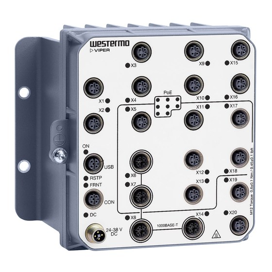
3.3. Hardware Overview RSTP FRNT 24-110 V 1000BA SE-T Description Description LED indicator 100 Mbps port Gbps port DC port Console port Protective earth connection USB port Figure 1. Location of interface ports and LED indicators Viper 12A Series... -
Page 11: Connector Pinout
-COM Table 3. Power connector Pin no. Signal Illustration No Connect. Do not connect. Table 4. Console connector Pin no. Signal Illustration VBUS No Connect. Do not connect. Table 5. USB connector Viper 12A Series... - Page 12 Signal Illustration MDI, MDI-X and auto MDI/MDI-X modes are supported. The table shows signals in MDI mode. Table 6. 100 Mbps Ethernet connector Pin no. Signal Illustration Table 7. Gbps connector Viper 12A Series...
-
Page 13: Led Indicators
X1 to X12 No link GREEN Link established GREEN Data traffic indication FLASH YELLOW Port alarm, or port is set in blocking state by link redundancy protocol Table 8. LED indicators 3.6. Dimensions Dimensions are stated in millimetres Viper 12A Series... - Page 14 164 ± 0,5 Grounding point screw M5x10 Figure 2. Dimensional drawing Viper 12A Series...
-
Page 15: Installation
NOTICE - UNUSED CONNECTORS Unused connectors must be covered by a protective cap (delivered with the unit), tightened to the specified torque in order to fulfill the specified ingress protection code. Viper 12A Series... -
Page 16: Cooling
4.5. EN 45545-2 Mounting Notes Two units can be mounted together and as a single interior non-listed group in the sense of EN 45545-2 definitions. For multiple units, the spacing requirements for interior non-listed groups must be met. Viper 12A Series... -
Page 17: Specifications
Reverse polarity protected Redundant power input Isolation to 2250 VDC to all other ports Connector 4-pin, male, M12, A-coded, recommended Westermo cables: 3146-1106 for 1.5 m 3146-1107 for 5 m Cable size M12, recommended cable area 0.5 mm² (minimum 0.25 mm²) - Page 18 Up to 150 m with CAT5e cable or better Isolation to 2250 VDC, 1 min Connector 4-pin, female, M12, D-coded, auto MDI/MDI-X, recommended Westermo cables: 3146-1100 M12-M12 - 1 m 3146-1101 M12-M12 - 5 m 3146-1103 RJ45-M12 - 1 m...
- Page 19 500 mA Circuit type SELV Isolation to Ethernet and DC ports: 2250 VDC No isolation to CON or chassis Connector 5-pin, female, M12, A-coded, recommended Westermo USB plug 3641-0190 Console port Electrical specification RS-232 Data rate 115.2 kbit/s Data format...
-
Page 20: Type Tests And Environmental Conditions
Fast Ethernet 2250 VDC, 1 min ports to all other ports Gbps Ethernet 2250 VDC, 1 min ports to all other ports 750 VDC after damp heat, according to EN 50155 Table 9. EMC and electrical conditions Viper 12A Series... - Page 21 Refer to "Safety and Regulations" chapter regarding touch temperature Operational at +85°C for a limited time Provided all connectors are connected with IP67 cabling or fitted with protective caps (delivered with the unit) and tightened to the specified torque. Table 10. Environmental and mechanical conditions Viper 12A Series...
-
Page 22: Revision Notes
2.1. Definition of personal injury at Caution level updated, 2.6.1 Mechanical data updated, 3.6 Dimensional drawing updated, 5.1 Transmission range for 100 Mbps ports and Gbps ports changed to 150 m, 5.2 Enclosure updated, Radiated + Conducted RF emission updated Viper 12A Series... - Page 23 Viper 12A Series...
- Page 24 Finland Singapore tiedot@westermo.fi sales@westermo.com.sg www.westermo.fi www.westermo.com.sg France Sweden infos@westermo.fr info.sverige@westermo.se www.westermo.fr www.westermo.se For complete contact information, please visit our website at www.westermo.com/contact or scan the QR code 6641-22511 REV. E 2017 09 Westermo Teleindustri AB, Sweden...
Need help?
Do you have a question about the Viper 12A Series and is the answer not in the manual?
Questions and answers