Sign In
Upload
Download
Table of Contents
Contents
Add to my manuals
Delete from my manuals
Share
URL of this page:
HTML Link:
Bookmark this page
Add
Manual will be automatically added to "My Manuals"
Print this page
×
Bookmark added
×
Added to my manuals
Manuals
Brands
Bosch Manuals
Computer Hardware
LTC 2380
User manual
Bosch LTC 2380 User Manual
Digital video quad processor
Hide thumbs
1
2
Table Of Contents
3
4
5
6
7
8
9
10
11
12
13
14
15
16
17
18
19
20
21
22
23
24
25
26
27
28
29
30
31
32
33
34
35
36
37
38
39
40
41
42
43
44
45
46
47
48
49
50
page
of
50
Go
/
50
Contents
Table of Contents
Bookmarks
Table of Contents
Table of Contents
1 Safety
Important Safety Instructions
Safety Precautions
Important Notices
Customer Support and Service
2 Unpacking
Parts List
Description
Installing the Video Quad
LTC 2380/90 Rear Panel Connections
LTC 2382/90 Rear Panel Connections
Wiring Requirements
Grounding Connection
Installing the Video Quad in a 19-Inch Rack
Programming the LTC 2382/90 Video Processor
LTC 2382/90 Front Panel Function Keys
Using the Function Keys (LTC 2382/90)
Operating the Video Quad Processors
Operating the LTC 2382/90 Video Quad Processor
Controlling the Video Quad Processor Remotely
Restoring Factory Default Settings
Maintenance
Technical Specifications
3 Index
Advertisement
Quick Links
1
Installing the Video Quad
2
Ltc 2380/90 Rear Panel Connections
3
Ltc 2382/90 Rear Panel Connections
4
Wiring Requirements
5
Programming the Ltc 2382/90 Video Processor
6
Ltc 2382/90 Front Panel Function Keys
7
Restoring Factory Default Settings
Download this manual
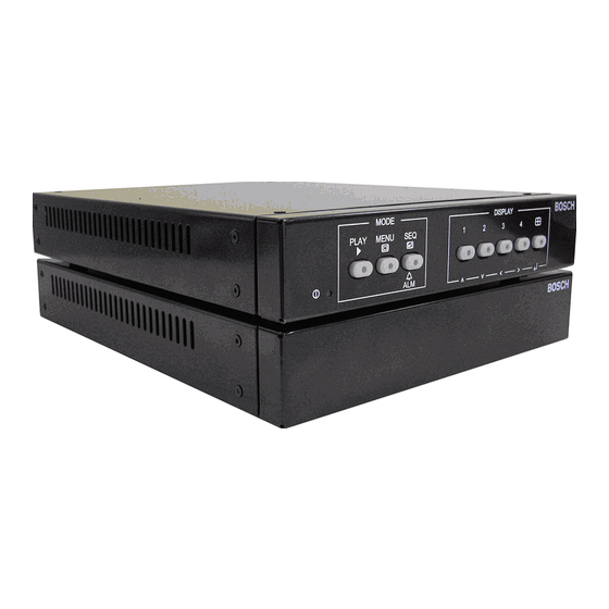
Digital Video Quad Processor
LTC 2380/90, LTC 2382/90
en
User Manuall
Table of
Contents
Previous
Page
Next
Page
1
2
3
4
5
Advertisement
Table of Contents
Need help?
Do you have a question about the LTC 2380 and is the answer not in the manual?
Ask a question
Questions and answers
Related Manuals for Bosch LTC 2380
Computer Hardware Bosch LTC 2382 User Manual
Digital video quad processor (50 pages)
Computer Hardware Bosch LTC 2382/90 User Manual
Digital video quad processor (50 pages)
Computer Hardware Bosch D5370-USB Installation Manual
Rps security block (8 pages)
Computer Hardware Bosch SMB365 Application Note
Multi sensor, wireless demo-board (46 pages)
Computer Hardware Bosch CL300 Manual
(167 pages)
Computer Hardware Bosch B820 Installation Manual
Sdi2 inovonics interface module (2 pages)
Computer Hardware Bosch Rexroth IndraDrive X Operating Instructions Manual
(140 pages)
Computer Hardware Bosch BMI090L User Manual
Desktop development 2.0 (24 pages)
Computer Hardware Bosch CM704B Installer's Reference Manual
8/16 zone expander module (9 pages)
Computer Hardware Bosch G10-1W Quick Install Manual
Wi-fi dongle (84 pages)
Computer Hardware Bosch MADI Card Plus Series User Manual
Multichannel audio digital interface card (50 pages)
Computer Hardware Bosch G10-3W Quick Install Manual
Wi-fi dongle (24 pages)
Computer Hardware Bosch AC-EXP Installation Instructions Manual
Expansion card for acc mt (44 pages)
Computer Hardware Bosch D8125MUX Operation And Installation Manual
Multiplex bus interface (24 pages)
Computer Hardware Bosch ADC 0064 A Installation Manual
(2 pages)
Computer Hardware Bosch FPE-1000-SLC Installation Manual
Signaling line circuit (20 pages)
This manual is also suitable for:
90
Ltc 2382
Ltc 2380/90
Ltc 2382/90
Table of Contents
Print
Rename the bookmark
Delete bookmark?
Delete from my manuals?
Login
Sign In
OR
Sign in with Facebook
Sign in with Google
Upload manual
Upload from disk
Upload from URL


Need help?
Do you have a question about the LTC 2380 and is the answer not in the manual?
Questions and answers