
Related Manuals for Cypress Suprex SPX-7200


Summary of Contents for Cypress Suprex SPX-7200
- Page 1 SPX-7200 Series Operations Manual Suprex® Reader Extender - Ethernet SPX-7200 EXP-2000 SPX-7200_MAN_082112...
- Page 2 This manual covers the operation and setup of the Cypress Suprex® SPX-7200 Ethernet series units. Overview The SPX-7200 series of Ethernet solutions provides an Ethernet bridge from Card Readers with gates or door hardware to most access control manufacturers panels. The SPX or Suprex® products include both the remote ( Door/Gate ) unit and the central ( AC Panel ) unit.
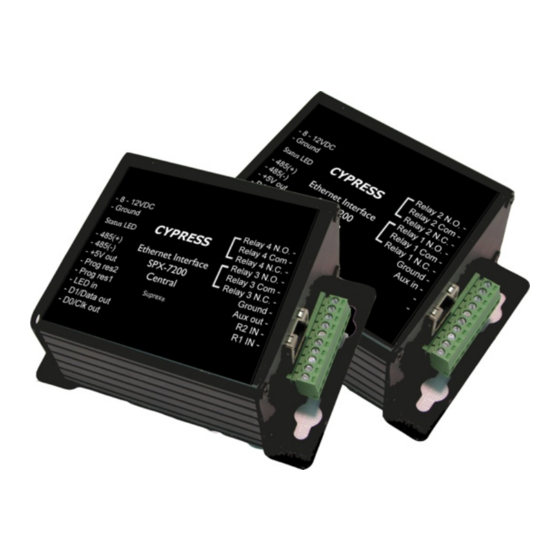
- Page 3 External connections and DIP Switch Settings 1 - 8 to 16 VDC In 2 - Ground 1- Relay 4 N.O. SPX-7200 2- Relay 4 Com Status LED Central 3 - Relay 4 N.C. 4 - Relay 3 N.O. 1 - exp (+)
- Page 4 Quick Reference For Typical Connections SPX-7200 Series Central Power +8 to +16 VDC Supply Ground Diagnostic LED R1 Input Controls Strike on Access Control Remote Panel LED In D1/Data Out R1 IN D0/Clock Out See page 14 for other strike control options...
- Page 5 Cypress Suprex® SPX-7200 Enclosure Dimensions 4.45 3.15 0.80 3.08 0.80 ø0.20 X 4 1.70 2.00...
- Page 6 Cypress Suprex® SPX-7200 Series - Indicators and Operating Modes LED Diagnostic Indicator: The LED Diagnostic indicator provides information on the operational status of the unit. If the units are not communicating, viewing the diagnostic indicator LED’s may help to determine the nature of the problem.
- Page 7 It may be necessary to change these settings to be compatible with the network that will be used in the final installation. The SPX-7200 system requires the use of fixed IP addresses to be assigned to the units. It may be necessary to coordinate with the System Administrator before placing the devices on a network.
- Page 8 Cypress Suprex® SPX-7200 Changing to UDP - Remote Port = 10001 Remote Host = 0.0.0.0 The Cypress SPX-7200 is factory set to use Use Broadcast = Checked TCPIP. To change to UDP use the Lantronix Device Address Table = All = 0 web interface with the following settings.
- Page 9 Setting IP Address - SPX-7200 1. Start the Lantronix XPort Installer software. The startup screen is shown above. Search Button 2. Click the “Search” button, after a brief delay, the connected device(s) should appear in the device list as shown above.
- Page 10 Setting IP Address - SPX-7200 Note: If the unit does not appear in the device list, check power and network connections. You will not be able to proceed if you are unable to see the unit to be configured in the device list.
- Page 11 Setting IP Address - SPX-7200 Once both units have had their IP addresses set, it will be necessary to tell the CENTRAL unit the address of the Remote unit. 5. After the IP addresses have been assigned to both units, select the CENTRAL unit in the device list.
- Page 12 Setting IP Address - SPX-7200 7. You should now have an open window like this. Press the ENTER key to enter setup mode. 8. A list of options will be presented, select Option #1 (Channel 1).
- Page 13 Setting IP Address - SPX-7200 9. All of the parameters will have been set as factory default, it will be necessary to set the address of the REMOTE unit in the Channel 1 parameters. In the example above, the parameters for the factory default settings have been entered.
- Page 14 Cypress Suprex® SPX-7200 Series - Door Strike and LED I/O Note: The LED and Door Strike operation of the Ethernet Suprex® differs from previous Suprex® versions. To activate the relay on the Remote unit, connect as shown below. These connections can be used to allow the Remote relay to operate a DOOR STRIKE, GATE, or other locking hardware.
- Page 15 Cypress Suprex® SPX-7200 Series - Door Strike and LED I/O The Cypress Suprex® SPX-7200 Series provides additional data channels to support access control hardware such as door strikes, tamper alarms, request to exit status, etc. These signals are sent to and from the Remote and Central units without the need to run additional wiring.
- Page 16 Cypress Suprex® SPX-7200 Series - Relay Controls Suprex® Central Suprex® Central Relay 2 IN Relay 1 IN Input Signal Input Signal Red arrow denotes direction of command signal Relay 2 N.O. Suprex® Remote Relay 2 Com Relay 2 N.C. Relay 1 N.O.
- Page 17 Cypress Suprex® SPX-7200 Series - Relay Controls Relay 4 N.O Suprex Central Relay 4 Com Relay 4 N.C. Relay 3 N.O. Contact Relay 3 Com Outputs Relay 3 N.C. Suprex Central Contact Outputs Red arrow denotes direction of command signal...
- Page 18 Using Supervised Contacts with the SPX-series Extenders Applies to the following products: SPX-5501, SPX-5601, SPX-5521, SPX-5621, SPX-7400, SPX-7410, SPX-7200, SPX-7500, All RIM series products. This application note describes the connections necessary to convey supervised contact status over a Suprex® communication link. The configurations described in this app note should apply to most panels that utilize supervised contacts.
- Page 19 Operation with Expansion Modules: The SPX-7200 system Remote and Central gateway units will operate as a standard pair Suprex® units, all of the I/O and data terminals are available for use with readers and access control systems. There are some minor differences in operation when using the expansion modules.
- Page 20 Cypress Suprex Ethernet Solution with Wiegand expansion modules Door / Parking Gate - Typical SPX-7200R (1) EXP-2000R EXP-2000R EXP-2000C EXP-2000C SPX-7200C (1) Card Reader Wiegand Data RS-485 Link - Multi-drop Control and I/O...
- Page 21 Cypress Suprex® Series - Wiegand Expansion Module Panel “Central” interface Power +8 to +16 VDC Supply Ground SPX-XXXX Central EXP(+) EXP(-) R1 Input Access Controls Control LED In Strike on Panel D1/Data Out R1 IN Remote D0/Clock Out 8 to 16 VDC In RLY4 N.O.
-
Page 22: Remote Unit
Cypress Suprex® Series - Wiegand Expansion Module Reader/Door “Remote” interface Power 8 to 16 VDC In SPX-XXXX Supply Ground Remote EXP (+) R1 N.O. EXP (-) Door R1 Com Strike R1 N.C. Output LED Out Card Reader D1/Data In D0/Clock In...
Need help?
Do you have a question about the Suprex SPX-7200 and is the answer not in the manual?
Questions and answers