
Related Manuals for Advantech AIMB-582


Summary of Contents for Advantech AIMB-582
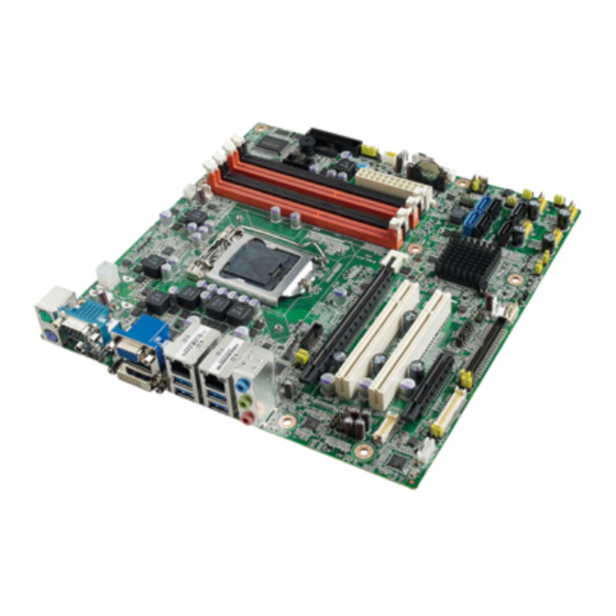
- Page 1 User Manual AIMB-582 Intel® Xeon® E3/Core™ i7/i5/i3 LGA1155 MicroATX with CRT/ DVI/eDP/LVDS/DP, 6 COM, Dual LAN, DDR3, PCIe x 16 and SATAIII...
- Page 2 The documentation and the software included with this product are copyrighted 2012 by Advantech Co., Ltd. All rights are reserved. Advantech Co., Ltd. reserves the right to make improvements in the products described in this manual at any time without notice.
- Page 3 Whether your new Advantech equipment is destined for the labo- ratory or the factory floor, you can be assured that your product will provide the reliability and ease of operation for which the name Advantech has come to be known.
-
Page 4: Declaration Of Conformity
LGA1155 PASS Processor 3.1 GHz Intel® Core® i3-2120 SR05Y Q0 32nm LGA1155 PASS Processor 3.3 GHz Intel® Celeron® Pro- cessor G540 SR05J 32nm LGA1155 PASS 2.50 GHz Intel® Pentium® Processor G850 SR05Q 32nm LGA1155 PASS 2.90 GHz AIMB-582 User Manual... -
Page 5: Ordering Information
1600 DDR3 Transcend DDR3 pass 1600 Ordering Information LVDS Part Number Chipset Memory USB 3.0 VGA DVI USB COM TPM /eDP Non- AIMB-582QG2-00A1E 1/(1) ECC/ AIMB-582WG2-00A1E C216 Non- 1/(1) *() means do not populated on MP version. AIMB-582 User Manual... - Page 6 It should be free of marks and scratches and in perfect working order upon receipt. As you unpack the AIMB-582, check it for signs of ship- ping damage. (For example, damaged box, scratches, dents, etc.) If it is damaged or it fails to meet the specifications, notify our service department or your local sales representative immediately.
-
Page 7: Table Of Contents
Board layout: Jumper and Connector Locations ........6 Figure 1.1 Jumper and Connector Location ........ 6 Figure 1.2 I/O Connectors ............6 AIMB-582 Board Diagram ................. 7 Figure 1.3 AIMB-582 Block Diagram ........... 7 Safety Precautions ..................8 Jumper Settings ..................8 1.8.1 How to Set Jumpers.............. - Page 8 Software API................70 4.2.2 Software Utility................72 Chapter Chipset Software Installation Utility Before You Begin..................74 Introduction ..................... 74 Windows XP/Windows 7 Driver Setup ............ 75 Chapter VGA Setup ......... 77 Introduction ..................... 78 Windows 7/XP..................78 AIMB-582 User Manual viii...
- Page 9 LVDS Power Jumper (JLVDS1/2) ............102 Table B.18:LVDS Power Jumper ..........102 B.19 LVDS Inverter (INV1) ................102 Table B.19:LVDS Inverter (INV1)..........102 B.20 ATX Power Connector (ATXPWR1, EATPWR1) ........103 Table B.20:ATX Power Connector (ATXPWR1, EATPWR1)..103 AIMB-582 User Manual...
- Page 10 Table B.23:JUSBPWR1-4 (USB Power Selection Connector) . 104 B.24 DMA Channel Assignments ..............105 Table B.24:DMA Channel Assignments ........105 B.25 Interrupt Assignments ................105 Table B.25:Interrupt Assignments ..........105 B.26 1st MB Memory Map................105 Table B.26:1st MB Memory Map ..........105 AIMB-582 User Manual...
-
Page 11: Chapter 1 General Information
Chapter General Information... -
Page 12: Introduction
Introduction AIMB-582 is designed with the Intel Q77/C216 for industrial applications that require both performance computing and enhanced power management capabilities. The motherboard supports Intel Core i7 3770 3.4GHz/ Core i5 3550S 3.0 GHz/ Core i3 3220 3.3 GHz Pentium G850 2.9 GHz/Celeron G540 2.5 GHz processor up to 8 MB L3 cache and DDR3 1333/1600 up to 32GB up to 16 GB. -
Page 13: Input/Output
USB port: Supports up to 8 USB 2.0 ports with transmission rates up to 480 Mbps and 4 USB 3.0 ports with transmission rates up to 5 Gbps. GPIO: AIMB-582 supports 8-bit GPIO from super I/O for general purpose con- trol application. 1.3.4 Graphics ... -
Page 14: Jumpers And Connectors
Board weight: 0.365 kg Jumpers and Connectors Connectors on the AIMB-582 motherboard link it to devices such as hard disk drives and a keyboard. In addition, the board has a number of jumpers used to configure your system for your application. - Page 15 ATX 20 Pin Main power connector (for System) DVI-D connector on rear panel COM2 Serial Port COM2, pin header 2x5 EDP1 eDP connector (2x10 pin header) JTAG Joint Test Action Group connector 2x5 P SMBUS1 SMBUS expansion pin header 1x4 P AIMB-582 User Manual...
-
Page 16: Board Layout: Jumper And Connector Locations
Board layout: Jumper and Connector Locations Figure 1.1 Jumper and Connector Location Figure 1.2 I/O Connectors AIMB-582 User Manual... -
Page 17: Aimb-582 Board Diagram
AIMB-582 Board Diagram Figure 1.3 AIMB-582 Block Diagram AIMB-582 User Manual... -
Page 18: Safety Precautions
1, 2, and 3. In this case you connect either pins 1 and 2, or 2 and 3. A pair of needle-nose pliers may be useful when set- ting jumpers. AIMB-582 User Manual... -
Page 19: Cmos Clear (Cmos1)
1.8.2 CMOS Clear (CMOS1) The AIMB-582 motherboard contains a jumper that can erase CMOS data and reset the system BIOS information. Normally this jumper should be set with pins 1-2 closed. If you want to reset the CMOS data, set CMOS1 to 2-3 closed for just a few seconds, and then move the jumper back to 1-2 closed. -
Page 20: Jusbpwr1-4 (Usb Power Selection Connector)
ATX Mode Default ATX Mode AT Mode 2-3 closed 1-2 closed 1.8.6 JIR1+JOB1+JWD1: Watchdog Timer Output and OBS Alarm Option Table 1.7: JIR1+JOB1+JWD1: Watchdog Timer Output and OBS Alarm Option Pin Name SIO_WG# SIO_IRRX SRST# ERR_BEEP SIO_IRTX OBS_BEEP AIMB-582 User Manual... -
Page 21: Jme1:Bios Update Me Mode Selector
BIOS been updated. 1.8.8 JCASE1: Case Open Sensor The AIMB-582 motherboard contains a jumper that provides a chassis open sensor. The buzzer on the motherboard beeps when the case is opened. System Memory AIMB-582 has four 240-pin memory sockets for 1333/1600 MHz memory modules with maximum capacity of 32 GB (Maximum 8 GB for each DIMM). -
Page 22: Memory Installation Procedures
1.11 Cache Memory The AIMB-582 supports a CPU with one of the following built-in full speed L3 caches: 8MB for Intel Xeon E3 1275v2 8MB for Intel Xeon E3 1275... -
Page 23: Chapter 2 Connecting Peripherals
Chapter Connecting Peripherals... -
Page 24: Introduction
USB Ports (LAN1_USB01/LAN2_USB23/USB45/ USB89/USB1011/USB1213) The AIMB-582 provides up to 12 USB ports. The USB interface complies with USB Specification Rev 2.0 supporting transmission rates up to 480 Mbps and Rev 3.0 sup- porting transmission rate up to 5 Gbps and is fuse protected. The USB interface can be disabled in the system BIOS setup. -
Page 25: Usb Power Switch
USB Power Switch AIMB-582 allows users to set USB power between +5 VSB and +5 V. When the jumper is set as +5 V (default 2-3 pin), the board doesn't support wake from S3 via keyboard or mouse. If need to set as +5 Vsb, need to modify the jumper (1-2 pin) and ask for to modify the customized BIOS at the same time. -
Page 26: Vga/Dvi-D Connector (Vga1+Dvi 1) Connector
VGA/DVI-D Connector (VGA1+DVI 1) Connector AIMB-582 includes VGA and DVI interfaces that can drive conventional VGA and DVI displays. VGA is a standard 15-pin D-SUB connector commonly used for VGA. Pin assignments for VGA and DVI connectors are detailed in Appendix B. -
Page 27: Serial Ports (Com1~Com6)
Serial Ports (COM1~COM6) COM1/COM2 AIMB-582 supports six serial ports. COM1, COM2, COM4-6 supports RS-232. COM3 supports RS-232/422/485 (with 5V/12V power). JSETCOM3 is used to select the RS- 232/422/485 mode for COM3. These ports can connect to serial devices, such as a mouse or a printer, or to a com- munications network. -
Page 28: Display Port (Dp1)
Display Port (DP1) AIMB-582 has one external DP connector to supports the Display Port panel. AIMB-582 User Manual... -
Page 29: Ps/2 Keyboard And Mouse Connector (Kbms1)/External Ps/2 Keyboard
(KBMS2) Two 6-pin mini-DIN connectors (KBMS1) on the motherboard provide connection to a PS/2 keyboard and a PS/2 mouse, respectively. KBMS2 is for supporting the 2nd PS/ 2 keyboard and PS/2 mouse by a cable P/N 1700018699. AIMB-582 User Manual... -
Page 30: Cpu Fan Connector (Cpu_Fan1)
If a fan is used, this connector supports cooling fans of 500 mA (6 W) or less. System FAN Connector (SYSFAN1/2/3/4) If a fan is used, this connector supports cooling fans of 500 mA (6 W) or less. AIMB-582 User Manual... -
Page 31: Front Panel Connectors (Jfp1/Jfp2/Jfp3)
External speaker (JFP1/SPEAKER) JFP1/SPEAKER is a 4-pin connector for an external speaker. If there is no external speaker, the AIMB-582 provides an onboard buzzer as an alternative. To enable the buzzer, set pins 7 & 10 as closed. AIMB-582 User Manual... -
Page 32: Power Led And Keyboard Lock Connector
2-3 closed pins 1-2 closed panel switch via cable jumper setting System On System Suspend Fast flashes Fast flashes Fast flashes System Off Slow flashes 2.11 Line Out, Mic In Connector (AUDIO1) Line Out Mic In AIMB-582 User Manual... -
Page 33: Digital Audio Connector (Spdif_Out1)
This connector is for the S/PDIF audio module to allow digital output sound. Connect one end of the S/PDIF audio cable to this connector and the other end to the S/PDIF module. Note! The S/PDIF module is purchased separately. AIMB-582 User Manual... -
Page 34: Serial Ata Interface (Sata1 ~ Sata6)
2.13 Serial ATA Interface (SATA1 ~ SATA6) AIMB-582 features a high performance Serial ATA interface (up to 300 MB/s) and Serial ATA III interface (up to 600 MB/s) which eases hard drive cabling with thin, space-saving cables. Note! AIMB-582 on board SATA only supports Fedora 14 and 15 and SATA mode in BIOS should be set as AHCI mode. -
Page 35: 8-Pin Alarm Board Connector (Volt1)
2.15 PCI express x16 slot AIMB-582 provides a PCIe x16 slot for users to install add-on cards when their appli- cations require higher graphic performance than the CPU embedded graphics con- troller can provide. -
Page 36: Front Panel Audio Connector (Fpaud1)
I/O module cable. Note! For motherboards with the optional HD Audio feature, we recommend that you connect a high-definition front panel audio module to this con- nector to take advantage of the motherboard’s high definition audio capability. AIMB-582 User Manual... -
Page 37: Atx Power Connector (Eatxpwr1, Atx12V1)
Please connect the ATX12V1 connector with the PSU ATX 12V 4- pin connector. For a fully configured system, we recommend that you use a power supply unit (PSU) that complies with ATX 12 V Specification 2.0 (or later version) and provides a minimum power of 180 W. AIMB-582 User Manual... -
Page 38: Spi Flash Connector(Spi_Cn1)
2.18 SPI Flash connector(SPI_CN1) The SPI flash card pin header may be used to flash the BIOS if the AIMB-582 cannot power on. AIMB-582 User Manual... -
Page 39: Lvds Inverter Connector (Inv1)
2.19 LVDS Inverter Connector (INV1) Note! Signal Description Signal Signal Description Vadj=0.75 V (Recommended: 4.7 KΩ, >1/16 W) ENBKL LCD backlight ON/OFF control signal AIMB-582 User Manual... -
Page 40: Lvds Connector (Lvds1)
2.20 LVDS Connector (LVDS1) 2.21 General purpose I/O Connector (GPIO1) AIMB-582 User Manual... -
Page 41: Edp Connector (Edp1)
2.22 eDP Connector (eDP1) 2.23 JTAG Connector (JTAG1) AIMB-582 User Manual... - Page 42 AIMB-582 User Manual...
-
Page 43: Bios Operation
Chapter BIOS Operation... -
Page 44: Introduction
BIOS Setup The AIMB-582 Series system has AMI BIOS built in, with a SETUP utility that allows users to configure required settings or to activate certain system features. The SETUP saves the configuration in the FLASH of the motherboard. When the power is turned off, the battery on the board supplies the necessary power to pre- serve the FLASH. -
Page 45: Main Menu
System Date using the <Arrow> keys. Enter new values through the keyboard. Press the <Tab> key or the <Arrow> keys to move between fields. The date must be entered in MM/DD/YY format. The time must be entered in HH:MM:SS format. AIMB-582 User Manual... -
Page 46: Advanced Bios Features
3.2.2 Advanced BIOS Features Select the Advanced tab from the AIMB-582 setup screen to enter the Advanced BIOS Setup screen. You can select any of the items in the left frame of the screen, such as CPU Configuration, to go to the sub menu for that item. You can display an Advanced BIOS Setup option by highlighting it using the <Arrow>... - Page 47 3.2.2.1 PCI Subsystem Settings Above 4G Decoding [Disabled] Enables or disables 64bit capable devices to be decoded on above 4G address space. Note! Only if system support 64 bit PCI decoding. AIMB-582 User Manual...
- Page 48 PowerOn by Modem [ Disabled ] Allows the system to be awakened from an ACPI sleep state by a wake-up sig- nal from a modem that supports wake-up function. Power Type [ ATX ] AIMB-582 User Manual...
- Page 49 Note! The following items function only when a TPM module is installed on board. Security Device Support [ Disable ] AIMB-582 User Manual...
- Page 50 3.2.2.4 S5RTC Wake Settings The item allow you enable or disable system wake up on alarm event. Wake system with Fixed Time [ Disabled ] Wake system with dynamic Time [ Disabled ] AIMB-582 User Manual...
- Page 51 This reduces the latency associ- ated with memory reads. Adjacent Cache Line Prefetch [ Enabled ] This item allows users to enable or disable the adjacent cache line prefetch fea- ture. AIMB-582 User Manual...
- Page 52 SATA Controllers [ Enabled ] Enable or disable SATA Function. Note! This item appears only when you set SATA mode to "IDE Mode". SATA Mode [ IDE ] This can be configured as IDE or AHCI mode. AIMB-582 User Manual...
- Page 53 This item can be configured only when the Intel SMX, Intel Virtualization Tech- nology (VT) and Intel Virtualization for Directed IO (VT-d) technologies are all enabled. This item allow you to enable or disable Intel Trusted Execution Tech- nology. AIMB-582 User Manual...
- Page 54 Watchdog [ Disabled ] When set to [Enabled], the Watchdog timer will monitor the time taken for each task performed by a software or hardware. – OS Timer [ 0 ] – BIOS Timer [ 0] AIMB-582 User Manual...
- Page 55 This is just a workaround item under OS without EHCI hand-off support. Device Reset time out USB mass storage device reset time out. Mass Storage Devices [ Auto ] Shows USB mass storage device information. AIMB-582 User Manual...
- Page 56 3.2.2.10 SMART Settings SMART Self Test [Disabled] 3.2.2.11 Super IO Configuration AIMB-582 User Manual...
- Page 57 Serial Port 1 Configuration – Serial Port [ Enabled ] – Change Settings [ Auto ] To select an optimal setting for serial port 1. Serial Port 2 Configuration AIMB-582 User Manual...
- Page 58 Parallel Port Configuration – Parallel Port [ Enabled ] To enable or disable Parallel Port. – Change Settings [ Auto ] To select an optimal setting for parallel port. – Device Mode [ ECP and EPP 1.9 Mode ] AIMB-582 User Manual...
- Page 59 OS to protect the system from overheating damage. CPUFAN Mode Setting [ Disabled ] “Enable or Disable” CPUFAN Mode to SMART FAN setting. SYSFAN Mode Setting [ Disabled ] “Enable or Disable” SYSFAN Mode to SMART FAN setting. AIMB-582 User Manual...
- Page 60 AIMB-582QG2 version supports 2nd super IO for COM 3-6, so this page of the BIOS menu is to set respective serial port configuration. Serial Port 3 Configuration – Serial Port [ Enabled ] To “enable or disable” Serial Port 3. AIMB-582 User Manual...
- Page 61 When the COM is to set as RS-485, it supports auto flow control function. Serial Port 4 Configuration – Serial Port [Enabled] To "enable or disable" serial port 4. – Change Settings [ Auto ] To select an optimal setting for serial port 4. AIMB-582 User Manual...
- Page 62 Serial Port 5 Configuration – Serial Port [Enabled] To “enable or disable” serial port 5. – Change Settings [ Auto ] To select an optimal setting for serial port 5. AIMB-582 User Manual...
- Page 63 To “enable or disable” serial port 6. – Change Setting [ Auto ] To select an optimal setting for serial port 6. 3.2.2.14 Serial Port Console Redirection Console Redirection [ Enabled ] Enable or disable the console redirection feature AIMB-582 User Manual...
- Page 64 3.2.2.15 CPU PPM Configuration EIST [ Enabled ] This item can enable / disable Intel CPU speedstep. AIMB-582 User Manual...
-
Page 65: Chipset Configuration Setting
Users can display a Chipset Setup option by highlighting it using the <Arrow> keys. All Chipset Setup options are described in this section. The Chipset Setup screens are shown below. The sub menus are described on the following pages. 3.3.1 PCH-IO Configuration AIMB-582 User Manual... - Page 66 3.3.1.1 PCI Express Configuration AIMB-582 User Manual...
- Page 67 PCI Express Root Port 1 [ Enabled ] ASPM Support [ Auto ] PCIe Speed [ Auto ] 3.3.1.2 USB Configuration AIMB-582 User Manual...
- Page 68 XHCI Pre-Boot Driver [Enabled] Enable or disable XHCI Pre-Boot Driver support. 3.3.1.3 PCH Azalia Configuration AIMB-582 User Manual...
- Page 69 Azalia [ Auto] This item set for control Detection of the Azalia device. [Disabled] = Azalia will be unconditionally disabled. [Enabled] = Azalia will be unconditionally enabled [Auto] = Azalia will be enabled if present, disabled otherwise. AIMB-582 User Manual...
-
Page 70: System Agent (Sa) Configuration
3.3.2 System Agent (SA) Configuration 3.3.2.1 C-State Pre Wake C-State Pre-Wake [ Enabled] Disable or enable C-State Pre-Wake feature for ARAT. AIMB-582 User Manual... - Page 71 3.3.2.2 Graphics Configuration Primary Display [ Auto ] Select the video device which will be activated during POST. LCD control AIMB-582 User Manual...
- Page 72 PASS PASS PASS DVI+LVDS PASS PASS PASS DVI+DP PASS PASS PASS LVDS+DP PASS PASS PASS LVDS+DVI=>HDMI PASS PASS PASS DP+DVI=>HDMI PASS PASS PASS CRT+DVI+DP PASS CRT+DVI+LVDS PASS CRT+DP+LVDS PASS CRT+DP+DVI=>HDMI PASS CRT+LVDS+DVI=>HDMI PASS LVDS+DP+DVI PASS LVDS+DP+DVI=>HDMI PASS AIMB-582 User Manual...
- Page 73 Active LVDS Active LVDS [ Disable] Note! When you enable LVDS type, customers can choose different resolution settings from the table. Default resolution setting is "800 x 600 18-bit" (see below) AIMB-582 User Manual...
- Page 74 3.3.2.3 NB PCIe Configuration AIMB-582 User Manual...
-
Page 75: Boot Setting
Boot Setting Setup Prompt Timeout User the <+> and <-> keys to adjust the number of seconds to wait for setup activation key. Bootup NumLock State [ On ] AIMB-582 User Manual... -
Page 76: Security Setting
Select this option and press <ENTER> to access the sub menu, and then type in the password. Set the Administrator password. User Password Select this option and press <ENTER> to access the sub menu, and then type in the password. Set the User Password. AIMB-582 User Manual... -
Page 77: Save & Exit Configuration
Select Restore Defaults from the Exit menu and press <Enter>. Save as User Default Save the all current settings as a user default. Restore User Default Restore all settings to user default values. Boot Override Shows the boot device types on the system. AIMB-582 User Manual... - Page 78 AIMB-582 User Manual...
-
Page 79: Software Introduction & Service
Chapter Software Introduction & Service... -
Page 80: Introduction
Introduction The mission of Advantech Embedded Software Services is to "Enhance quality of life with Advantech platforms and Microsoft® Windows® embedded technology." We enable Windows® Embedded software products on Advantech platforms to more effectively support the embedded computing community. Customers are freed from the hassle of dealing with multiple vendors (hardware suppliers, system integrators, embedded OS distributors) for projects. - Page 81 System Throttling Refers to a series of methods for reducing power consump- tion in computers by lowering the clock frequency. This API allows the user to adjust the clock from 87.5% to 12.5%. AIMB-582 User Manual...
-
Page 82: Software Utility
Telnet server and FTP server so the administrator can attempt to rescue the system. Note: This function requires BIOS customization. AIMB-582 User Manual... -
Page 83: Chipset Software Installation Utility
Chapter Chipset Software Installation Utility... -
Page 84: Before You Begin
To facilitate the installation of the enhanced display drivers and utility software, read the instructions in this chapter carefully. The drivers for AIMB-582 are located on the software installation CD. The driver in the folder of the driver CD will guide and link you to the utilities and drivers under a Windows system. -
Page 85: Windows Xp/Windows 7 Driver Setup
Windows XP/Windows 7 Driver Setup Insert the driver CD into your system's CD-ROM drive. Navigate to the "01. Chip" folder and click "infinst.autol.exe" to complete driver installation. AIMB-582 User Manual... - Page 86 AIMB-582 User Manual...
-
Page 87: Vga Setup
Chapter VGA Setup... -
Page 88: Introduction
See Chapter 5 for information on installing the CSI utility. Insert the driver CD into your system's CD-ROM drive. Navigate to the "VGA" folder and click "setup.exe" to complete the installation of the drivers for Windows 7 and Windows XP. AIMB-582 User Manual... - Page 89 AIMB-582 User Manual...
- Page 90 AIMB-582 User Manual...
-
Page 91: Lan Configuration
Chapter LAN Configuration... -
Page 92: Introduction
Introduction The AIMB-582 has dual Gigabit Ethernet LANs via dedicated PCI Express x1 lanes (Intel 82579LM (LAN1) and 82583V (LAN2)) that offer bandwidth of up to 500 MB/ sec, eliminating the bottleneck of network data flow and incorporating Gigabit Ether- net at 1000 Mbps. -
Page 93: Windows® 7/Xp Driver Setup (Intel 82579Lm/82583V)
Windows® 7/XP Driver Setup (Intel 82579LM/ 82583V) Insert the driver CD into your system's CD-ROM drive. Select the LAN folder then navigate to the directory for your OS. AIMB-582 User Manual... - Page 94 AIMB-582 User Manual...
- Page 95 Appendix Programming the Watchdog Timer...
-
Page 96: Appendix A Programming The Watchdog Timer
Programming the Watchdog Timer AIMB-582's watchdog timer can be used to monitor system software operation and take corrective action if the software fails to function within the programmed period. This section describes the operation of the watchdog timer and how to program it. - Page 97 Unlock NCT6776F Select register of watchdog timer Enable the function of the watchdog timer Use the function of the watchdog timer Lock NCT6776F AIMB-582 User Manual...
-
Page 98: Table A.1: Watchdog Timer Registers
Bit 5: Write 1 to generate a timeout signal immedi- ately and automatically return to 0. [default=0] Bit 4: Read status of watchdog timer, 1 means timer is “timeout”. Write this address to I/O port 2E (hex) to lock the AA (hex) ----- watchdog timer 2. AIMB-582 User Manual... -
Page 99: Example Program
Inc dx Mov al,10 Out dx,al ;----------------------------------------------------------- Dec dx ; Lock NCT6776F Mov al,0aah Out dx,al Enable watchdog timer and set 5 minutes as timeout interval ;----------------------------------------------------------- Mov dx,2eh ; Unlock NCT6776F Mov al,87h Out dx,al Out dx,al AIMB-582 User Manual... - Page 100 Enable watchdog timer to be reset by mouse ;----------------------------------------------------------- Mov dx,2eh ; Unlock NCT6776F Mov al,87h Out dx,al Out dx,al ;----------------------------------------------------------- Mov al,07h ; Select registers of watchdog timer Out dx,al Inc dx Mov al,08h Out dx,al ;----------------------------------------------------------- AIMB-582 User Manual...
- Page 101 Dec dx ; Enable the function of watchdog timer Mov al,30h Out dx,al Inc dx Mov al,01h Out dx,al ;----------------------------------------------------------- Dec dx ; Enable watchdog timer to be strobed reset by keyboard Mov al,0f7h Out dx,al Inc dx In al,dx Or al,40h Out dx,al AIMB-582 User Manual...
- Page 102 Dec dx ; Generate a time-out signal Mov al,0f7h Out dx,al ;Write 1 to bit 5 of F7 register Inc dx In al,dx Or al,20h Out dx,al ;----------------------------------------------------------- Dec dx ; Lock NCT6776F Mov al,0aah Out dx,al AIMB-582 User Manual...
-
Page 103: Appendix B Pin Assignments
Appendix Pin Assignments... -
Page 104: Usb Header (Usb45,Usb89,Usb1011,Usb1213)
USB Header (USB45,USB89,USB1011,USB1213) Table B.1: USB Header (USB56) Signal Signal +V5_USB +V5_USB USB4N USB5N USB4P USB5P VGA Connector (VGA1) Table B.2: VGA Connector (VGA1) Signal Signal CRT_VCCIN VGA_G VGA_B V_SDAT H-SYNC V-SYNC V_SCLK AIMB-582 User Manual... -
Page 105: Edp1: Edp Connector
EDP0- EDP3- EDP0+ EDP3+ EDP1- EDP1+ EAUX- EAUX+ EDP2- EDP2+ DDPD_DP_HPD VDD_1 VDD_LVDS1 SPI_CN1: SPI Fresh Card Pin Connector Table B.4: SPI_CN1: SPI Fresh Card Pin Connector Pin Name Pin Name +3.3 V_SPI SPI_CS# SPI_CLK SPI_SO_R1 SPI_SI AIMB-582 User Manual... -
Page 106: Ps/2 Keyboard And Mouse Connector (Kbms1)
PS/2 Keyboard and Mouse Connector (KBMS1) Table B.5: PS/2 Keyboard and Mouse Connector (KBMS1) Signal KB DATA KB VCC KB CLK M_DATA M_VCC M_CLK RS-232 Interface (COM3/4/5/6) AIMB-582 User Manual... -
Page 107: Table B.6: Rs-232 Interface (Com3/4/5/6)
COM4_RTS# COM4_SOUT COM4_CTS# COM4_DTR# COM4_RI# COM5_DCD# COM5_DSR# COM5_SIN COM5_RTS# COM5_SOUT COM5_CTS# COM5_DTR# COM5_RI# COM6_DCD# COM6_DSR# COM6_SIN COM6_RTS# COM6_SOUT COM6_CTS# COM6_DTR# COM6_RI# CPU Fan Power Connector (CPU_FAN1) Table B.7: CPU Fan Power Connector (CPU_FAN1) Pin Name CPU_FAN_PWN CPU_FAN_SPEED AIMB-582 User Manual... -
Page 108: System Fan Power Connector (Sys_Fan1/2/3/4)
You can use an LED to indicate when the single board computer is on. Pin 1 of JFP3 supplies the LED's power, and Pin 3 is the ground. Table B.9: Power LED & Keyboard Lock Connector (JFP3) Pin Name +3 V SUSLED KEYLOCK# AIMB-582 User Manual... -
Page 109: Power Switch/Hdd Led/Smbus/Speaker (Jfp1/2)
Pin Name SPK_CN17P1 + V3.3 PANSWIN# SPK_CN17P2 SATALED# SPK_CN17P3 SNMP_SDA SYS_RST# SPK_CN17P4 SNMP_SCL B.11 USB/LAN ports (LAN1_USB12/LAN2_USB34) Table B.11: USB Port Signal Signal Data0+ Data0- Table B.12: Ethernet 10/100 Mbps RJ-45 Port Signal Signal XMT+ XMT- RCV- RCV+ AIMB-582 User Manual... -
Page 110: Line Out, Mic In Connector (Audio1)
Table B.14: AT/ATX Mode (PSON1) Pin Name +V3.3 B.15 HD Audio Interface (FPAUD1) Table B.15: HD Audio Interface (FPAUD1) Description Audio front panel connector Pin Name Pin Name MIC2_L MIC2_R PRESENCE# LINE2-R MIC2-JD FRONT-IO-SENSE_R 8 LINE2-L LINE2-JD AIMB-582 User Manual... -
Page 111: Gpio Pin Header (Gpio1)
GPIO1 GPIO5 GPIO2 GPIO6 GPIO3 GPIO7 B.17 LVDS Connector: LVDS1 Table B.17: LVDS Connector: LVDS1 Pin Name Pin Name Pin Name VDD_LVDS1 LA_DATAP1 VDD_LVDS1 LB_DATAP1 L_DDC_CLKR L_DDC_DATR VDD_LVDS1 LA_DATAN2 VDD_LVDS1 LB_DATAN2 LA_DATAN0 LA_DATAP2 LA_DATAN3 LB_DATAN0 LB_DATAP2 LB_DATAN3 AIMB-582 User Manual... -
Page 112: Lvds Power Jumper (Jlvds1/2)
B.18 LVDS Power Jumper (JLVDS1/2) * default setting Table B.18: LVDS Power Jumper LVDS1 LVDS2 Signal Signal +V3.3 +V12 +V_LCD_S (LCD power) B.19 LVDS Inverter (INV1) Table B.19: LVDS Inverter (INV1) Pin Name +V12_INV1 LVDS1_ENBKL LVDS1_VBR +V5_INV1 AIMB-582 User Manual... -
Page 113: Atx Power Connector (Atxpwr1, Eatpwr1)
B.20 ATX Power Connector (ATXPWR1, EATPWR1) Table B.20: ATX Power Connector (ATXPWR1, EATPWR1) Pin Name Pin Name +3.3V +3.3V +3.3V -12V PS_ON# ATXPG 5VSB +12V +12V +3.3V AIMB-582 User Manual... -
Page 114: Atx 12 V Connector (Atx12V1)
+V12_4P B.22 JTAG ( Joint Test Action Group Connector) Table B.22: Joint Test Action Group (JTAG) Pin Name BSCAN_ON# TRST# B.23 JUSBPWR1-4 (USB Power Selection Connector) Table B.23: JUSBPWR1-4 (USB Power Selection Connector) Pin Name +V5_DUAL +V5_USB AIMB-582 User Manual... -
Page 115: Dma Channel Assignments
1st MB Memory Map Table B.26: 1st MB Memory Map Addr. range (Hex) Device E0000h - FFFFFh BIOS CC000h - DFFFFh Unused C0000h - CBFFFh VGA BIOS A0000h - BFFFFh Video Memory 00000h - 9FFFFh Base memory AIMB-582 User Manual... - Page 116 No part of this publication may be reproduced in any form or by any means, electronic, photocopying, recording or otherwise, without prior written permis- sion of the publisher. All brand and product names are trademarks or registered trademarks of their respective companies. © Advantech Co., Ltd. 2012...
Need help?
Do you have a question about the AIMB-582 and is the answer not in the manual?
Questions and answers