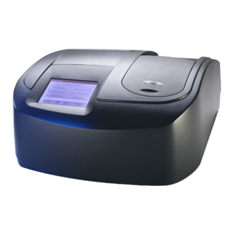
Hach DR 5000 User Manual
Spectrophotometer
Hide thumbs
Also See for DR 5000:
- Instruction sheet (10 pages) ,
- Instruction manual (8 pages) ,
- Instruction sheet (4 pages)

Related Manuals for Hach DR 5000


Summary of Contents for Hach DR 5000
- Page 1 DOC022.53.00654 DR 5000 USER MANUAL January 2008, Edition 2 © HACH Company, 2007–2008. All rights reserved. Printed in Germany.
-
Page 3: Table Of Contents
5.2.6 PC and printer ... 29 5.2.6.1 Printer setup ... 29 5.2.6.2 Print data ... 31 5.2.6.3 HACH Data Trans ... 31 5.2.7 Password ... 32 5.2.7.1 Password deactivation ... 33 5.3 Store, recall, send and delete data ... 35 5.3.1 The Data Log ... - Page 4 Table of Contents 5.4 Stored Programs ... 42 5.4.1 Select a saved test/method; enter user-specific basic data ... 42 5.4.2 Stored program options ... 42 5.4.3 Use of program timers ... 44 5.4.4 Set the reading mode ... 44 5.4.4.1 Take single wavelength measurements (single reading) ... 45 5.4.4.2 Take single wavelength measurements (continuous readings) ...
- Page 5 6.4 Single Wavelength (absorbance, concentration and transmittance measurements) ... 87 6.4.1 Set up single wavelength mode ... 87 6.4.2 Take single wavelength measurements (single reading) ... 89 6.4.3 Take single wavelength measurements (continuous readings) ... 89 6.5 Multi-Wavelength mode – measurements at more than one wavelength ... 90 6.5.1 Set the reading mode at different wavelengths ...
- Page 6 Table of Contents...
-
Page 7: Section 1 Specifications
Section 1 Specifications Performance specifications Operating mode Source lamp Wavelength range Wavelength accuracy Wavelength reproducibility Wavelength resolution Wavelength calibration Wavelength selection Scanning speed Spectral bandwidth Photometric range Photometric accuracy Photometric linearity Stray light Data storage User programs Physical and environmental specifications Width Height Depth... - Page 8 Specifications...
-
Page 9: Section 2 General Information
Section 2 General Information 2.1 Safety information 2.1.1 Use of hazard information 2.1.2 Precautionary labels This symbol, if noted on the instrument, references the instruction manual for operation and/or safety information. This symbol, if noted on the instrument, indicates a hot surface. Electrical equipment marked with this symbol may not be disposed of in European public disposal systems after 12 August of 2005. -
Page 10: Class 1 Laser
General Information 2.1.3 Class 1 LASER 2.1.4 Chemical and Biological Safety 2.1.5 Source Lamp Safety A Class 1 LASER is installed in this instrument. Class 1 LASERS are products where the radiant power of the LASER beam accessible (the accessible emission) is always below the Maximum Permissible Exposure value. -
Page 11: Overview Of Product
Single Wavelength Mode, Multi-Wavelength Mode, Wavelength Scanning Mode and Time Course Mode. The DR 5000 is used for testing in visible and ultraviolet wavelengths. A gas-filled tungsten lamp produces light in the visible spectrum (320 to 1100 nm), and a deuterium lamp available produces light in the ultraviolet spectrum (190 to 360 nm). - Page 12 General Information...
-
Page 13: Section 3 Installation
WARNING Electrical and Fire Hazards. Use only the provided power supply. Only qualified personnel should conduct the tasks described in this section of the manual. The DR 5000 Spectrophotometer comes packaged with the following items: • DR 5000 Spectrophotometer •... -
Page 14: Connection
USB type A USB type B On/Off switch The DR 5000 has three USB interfaces as a standard feature, located on the back of the instrument The USB Type A interfaces are used for communications with a printer, USB memory stick or keyboard. A USB memory stick is used to update instrument software. -
Page 15: Cell Compartment, Multi Cell Holder, 100 Mm Cell Adapter (Optional)
Cell compartment Figure 2 Cell compartment Cell compartment for 13 mm or 16 mm round cuvettes/vials only The DR 5000 Spectrophotometer comes equipped with a Multi Cell Holder (Figure 3 on page 16) which is the Standard Holder, provided with each instrument. The Multi Cell Holder can accommodate the following cell types: •... -
Page 16: Mm Adapter (Optional)
Installation square 10 mm cell 20 mm rectangular cell 50 mm rectangular cell 3.4.1 100 mm adapter (optional) 100 mm rectangular cell Figure 3 Multi Cell Holder (Top and Bottom) 1“ round cell square 1“ Figure 4 100 mm Cell Adapter cell... -
Page 17: Installation Multi Cell Holder
3.4.2 Installation Multi Cell Holder Assembly of the Multi Cell Holder: 1. Open the cell compartment. 2. Identify the correct opening for the selected cell type in the Multi Cell Holder. 3. Insert the Multi Cell Holder in the cell compartment in such a way that the name of the selected cell type can be read directly and the cell opening is at the front. -
Page 18: Beam Path
Tungsten lamp Mirror Grating Reference element Mirror Splitter mirror Filter Figure 6 shows the beam path of the DR 5000: Figure 6 Beam path 10 Exit slit 11 Cell compartment 12 Lens 13 Round cuvette/vial compartment 14 Measurement element 15 Monochromator... -
Page 19: Section 4 Start Up
Section 4 Start Up 4.1 Power the instrument on and off 4.2 Language selection 4.3 Self-Check 1. Plug in power supply. 2. Close the empty cell compartment. 3. Turn the instrument on by pressing the power switch on the back. Note: Do not turn the instrument off and on in rapid succession. - Page 20 Start Up...
-
Page 21: Section 5 Standard Operations
A space can be entered by using the underscore on the YZ_ key. Note: A USB keyboard (with US keyboard layout) or a USB Barcode handset scanner can be used for input (see Table 1 Alphanumeric keypad Function When entering alphabetic characters (ex. user-entered units), this key allows to toggle between upper and lower case letters. -
Page 22: Main Menu
LANGE Programs) The DR 5000 Procedures Manual contains illustrated, step-by-step procedures for analyses using HACH programs. The working procedures for LANGE tests are included in the test packs. User programs make "made to measure analysis" possible: –Users can program methods they have developed themselves User Programs –Existing HACH and LANGE methods can be stored as user programs. -
Page 23: Instrument Setup Mode
5.2 Instrument Setup mode 5.2.1 Operator ID 1. Select Instrument Setup in the Main Menu. A selection of functions appears in order to configure the functions of the instrument. This display appears when the multi-cell holder is installed or the 13 mm round cuvette/vial compartment is used. -
Page 24: Sample Id
2. Press New to enter a new Sample ID. 3. Use the alphanumeric keypad to enter a new Sample ID. Note: If a USB Barcode handset scanner ( see is connected, Sample IDs can also be scanned. 4. Press OK to confirm. -
Page 25: Date And Time
Sample ID is already assigned, select the Sample ID symbol in the result display. Option 2 With an USB keyboard (with US keyboard layout) or a scanner a Sample ID can be directly entered in the result display. 1. Press Date & Time in the Instrument Setup. -
Page 26: Lamp Control
Standard Operations 5.2.5 Lamp Control 5.2.5.1 VIS-Lamp and UV-Lamp 2. Select Long to change the number of audio signals. Use the alphanumeric keypad to enter/specify the number of audio signals (4–25). Note: A high number of audio signals increases the duration of the tones and a small number of audio signals reduces the duration of the tones. -
Page 27: Effect Caused By The Lamp Settings On The Measuring Mode
5.2.5.2 Effect caused by the lamp settings on the Measuring Mode 5. Select the length of time the lamp will be switched on. Note: After this period of time the lamp automatically turns off, after no measurement has been made outside the corresponding range (UV/VIS). 6. - Page 28 Standard Operations When the lamp is warmed up and ready, the UV icon stops flashing. Note: If both lamps are On, the icon UV-VIS is displayed in the selected Measurement Mode. Note: Alternatively you can touch the UV- or VIS-Lamp icon on the measurement screen to change the actual setting.
-
Page 29: Pc And Printer
This USB interface is only intended to connect the instrument to a PC (with installation of the USB (Type B) HACH Data Trans Software). These USB ports can be used to connect a printer, a USB memory stick, a barcode scanner or a USB (Type A) keyboard. - Page 30 Standard Operations Printer Setup: • Resolution: Print quality • Paper: Paper size Note: If an optional Thermal Printer is connected, the function "Auto Send" on/off is available. 4. Select Auto-Send: On to send all measured data automatically to the Thermal printer. Note: The option Auto-Send is not available for any other printer (e.g.
-
Page 31: Print Data
OK to confirm. Sending Data... is displayed until the data have been printed. The optional HACH Data Trans software must be installed on the PC for the subsequent to process for measurement data. 1. Press PC & Printer in the Instrument Setup. -
Page 32: Password
Standard Operations 5.2.7 Password 4. Select Auto-Send: On to send all measured data automatically to the PC. Note: If Auto-Send: Off is selected, the PC & Printer icon must be pressed, in order to send data to the PC. Note: The remote function is only for monitoring the data transfer. The Password menu contains a variety of security settings to control access to various functions. -
Page 33: Password Deactivation
5.2.7.1 Password deactivation 4. Press Security List to lock various functions for unauthorized users. 5. Highlight the desired functions to control. 6. Confirm the Security List with OK to return to the Password menu. 7. Press On to highlight the new settings of the Security List. 8. - Page 34 Standard Operations 3. Press Off to deactivate the settings of the Security List. 4. Press OK to return to Instrument Setup. Note: Use this function to delete the former Password or to enter a new one.
-
Page 35: Store, Recall, Send And Delete Data
5.3 Store, recall, send and delete data 5.3.1 The Data Log 5.3.1.1 Auto/manual data storage 5.3.1.2 Recall stored data from the data log The Data Log will store up to 1000 readings taken in the modes: Stored Programs, User Programs, Favorite Programs, Single Wavelength and Multi Wavelength. -
Page 36: Send Data From The Data Log
Note: The number in parenthesis is the total number of data sets assigned to this selection. To send measurement data to a PC: The optional HACH Data Trans software must be installed on the PC, see section 5.2.6.3 on page... -
Page 37: Delete Stored Data From The Data Log
5.3.1.4 Delete stored data from the data log 1. Press Recall Data in the Main Menu. 2. Press Data Log>Options>Delete. 3. Highlight Single Point or Filtered data or All data and press OK to confirm. Note: The number in parentheses is the total number of data sets assigned to this selection. -
Page 38: Store, Recall, Send And Delete Data From Wavelength Scan And Time Course
Standard Operations 5.3.2 Store, recall, send and delete data from wavelength scan and time course 5.3.2.1 Data storage from wavelength scan or time course 5.3.2.2 Recall stored data from wavelength scan or time course The instrument can store 20 Wavelength Scans and 20 Time Course Data sets.The data can be stored manually at the user's discretion after viewing the data. -
Page 39: Send Data From Wavelength Scan Or Time Course
1. Press Recall Data in the Main Menu and then Wavelength Scan or Time Course. 2. Press Options and then the PC & Printer icon to send the data to a USB memory stick, to a printer or to a PC with Hach Data Trans. Standard Operations... - Page 40 Standard Operations • When a printer is connected, select how to send the data to the printer (graph, table or both graph and table). • When a USB memory stick is connected, the files will be automatically sent as CSV files (Comma Separated Value) to a file ”WLData“...
-
Page 41: Delete Stored Data From Wavelength Scan Or Time Course
5.3.2.4 Delete stored data from wavelength scan or time course 1. Press Recall Data from the Main Menu and then Wavelength Scan or Time Course or Options>More>Recall Data. A listing of the stored data is displayed. 2. Highlight any data to delete. 3. -
Page 42: Stored Programs
Standard Operations 5.4 Stored Programs 5.4.1 Select a saved test/method; enter user-specific basic data 5.4.2 Stored program options Options Description More For further Options The instrument contains more than 200 programmed procedures. They can be accessed through the Stored Programs menu. 4. - Page 43 Table 4 Stored programs options (continued) Options Description With the Store On setting, all measurement data are stored automatically. With the Store Off Store Off/On setting, no measurement data are stored. % Trans/Conc/Abs To switch to % transmittance, concentration or absorbance readings Send Data icon / To send Data to a printer, computer or USB memory stick (Type A) Send Data...
-
Page 44: Use Of Program Timers
Standard Operations 5.4.3 Use of program timers 5.4.4 Set the reading mode Some procedures do not require the use of timers. Other procedures require several timers. These timers are pre-programmed into each Stored Program, along with a description of the activity to be performed during the timed period. 1. -
Page 45: Take Single Wavelength Measurements (Single Reading)
5.4.4.1 Take single wavelength measurements (single reading) 5.4.4.2 Take single wavelength measurements (continuous readings) 5.4.5 Set the dilution factor 1. Insert the blank cuvette into the cuvette/sample cell holder. Press Zero. Note: The Read key is only active after the zero measurement has been carried out. -
Page 46: Run A Standard Adjust
Standard Operations 5.4.6 Run a standard adjust 3. Press Return to return to the result display. 4. Confirm ’Store present reading again?’ to save the current measured value with the dilution factor. Note: When a dilution is in effect, the dilution icon will appear on the display. -
Page 47: Set The Chemical Form
5.4.7 Set the chemical form 5.4.7.1 Change of the default setting of the chemical form 5. Press Adjust to enable the Standard Adjust. The Standard Adjust icon will appear. Note: The adjustment must be within certain limits, which vary with each program. -
Page 48: Run A Reagent Blank
Standard Operations 5.4.8 Run a reagent blank Some of the stored tests/methods include the "Reagent Blank" function. This enables the reagent blank value to be measured and then taken into account in calculating the measurement result. Measurement/analysis of a reagent blank: 1. -
Page 49: Analysis Of Samples
5.4.9 Analysis of samples 5.4.10 Add stored programs to the favorite programs list 1. Press Stored Programs and select a program. 2. Insert the blank cuvette/cell into the cuvette/sample cell holder. 3. Press Zero. 4. Remove blank cuvette/cell and insert sample cuvette/cell into the cell compartment. -
Page 50: Barcode Programs
Standard Operations 5.5 Barcode Programs Cell compartment #1 for 13 mm barcode cuvettes/or 16 mm vials A special barcode reader in cell compartment #1 automatically reads the barcode on the 13 mm cuvette/vial as the cuvette/vial completes a single rotation. The instrument uses the barcode identification to automatically set the correct wavelength for the analysis and calculates the result immediately with the help of the stored factors. -
Page 51: Complete A Barcode 13 Mm Test/Vial
5.5.1 Complete a barcode 13 mm test/vial 5.5.2 Select the measuring range 5.5.3 Select the chemical evaluation form Note: The cell compartment must be closed before a measurement is made! 1. The instrument needs to be at the Main Menu. 2. -
Page 52: Change Of The Default Setting Of The Chemical Form
Standard Operations 5.5.3.1 Change of the default setting of the chemical form 5.5.4 Basic test-specific and sample-specific data settings Options Description More For further Options With the Store On setting, all measurement data are stored automatically. With the Store Off Store Off/On setting, no measurement data are stored. -
Page 53: Sample Blank
Table 5 Barcode program options (continued) Options Description Send Data icon / To send data to a printer, computer or USB memory stick (Type A) Send Data This functions as a stopwatch. It helps to ensure that the steps of an analysis are correctly timed (e.g. -
Page 54: Update/Edit Barcode Tests
In the third column, the times for each active timer are entered. procedure. Other barcode tests use the reagent test vials to determine the sample blank. Please refer to the Hach procedure for method-specific instructions. Using the data provided in the barcode, the instrument automatically sets the measurement wavelength and factors. - Page 55 Enter the Version 1. Highlight the line containing Version and press Edit. Use the alphanumeric keypad to enter the name indicated in the working procedure. 2. Press OK to confirm. Enter the Measurement Process For detailed information on entering the measurement process, see section 6.1.2 on page Check the working procedure in advance to determine whether this point needs to be changed.
- Page 56 Standard Operations Enter the Variables (Factors, Wavelength and Conversion Factors) For detailed information on entering the Variables, see on page Check the working procedure in advance to determine whether this point needs to be changed. 1. Highlight the Variables line in the data overview and press Edit.
-
Page 57: Update An Existing Barcode Test
5.5.6.2 Update an existing barcode test Note: Only in very few cases does the revision of a test require all test specifications to be updated. Option 1: Manual update of test data 1. The instrument needs to be at the Main Menu. 2. -
Page 58: Program A New Test
USB memory stick. 4. On the DR 5000, press Instrument Update in the System Checks menu. 5. Connect the USB stick to the USB interface on the DR 5000 (section 3.3 on page 14). Press OK.The link is established... - Page 59 Standard Operations 6. Press OK to return to the System Checks menu. Note: When the instrument software has been updated, a prompt to restart the instrument is displayed.
- Page 60 Standard Operations...
-
Page 61: Section 6 Advanced Operations
Section 6 Advanced Operations 6.1 User Programs Options Description Select New to program a new user program. Note: The first time Program Options is selected, only the New option is available. The other options remain inactive (gray) until the first program has been created. Add to favorites Select Add to favorites to add an existing user program to the list of frequently used programs. - Page 62 Advanced Operations Program Type Description Single Wavelength Measurements at a defined wavelength In the Multi Wavelength mode, absorbance values can be measured at up to four wavelengths Multi Wavelength and the results can be mathematically processed to obtain sums, differences and relationships. This is an advanced form of programming for original user-developed methods.
-
Page 63: Single Wavelength Settings
Advanced Operations 6.1.1.1 Single wavelength settings If the Single Wavelength mode is selected, the following parameters can be defined: Units: Select the required unit from the list and press Next. Note: Units of measure not included in this list can be added in the edit program under Program Options, Edit. -
Page 64: Multi Wavelength Settings
Advanced Operations 6.1.1.2 Multi wavelength settings Chemical form: Enter the chemical formula used in the display to represent the analysis parameter. Use the alphanumeric keypad to enter the chemical form and press Next to enter Calibration settings. If the Multi Wavelength mode is selected, the following parameters can be defined: Units: Select the required unit from the list and press Next. - Page 65 List of available absorbance formulas is the absorbance at wavelength 1, is the absorbance at wavelength 2 and so on is the factor at wavelength 1, is the factor at wavelength 2 and so on If a subtraction has to be completed, the factors can be entered with a minus sign.
-
Page 66: Calibration Settings For Single And Multi Wavelength Mode
Advanced Operations 6.1.1.3 Calibration settings for single and multi wavelength mode Mode Descriptions A calibration table is created by entering the concentration values and the absorbance values of Enter values the analyte solution. The absorbance values are plotted versus standard concentrations and the calibration curve is displayed as a graph (page 66). - Page 67 2. To enter the standard concentrations and corresponding absorbance values in the displayed table, press the "+" symbol. Use the alphanumeric keypad to enter the values. Press OK and enter the corresponding absorbance value. Press OK. The entered data are displayed in the table. Repeat the sequence for each data point to enter it.
- Page 68 Advanced Operations Calibration by reading standards 1. Press Read Standards and press Next. 2. To enter the standard concentrations in the displayed table, press the "+" symbol. Use the alphanumeric keypad to enter the standard concentration. Press OK. 3. Press the "+" symbol again (see arrow) and enter the next standard concentration.
- Page 69 9. Press Force 0 to change the setting from Off to On. The curve then passes through the origin of the coordinate system. Note: This may have an adverse effect on the correlation coefficient 10. Press Table to display the table again. 11.
-
Page 70: Store A User Program
Advanced Operations 6.1.1.4 Store a user program 6.1.1.5 Additional user-defined parameters and functions The input of the basic data is complete. An overview of the variable program data is displayed. 4. To enter more specifications or change existing ones, highlight the appropriate line and press Edit. - Page 71 Timer 1 / Timer 2 / Timer 3 / Timer 4: This function can define time intervals for up to four timers. Timer designations such as Shake, Wait and Swirl can be assigned. 1. Highlight the appropriate line in the overview of the program data and press Edit.
-
Page 72: Free Programming Program Type
Advanced Operations 6.1.2 Free programming program type Program point Description Name Name of the analysis parameter Version An abbreviation or version number assigned by the user is entered here. Exact definition of the test: the number of wavelengths at which measurements are made, the Measurement Process number of absorbance measurements needed, the keys to be used, any waiting periods between measurements, etc. -
Page 73: Enter A New Element Of A Measuring Sequence
6.1.2.2 Enter a new element of a measuring sequence • Should individual program sequences be repeated? The elements of a measuring sequence, such as zero and sample measurements and the timer(s) (reaction times, waiting times, etc.) are individually defined. Important Note: Each component of the measurement process must be entered in the order in which it will be completed. - Page 74 Advanced Operations Process Timer key 1. Press the Process Timer key to enter any waiting, reaction or handling times that have to be taken into account. Use the alphanumeric keypad to enter the time. Press OK and confirm the input by pressing OK again. Note: This time is integrated into the measurement process.
-
Page 75: Enter The Calibration Formula (Evaluation Formula)
6.1.2.3 Enter the calibration formula (evaluation formula) Delete an element of a measuring sequence Select the appropriate line and press Delete. The element is deleted. Insert an element of a measuring sequence Select the line in the measuring sequence where the insertion is be made and press New. - Page 76 Advanced Operations Screen Refer to Table 11 for detailed information on the Edit formula keys. Note: The evaluation formula is built up successively in the display in accordance with the input. Note: The arrow key deletes the most recently entered element of the formula.
- Page 77 Table 11 Edit formula key descriptions (continued) Screen +– >=< Enter the next calibration formula (C2 or Cn) 5. Highlight C2: Off and press Edit. 6. Select C2: Off again and press Edit. The display switches to C2: On. 7. Highlight the next line C2 = to define the formula and press Edit.
-
Page 78: Enter Variables
Advanced Operations 6.1.2.4 Enter variables 6.1.2.5 Save a free programming user program Select Conc. key If an already defined formula, in this case C1, is to be taken into account in the formula for C2, press Select conc. Enter the number of the formula (e.g. 1 for C1) and press OK to confirm. -
Page 79: Select A User Program
6.1.3 Select a user program 6.1.4 Add, edit and delete user programs from the favorites list 1. Press User Programs in the Main Menu to view an alphabetical list of user programs with program numbers. The User Programs list will appear. Note: Use the scroll bar to scroll through the list quickly. -
Page 80: Add To Favorites
Advanced Operations 6.1.4.1 Add to Favorites 6.1.4.2 Edit 6.1.4.3 Delete 1. Press Add to Favorites and press OK to confirm. The program is added to the Favorites. 1. Press Edit and press OK to confirm. An overview of the specifications of the programmed test is displayed. -
Page 81: Favorite Programs
6.2 Favorite Programs 6.2.1 Recall a favorite program 6.2.2 Delete a favorite program The most frequently used tests/methods in the Stored Programs menu and the User Programs menu can also be added to the list of favorites to simplify their selection. To add Stored Programs and/or User Programs to the favorites list or the favorite programs, see section 6.1.4 on page... -
Page 82: Standard Addition - Monitoring/Checking Results
Advanced Operations 6.3 Standard Addition – monitoring/checking results The accuracy of measured values (their correspondence with the actual concentration of the analyte in the sample) and their precision (correspondence of the measurement results obtained from several samples containing the same concentration of the test analyte) can be determined or improved using the standard addition method. -
Page 83: Complete A Standard Addition
6.3.1 Complete a standard addition e. Does the test require the sample to be at a certain temperature? Was the pH of the sample in the correct range? g. Is the pipette volume correct? 2. Check the used reagents by repeating the standard addition procedure with freshly prepared reagents. - Page 84 Advanced Operations Peak volume/sample volume methods 1. Select Stored Programs in the main menu. Select the required program. 2. Press Start. 3. Analyze a sample without added standard solution in accordance with the instructions in the Procedures Manual. When the measurement is complete, leave the sample cuvette/cell in the cuvette/sample cell holder.
- Page 85 6. Press the key of the value to change it. Use the alphanumeric keypad to change the value. Press OK to confirm. 7. Press the keys to enter the standard addition volumes. Use the alphanumeric keypad to enter the new data and press OK. Description of the table of readings •...
- Page 86 Advanced Operations 11. After all the standard addition solutions have been measured, press Graph. The regression line through the standard addition data points is displayed. The correlation coefficient r indicates how close the data points are to the line. If the correlation coefficient = 1, the curve is linear. The concentration shown above the curve is the estimated concentration of the sample without the added standard.
-
Page 87: Single Wavelength (Absorbance, Concentration And Transmittance Measurements)
6.4 Single Wavelength (absorbance, concentration and transmittance measurements) 6.4.1 Set up single wavelength mode Options Description More For further Options With the Store On setting, all measurement data are stored automatically. With the Store Off Store Off/On setting, no measurement data are stored. % Trans/Abs To switch to % transmittance, concentration or absorbance readings To enter the measurement wavelength. - Page 88 Advanced Operations Table 12 Single wavelength setup options (continued) Options Description Single Reading Mode: A reading is only displayed after a measurement has been carried out (press Read; standard setting) (see Reading Mode Continuous Reading Mode: After the zero measurement, all readings are displayed automatically and continuously (see Save as User Program To store the selected parameters as a User Program, see...
-
Page 89: Take Single Wavelength Measurements (Single Reading)
6.4.2 Take single wavelength measurements (single reading) 6.4.3 Take single wavelength measurements (continuous readings) Reading mode: 1. To highlight the required mode, start by pressing Reading mode. 2. Select the required mode, then press OK, then Return to return to the result display. 1. -
Page 90: Multi-Wavelength Mode - Measurements At More Than One Wavelength
Advanced Operations 6.5 Multi-Wavelength mode – measurements at more than one wavelength 6.5.1 Set the reading mode at different wavelengths Options Description More For further Options With the Store On setting, all measurement data are stored automatically. With the Store Off Store Off/On setting, no measurement data are stored. - Page 91 Table 13 Multi-wavelength setup options (continued) Options Description Call up saved measurement data, wavelength scans or time courses, see Recall Data page Instrument Setup Basic data of the instrument, see section 5.2 on page λ / Absorbance formula: 1. Press Absorbance Formula. 2.
- Page 92 Advanced Operations 3. To change a wavelength, press one of the ”λx:“ keys. Enter the desired wavelength coefficient into the numeric keypad. Press OK to confirm. 4. To change a coefficient, press one of the ”K desired coefficient into the numeric keypad. Press OK to confirm.
-
Page 93: Complete A Measurement In The Multi Wavelength Mode
6.5.2 Complete a measurement in the multi wavelength mode 1. Insert the blank cuvette/cell into the cuvette/sample cell holder. Press Zero. Note: The Read key does not become active until the zero measurement has been completed. 2. Insert the sample cuvette/cell into the cuvette/sample cell holder. -
Page 94: Wavelength Scan Mode - Recording Of Absorbance And Transmittance Spectrums
Advanced Operations 6.6 Wavelength Scan mode – recording of absorbance and transmittance spectrums 6.6.1 Set up the wavelength scan Option Description More For further Options Store icon To store the scan data From the displayed list of stored scans, a record is selected for use as a reference scan/superimposed scan. - Page 95 Table 14 Wavelength scan setup options (continued) Option Description Scale: In the automatic scaling mode, the y-axis is automatically adjusted so that the total scan is displayed. Scale & Units The manual scaling mode allows sections of the scan to be displayed. Units: Choice of absorbance or transmittance.
- Page 96 Advanced Operations 5. According to the selected wavelength range, select the interval from the actively displayed wavelength steps. In summery maximally 780 measuring steps can be accomplished during a Scan. Note: The maximum wavelength adjusts automatically if the difference between the maximum and minimum wavelength is not a multiple of the interval.
-
Page 97: Wavelength Scan Reading
Advanced Operations 4. Press Return to return to the scan mode. Note: The Integral is shown instead of the date on the display. Note: For the next scan measurement the setting for the Integral will be Scale & units 1. Press Scale & Units. 2. -
Page 98: Navigation Of The Wavelength Scan Graph Or A Wavelength Scan Analysis
Advanced Operations 6.6.2.1 Navigation of the wavelength scan graph or a wavelength scan analysis Cursor Function/ Description Zoom Function Curve Icon Choice of Cursor Mode Peak/Valley (cursor moves between minimum/maximum absorbance (Choice of Cursor Mode) values) or Cursor Mode Tracking (cursor moves over each data point of the scan). The arrow keys are used (right/left) to move the cursor (depending on the selected mode) to the next data point. -
Page 99: Work With Reference Scans
6.6.3 Work with reference scans There are two options to work with Reference Scan: Option 1: 1. Press Reference: Off in the Options menu to select another scan to display on the same screen with the current scan. Highlight the required scan number and press Highlight Reference. - Page 100 Advanced Operations Option 2: 1. Insert the blank cuvette/cell into the cuvette/sample cell holder. Press Zero. 2. Insert the sample cuvette/cell into the cuvette/sample cell holder. Press Read. • The newly plotted wavelength scan curves are shown in black. • The absorbance or transmittance value and the associated wavelength are highlighted in black.
-
Page 101: Time Course Of Absorbance/Transmittance
6.7 Time course of absorbance/transmittance 6.7.1 Time course setup parameters Option Description More For further Options Store icon To store the scan data To input the total time for data collection and the time interval between the collection of data Time &... -
Page 102: Time Course Scan Reading
Advanced Operations 6.7.2 Time course scan reading Time & interval: 1. Press Time & Interval in the Options menu. 2. Input the total time and the reading time and press OK to confirm. Note: In total 500 measuring steps are possible. To select a total time and a time interval that would cause this number of measurements to be exceeded, the time interval is defined automatically and the OK key is inactivated. -
Page 103: Analysis Of Time Course Data
6.7.3 Analysis of time course data • Select Mark to mark the next data point collected. This mark is not used by the instrument, but is available for the user and may indicate a significant event, such as the addition of a sample or other reagent. -
Page 104: Navigation Of A Time Scan Or A Time Scan Analysis
Advanced Operations 6.7.3.1 Navigation of a time scan or a time scan analysis Cursor Function/ Description Zoom Function Delta mode: A second cursor is highlighted. The position of the fixed cursor was previously defined in Cursor Mode Single. Use the active cursor to select any point on the measurement curve. -
Page 105: System Checks
6.8 System checks 6.8.1 Instrument information 1. Press System Checks in the Main Menu. The System Checks menu contains instrument information and various performance tests. 1. Press Instrument Information in the System Checks menu. 2. The model, serial number and software version are displayed. Advanced Operations... -
Page 106: Upgrade Of The Instrument Software
USB memory stick. 4. On the DR 5000, press Instrument Update in the System Checks menu. 5. Connect the USB stick to the USB interface on the DR 5000 (section 3.3 on page 14). Press OK.The link is established automatically and the software is updated. -
Page 107: Wavelength Check
Advanced Operations 6.8.3.1 Wavelength check The Wavelength Check test is used to check wavelength accuracy at 656.1 and 486.0 nm and to check bandwidth at 656.1 nm, only. 1. Press Wavelength Check in the Optical Checks menu. 2. Press λ to select the wavelength. 3. -
Page 108: Noise Check
Advanced Operations 6.8.3.2 Noise check 5. The result is displayed. 6. Press Cancel to return to Optical Checks. The Noise Check test is used to test the photometric noise in the instrument. This test can be used to test noise at any wavelength and at an absorbance level determined by a specific sample. - Page 109 5. Insert sample cuvette/cell into the cell compartment. Close the cell compartment. 6. Press Start. 7. The result will be displayed. Thirty readings are averaged for the blank. The ”Average“ and ”Std Deviation“ are calculated from 100 consecutive absorbance readings (Noise, Sample, Reference).
-
Page 110: Stray Light Check
Advanced Operations 6.8.3.3 Stray light check The Stray Light test is used to measure the stray light in the instrument at 220.0 nm and 340.0 nm. 1. Press Stray Light Check in the Optical Checks menu. 2. Press λ to select the wavelength. 3. -
Page 111: Absorbance Check
6.8.3.4 Absorbance check 6. The ”Average“ and ”Std Deviation“ are calculated from 100 successive absorbance measurements. The result is displayed and is to be compared with the nominal/standard data (given in the quality control certificate) of the sample cell/test filter. Note: Failings and passings will be defined by the user. -
Page 112: Drift Check
Advanced Operations 6.8.3.5 Drift check 7. The result is displayed and is to be compared with the nominal/standard data of the test filter. If a specific sample is used, the measured results must be evaluated against user-defined requirements. 8. Press Cancel to return to Optical Checks. The Drift Check test is used to test the stability of the instrument. -
Page 113: Verification Kit
6.8.3.6 Verification kit 5. The Drift Check runs 1 hour. This test takes a reading every minute for one hour. Every 15 minutes, linear regression is used to calculate the slope (rate of change) for the previous 15 minute interval. 6. - Page 114 Advanced Operations 3. Press Edit. An automatic menu guidance queries values (filters, wavelength, nominal values and tolerances) given in the quality control certificate, to the following specifications: • Stray Light • Photometrical accuracy • Wavelength accuracy 4. Press OK when all values are entered and the overview is displayed.
-
Page 115: Output Checks
6.8.4 Output checks 6.8.5 Lamp history 8. Insert the different filter in the given order one after the other with the filter glass facing the front of the instrument. Press Next after inserting a filter and closing the cell compartment After the last measurement the results are displayed. -
Page 116: Factory Service
Advanced Operations 6.8.6 Factory service 6.8.7 Service time The Factory Service menu is password protected. This menu is not intended for customer use. In order to ensure a regular inspection, an automatic memory reference for the service times can be entered. After switching the instrument on this memory reference will be activated and indicated at the appropriate time. -
Page 117: Instrument Backup
Advanced Operations If the next service is due, the message "Next service is due!" is displayed after switching on the instrument. 6. Press OK to return to the Main Menu. Contact the manufacturer or distributor to arrange an appointment for the next service. 6.8.8 Instrument Backup Before the next service date the Instrument Backup menu offers the possibility to store all programs, measuring data, Operator ID,... - Page 118 Advanced Operations Note: If the Backup was already stored before, the message "Data already exists. Overwrite?" is displayed. Press OK to overwrite the data. If the file was stored the message Instrument Backup is stored to USB stick will be displayed. 4.
- Page 119 Advanced Operations Note: If the USB stick is not connected, the message "Please insert USB Memory" is displayed. Connect a USB stick, in order to store the data. Press OK to confirm and press Restore again. 4. Press OK to confirm after the message “Instrument Backup from S/N XXXXXXX.
- Page 120 Advanced Operations...
-
Page 121: Section 7 Maintenance
Section 7 Maintenance 7.1 Cleaning requirements 7.1.1 Spectrophotometer 7.1.2 Display 7.1.3 Cuvettes/sample cells CAUTION Potential Chemical, Biological Eye and Skin Hazards. Only qualified personnel should conduct the tasks described in this section of the manual. Important Note: Remove any cuvettes/cells that are still in the instrument and dispose of them or their contents using an approved disposal method. -
Page 122: Lamp Replacement
Maintenance 7.2 Lamp replacement 7.2.1 Tungsten lamp replacement CAUTION The UV lamp generates UV light. Do not look directly at an operating lamp without wearing UV protective eye glasses. The Lamp compartment is on the left side behind the display and is provided with ventilation on the back side. -
Page 123: Deuterium Lamp (Uv) Replacement
7.2.2 Deuterium lamp (UV) replacement 12. Switch the instrument on. 13. Reset the Lamp History, see section 6.8.5 on page 1. Switch the instrument off. 2. Unplug the power cord. DANGER The instrument must remain switched off until the change of lamp has been completed. -
Page 124: Fuse Replacement
Maintenance Tungsten lamp Spring Screws Deuterium lamp (lamp socket) 7.3 Fuse replacement Figure 8 Lamp compartment Plug contacts for fan Plug contact for deuterium lamp Plug contact for tungsten lamp (with grip and cable) DANGER Certain electrical circuits within this equipment are protected by fuses against over-current conditions. -
Page 125: Filter Pad Maintenance
7.4 Filter pad maintenance 7.4.1 Filter pad replacement 3. Pull out the plastic base over the power cable socket. 4. Remove the defective fuse, see 5. Insert new fuse (T 2 A H; 250 V) 6. Replace the plastic base. 7. - Page 126 Maintenance Filter grid Filter pad Filter pad Figure 9 Base of DR 5000 with filter grid Phillips screw Figure 10 Change of filter pad...
-
Page 127: Section 8 Troubleshooting
Section 8 Troubleshooting Problem/Display screen Absorbance > 3.5! Concentration too high! Error Barcode controlnumber? Please update program data! Error Program not available. Please update program data! Error Clean Cuvette Error Please check the UV Lamp. Error Selfcheck stopped. Please check the lamp. Please close the lid. - Page 128 Troubleshooting...
-
Page 129: Section 9 Replacement Parts
Multi-Cell Holder DR 5000 Carousel Holder (Sample changer) USB-Keyboard (keyboard layout: US) USB-Barcode Scanner (handset scanner for entering sample IDs) Hach Data Trans (PC software for data transfer) Brewery Analysis Software Sipper Tubing, Inlet and Waste Sipper Tubing, PHARMED quality... - Page 130 Replacement Parts...
-
Page 131: Section 10 Contact Information
Repair Service in Canada: Repair Service in Latin America, the Hach Sales & Service Caribbean, the Far East, Canada Ltd. Indian Subcontinent, Africa, 1313 Border Street, Unit 34 Europe, or the Middle East: Winnipeg, Manitoba R3H 0X4... - Page 132 Contact Information...
-
Page 133: Section 11 Limited Warranty
In the event that a defect is discovered during the warranty period, Hach Company agrees that, at its option, it will repair or replace the defective product or refund the purchase price excluding original shipping and handling charges. - Page 134 Limited Warranty...
-
Page 135: Index
... 80 edit ... 80 recall ... 81 Filter Settings ... 36 Formula ... 54 Free programming ...72 HACH Data Trans ... 31 Hazard Information ... 9 Instrument Backup ...117 Instrument Information ... 105 Instrument Setup ...22 Integral ... 94 Interfaces ... - Page 136 Time & Interval ... 101 Time Course ...22 Time Course Scan Reading ... 102 Timer ... 25 Touch Screen ... 21 Unpack the instrument ... 13 Update ...54 User Programs ... 22 Variables ...54 Verification Kit ...113 Version ... 54 View Table ...
Need help?
Do you have a question about the DR 5000 and is the answer not in the manual?
Questions and answers
self check at initial not happen
@roya DR 5000
Please, how can i add program for nonionic surfactant TNTplus 875 to my DR 5000 and measure the concentration?
To add the TNTplus 875 program to the Hach DR 5000 and measure the concentration, follow these steps:
1. Update Program Data: If the TNTplus 875 program is not available, update the DR 5000’s program data. This is needed when the instrument displays “Program not available” or similar errors.
2. Install the Program: Load the TNTplus 875 program using the DR 5000’s software interface. This may involve scanning a barcode from the TNTplus reagent or manually selecting the program if already installed.
3. Prepare the Sample: Follow the TNTplus 875 test method instructions to prepare the sample, including reagent addition and reaction time.
4. Insert the Cuvette: Place the TNTplus cuvette in the sample holder with the fill line facing the user, as required for the DR 5000.
5. Run the Test: The DR 5000 will read the barcode, select the correct program, and automatically measure the concentration.
6. Read the Result: The instrument will display the concentration in direct units.
If the program is still missing after updating, it may be necessary to contact support for further assistance.
This answer is automatically generated