
Related Manuals for Hach MET ONE 3400


Summary of Contents for Hach MET ONE 3400
- Page 1 DOC026.53.80202 MET ONE 3400: 3413, 3415, 3423, 3425, 3445 06/2013, Edition 5, Firmware version 4.08.XX User Manual...
-
Page 3: Table Of Contents
Table of Contents Specifications ......................5 Instrument specifications ....................5 Sample measurement specifications ................6 Battery specifications ....................6 General information ....................6 Safety information ......................7 Use of hazard information ..................7 Precautionary labels ....................7 Compliance ......................8 Country-specific approval for Wi-Fi devices ............... 8 Certification ........................9 General product information ..................9 Installation ........................9... - Page 4 Table of Contents Delete an alarm reason ................22 Apply an alarm reason to a data record ............23 Set the inert gas and altitude values ............23 Set the particle count alert (beep function) ..........23 Change the relative humidity and temperature probe ........23 Manage backup and restore settings ..............24 Make a backup of configurable settings ............
- Page 5 Table of Contents Log on to the particle counter ..................32 Measure particle counts ..................... 32 Change the particle count location ..............32 See settings during the particle count ..............32 See historical data during the particle count ............32 Use the filter scan probe ..................33 Manage sample batch identification ..............33 Enter or change a Batch ID .................33 Disable a Batch ID ..................
- Page 6 Table of Contents...
-
Page 7: Specifications
Specifications Specifications are subject to change without notice. Instrument specifications Specification Detail Power requirement Adapter (included in the ship kit): 100–240 VAC, 2.5 A, 50–60 Hz Instrument: 24 VDC, 75 W maximum Installation category Protection class Pollution degree Altitude 2000 m (6562 ft) ™... -
Page 8: Sample Measurement Specifications
Specification Detail Environment, operation 0 to 40 °C (32 to 104 °F); 10 to 90% relative humidity, non-condensing Environment, storage –40 to 50 °C (–40 to 122 °F); 0 to 98% relative humidity, non-condensing Sample measurement specifications Sampling Number of size ranges Standard 6, 8 Particle size ranges and Models 3413 and 3423—0.3, 0.5, 1.0, 3.0, 5.0, 10.0 µm... -
Page 9: Safety Information
Safety information N O T I C E The manufacturer is not responsible for any damages due to misapplication or misuse of this product including, without limitation, direct, incidental and consequential damages, and disclaims such damages to the full extent permitted under applicable law. -
Page 10: Compliance
This symbol identifies the location of a fuse or current limiting device. Electrical equipment marked with this symbol may not be disposed of in European public disposal systems after 12 August of 2005. In conformity with European local and national regulations (EU Directive 2002/96/EC), European electrical equipment users must now return old or end-of-life equipment to the Producer for disposal at no charge to the user. -
Page 11: Certification
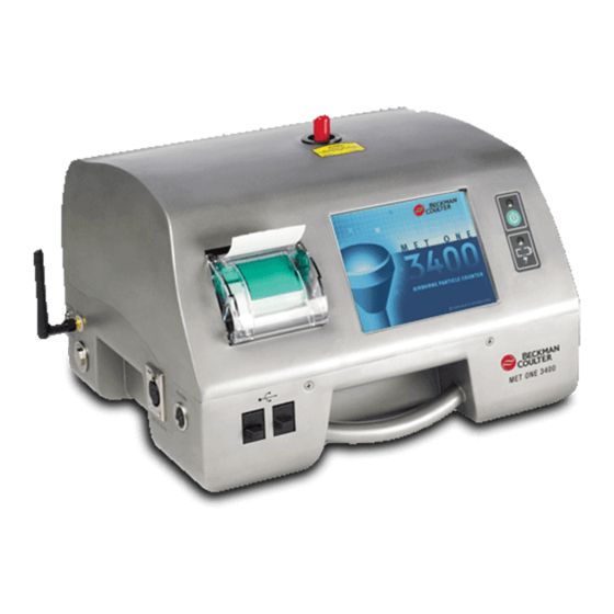
Industry Canada certification and FCC grant. General product information This manual describes the use of the MET ONE 3400 Series Particle Counter. The MET ONE 3400 Series Particle Counter counts and measures the size of airborne particles in cleanroom environments. -
Page 12: Wiring Safety Information
Figure 1 MET ONE 3400 components 1 3400 Series Particle Counter 8 Extension tube for isokinetic probe 2 Rechargeable battery (280-120-2024) 9 Zero count filter 3 AC-to-DC power supply (280-300-5000) 10 RS485 connector assembly 4 Power cord (US) 11 USB Flash drive... -
Page 13: Electrical Connections
• Touch an earth-grounded metal surface such as the chassis of an instrument, a metal conduit or pipe to discharge static electricity from the body. • Avoid excessive movement. Transport static-sensitive components in anti-static containers or packages. • Wear a wrist strap connected by a wire to earth ground. •... -
Page 14: Install The Batteries
Figure 3 Front and side view 1 Sample intake nozzle 8 USB host connector 2 Touchscreen 9 USB client connector 3 Power button 10 Relative humidity and temperature probe connector 4 Battery status indicator 11 Air velocity probe connector 5 Ethernet connector 12 Handle 6 Handle 13 Wireless antenna connector... - Page 15 English 13...
-
Page 16: Assemble The Particle Counter System
Assemble the particle counter system Figure 4 shows the setup of the particle counter system. Figure 4 Particle counter assembly 14 English... -
Page 17: Install The Printer Paper
Install the printer paper To prevent damage to the printer, always operate the particle counter with the recommended thermal paper installed in the printer. If the particle counter must be used without paper, set the print mode to "None". To install a roll of thermal printing paper, refer to Figure Figure 5 Printer paper installation Connect RS485 communication... - Page 18 16 English...
-
Page 19: Network And Communications
Network and communications N O T I C E Only qualified personnel should perform the tasks described in this section. About network and communications setup This section shows the setup for: • Serial communications • Ethernet network communication • Wireless (Wi-Fi) communication •... -
Page 20: Set Wireless Security
• Select the channel (Ad Hoc mode only). • Check Enable Radio if needed. • Select the country. Set wireless security 1. On the Counter Navigation screen, push NETWORK. 2. Select the Wi-Fi Security tab. 3. Configure these options: • Select the security type. •... -
Page 21: Configuration
Table 2 Screen icon descriptions (continued) Icon Function Description Test wizard Test and report wizard for ISO, EU-GMP, FS or BS classification compliance. Refer to Set up the Test and Report Wizard on page 34. Return Return to the previous screen or menu. Configuration About configuration This section describes tasks that are usually done at the initial commissioning stage. -
Page 22: Configure The System
3. Select BASIC MODE. 4. Push RETURN to restart the instrument. Configure the system System settings control how data is measured and stored, user permissions and other system- wide parameters. System settings can be configured as part of instrument commission, or changed later for different applications. -
Page 23: Set The Sample Comments Option
Table 3 Alarm Reasons options Option Description Required After doing a user-initiated sample cycle, the user is required to enter information about all alarms that happen during the cycle. Alarm reasons must be defined in the Alarm Reasons screen. The user cannot exit the Alarm History screen until a reason has been entered for all alarms. -
Page 24: Manage Audible Alarm Settings
Manage audible alarm settings The Sounds tab lets the user select the sound and volume to confirm user interface actions. Sounds that are used for other alarms (stop errors, limit alarms and warnings) are selected in this tab. 1. On the Counter Navigation Screen, push SYSTEM. 2. -
Page 25: Apply An Alarm Reason To A Data Record
3. Push 4. Select a reason from the list. 5. Push REMOVE. 6. Push ENTER to confirm. Apply an alarm reason to a data record Prerequisites: • Alarm reasons must be set to ENABLED or OPTIONAL. Refer to Set the Alarm Reasons option on page 20 for more information. -
Page 26: Manage Backup And Restore Settings
1. On the Counter Navigation screen, push SYSTEM. 2. Select the Units and Alarms tab. 3. Select the HMP RH/T check box to activate or deactivate the HMP probe. Manage backup and restore settings Users with administrator or System Settings permissions can make a backup of configurable settings, and restore the backup settings as needed. -
Page 27: Locations, Areas And Groups
Locations, areas and groups A location defines a space, such as a work bench, that is identified for sample testing. To add, change or remove a location, refer to Location management on page 25. An area is a group of defined locations that are geographically co-located. For example, Cleanroom A is an area. -
Page 28: Copy Settings From Another Location
• Set the sample hold time between count cycles. • Set the sample delay time to allow delay before the sample test begins. 7. Push RETURN to go back to the Add Sample Location screen. Copy settings from another location 1. -
Page 29: Area Management
Area management Add a new area Use up to 15 alphanumeric characters to name an area. 1. On the Counter Navigation screen, push LOCATIONS. 2. On the Area/Location Setup screen, push ADD AREA. 3. Enter the area name and confirm. Note: Use the ALT key to access special characters. -
Page 30: Delete A Group
Delete a group 1. On the Counter Navigation screen, push GROUP. 2. In the Group Settings Management window, select a group. 3. Push DELETE. Add a location to a group 1. On the Counter Navigation screen, push GROUP. 2. In the Group Settings Management window, select a group. 3. -
Page 31: Set The Data Buffer Size
1. On the Counter Navigation screen, push SYSTEM. 2. Select the Custom tab. 3. Select ROTATING BUFFER. Set the data buffer size A change to the buffer size causes all current buffer data to be lost and unrecoverable. 1. On the Counter Navigation screen, push SYSTEM. 2. -
Page 32: Manage Users And Permissions
Manage users and permissions Passwords allow the system administrator to restrict access to the instrument settings. When passwords are enabled, there are two levels of access: • Administrator—Access to all settings on the instrument except for service (factory) access • Operator—Access to review historical data and read current measurement values in the Diagnostics section. -
Page 33: Add A User
Add a user 1. On the Counter Navigation screen, push SYSTEM. 2. Select the Users tab. 3. Push ADD. 4. Select the User Name field and enter a user name. 5. Select the Password field and enter a password. 6. Select the Confirm Password field and enter the same password. 7. -
Page 34: Operation
Option Description Network The user can access, see and change the network settings. User Upload The user can manually trigger the electronic transfer of count records through Ethernet (wired or wireless). 6. Push OK. Operation Log on to the particle counter Prerequisites •... -
Page 35: Use The Filter Scan Probe
Use the filter scan probe N O T I C E The filter scan probe function applies to 1 CFM and 50 LPM units only. 1. On the Counter Navigation screen, push SAMPLE. 2. In the Test screen, push the FILTER icon. 3. -
Page 36: About Reports
particle counters include sample strategies based on common international protocols such as ISO 14644-1, FS 209E, BS 5295 and EU GMP Annex 1. The wizard steps through seven data entry points: • Selection of the type of standard or regulatory guideline: EU GMP, ISO 14644-1, FS209E, BS5295 or Averages (user-defined test protocols) •... -
Page 37: Use Existing Data
Use existing data The Test and Report Wizard can include existing date for the selected standard and location. 1. Select the Use Existing Data checkbox. 2. Enter the date range for the existing data. 3. Push BEGIN SAMPLING. Report test results •... - Page 38 Figure 6 Averages report Figure 7 Buffer report (all buffer records) 36 English...
-
Page 39: Set Automatic Print Functions
Set automatic print functions Note: If the sample period is very brief and the hold time is zero, some sample data may be skipped. 1. On the Counter Navigation screen, push PRINTER. 2. On the Print Center screen, select the Sample Print Mode field. Select an option for automatic printing. -
Page 40: About Status Values In Exported Data
3. Select PDF, Comma Separated File, Tab Separated File, XML or PortAll. Note: The PDF option shows only after the PDF option has been set to on. Refer to Turn on the PDF option on page 29. 4. If PDF was selected and the settings on the PDF tab under System Settings should be used, select the box to enable PDF Page and File Break Rules. -
Page 41: Configure And Enable The Ftp Function
Configure and enable the FTP function With firmware V4.08, the particle counter can be configured to transmit data via Ethernet (wired or wireless when the wireless option is installed) to an FTP server. This particle counter can connect to servers that use FTP or FTPS (Explicit TLS/SSL). 1. -
Page 42: Maintenance
Maintenance W A R N I N G Multiple hazards. Do not disassemble the instrument for maintenance or service. If the internal components must be cleaned or repaired, contact the manufacturer. C A U T I O N Personal injury hazard. Only qualified personnel should conduct the tasks described in this section of the manual. Clean the instrument exterior The instrument exterior can be cleaned as needed. -
Page 43: Battery Recharge Intervals
Prerequisite: Install the batteries in the instrument. Refer to Install the batteries on page 12. N O T I C E Discard the used batteries according to local regulations or contact the manufacturer. Do not put exhausted batteries in the domestic waste. 1. -
Page 44: Factory Settings
Table 7 System Diagnostics screen example - Clock battery failure (continued) Signal Value Status Battery 2 (top) 16.44 VDC PASS Laser current – – For troubleshooting that involves technical support from the manufacturer, the user may need to fax a system status printout to technical support. 1. -
Page 45: Parts For The 100 Lpm Counter (3445)
Parts for the 50 LPM counter (3423 and 3425) (continued) Description Quantity Item number Filter, Zero Count for 50 LPM 2087939-01 ® Tubing, Hytrel , 0.953 cm (0.375 in.) ID, 1.27 cm (0.5 in) OD 10 ft 960380 Parts for the 100 LPM counter (3445) Description Quantity Item number... -
Page 46: Spare Parts Kit (2087919-01)
3400 series parts (continued) Description Quantity Item number High pressure diffuser, 50 L/min (1.77 CFM), 3/8-in. barb 2080732-12 High pressure diffuser, 28.3 L/min (1.0 CFM), 3/8-in. barb 2080732-13 USB 2.0 high speed, 1 m (3.3 ft) cable 460-400-4798 USB to RS-232 adapter, DB-9 null modem 2088012-02 USB to RS-485 adapter 2088012-01... - Page 48 Tel. +49 (0) 2 11 52 88-320 SWITZERLAND Fax (970) 669-2932 Fax +49 (0) 2 11 52 88-210 Tel. +41 22 594 6400 orders@hach.com info@hach-lange.de Fax +41 22 594 6499 www.hach.com www.hach-lange.de © Hach Company/Hach Lange GmbH, 2011-2013. All rights reserved.
Need help?
Do you have a question about the MET ONE 3400 and is the answer not in the manual?
Questions and answers